I decided that lighting up some pumpkins would be nice during Halloween and and I didn't want to plug anything in or buy something complicated. Looked into photo diodes a bit to understand how they work and was able to make a really simple amplifier circuit to turn on some white LEDs I had laying around.
Photo Diodes:
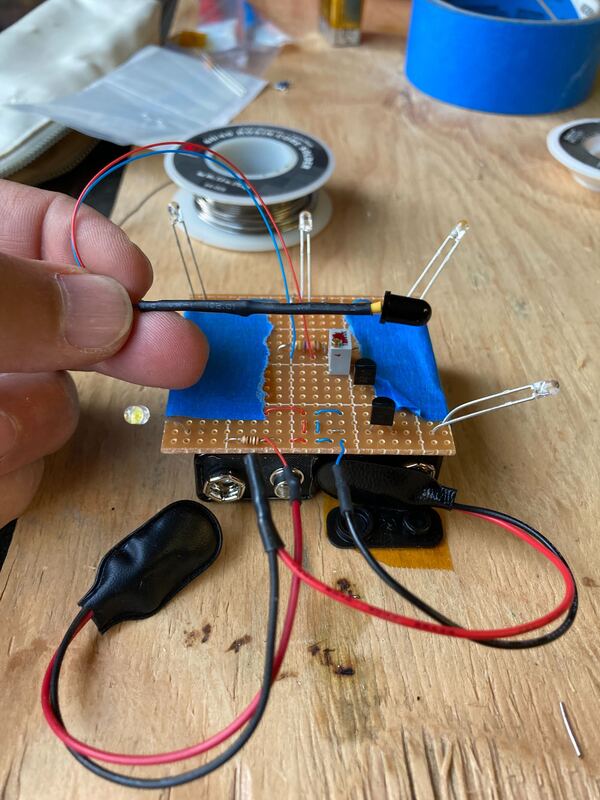
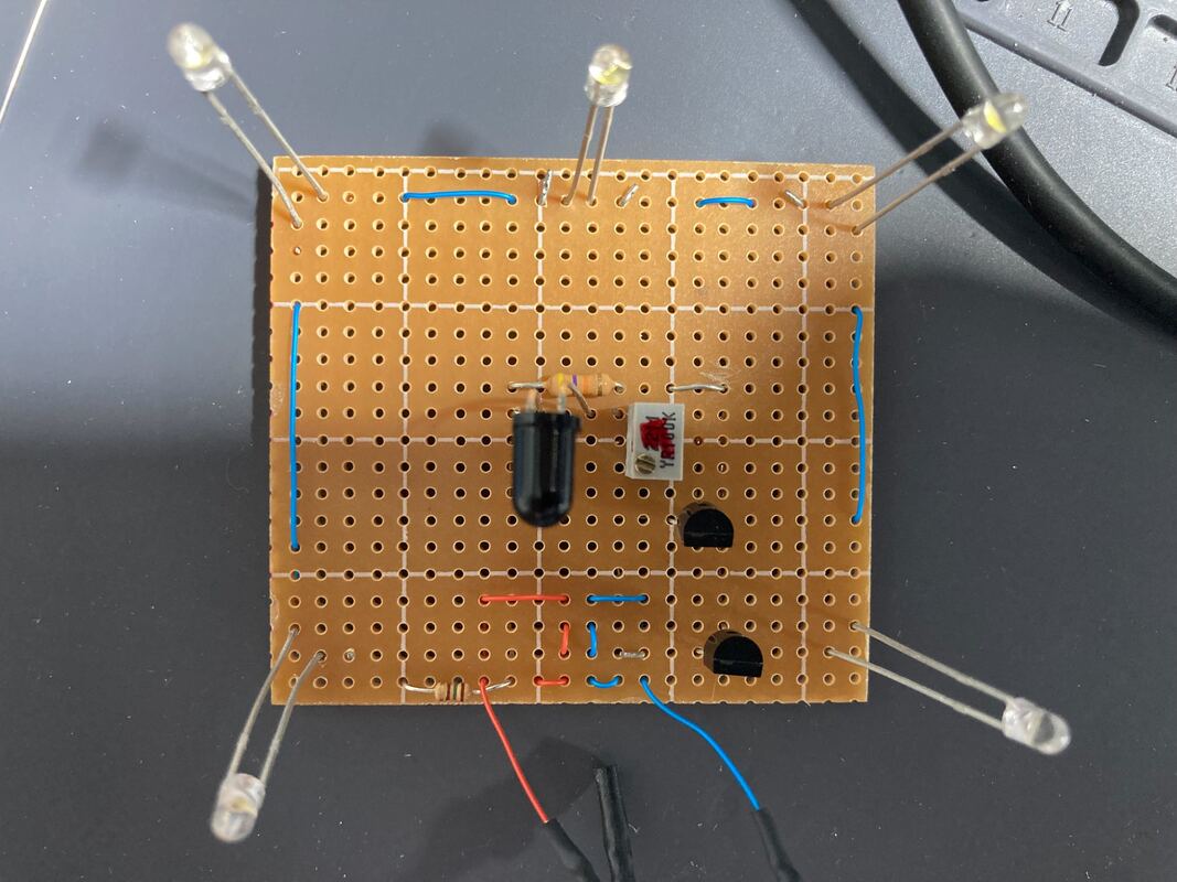
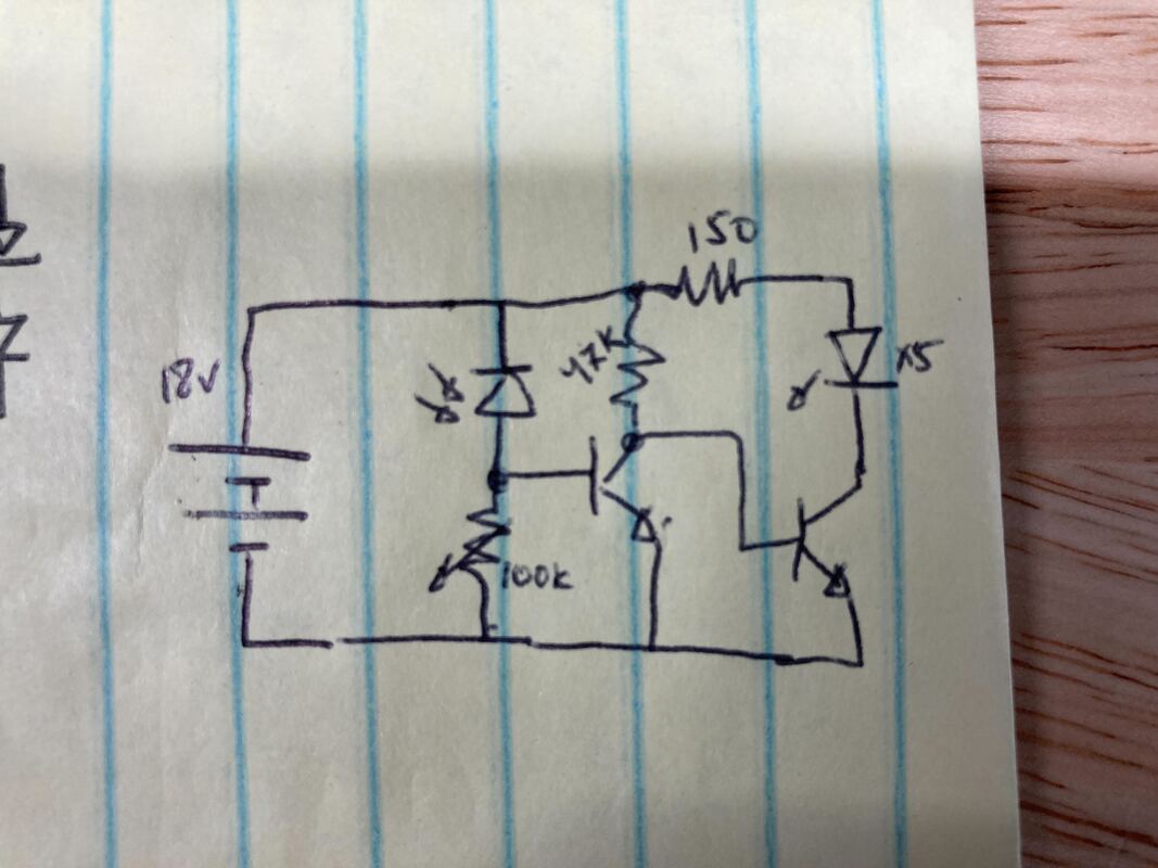
These can be thought of as and used as just normal diodes which merely become leakier if you shine light on them. This means you generally use them in a reverse biased configuration in a circuit (if you look up the physics, the more reverse biased, the more sensitive it becomes). So you have it reverse biased with its cathode at a higher voltage than its anode. In the dark it has some very tiny reverse leakage (in photodiodes it's called dark current), the part I chose as in the nano Amps. Then you shine a light on it, and those nano Amps go allllll the way to 10's of micro Amps (yeah, surprising). So if you look at the circuit doodle in the picture, the 100k pot keeps the base of that BJT at 0v until the photodiode "leaks" enough current across the 100k to raise the base voltage above 0.6v which then turns on that bjt which turns off the one controlling the actual LEDs. I ended up using an extra 200k from the pot to ground because even with just the 100k pot turned all the way to 100k it was too sensitive (so with a lower resistance, a higher current is needed to get that 0.6v which means the LEDs come on even if the sensor is just in a faint shadow). Adding the 200k made the whole thing 300k to ground, which means now 0.6v / 300k = 2uA of light current will turn the LEDs on. I probably should have gotten a 500k pot or something but ehh, the project was conceived and built in one week. Looks great, draws 15-20mA, which should last us 3 or 4 days on the 9v battery's 300-500mAh capacity. Happy Halloween!
Photo Diodes:
These can be thought of as and used as just normal diodes which merely become leakier if you shine light on them. This means you generally use them in a reverse biased configuration in a circuit (if you look up the physics, the more reverse biased, the more sensitive it becomes). So you have it reverse biased with its cathode at a higher voltage than its anode. In the dark it has some very tiny reverse leakage (in photodiodes it's called dark current), the part I chose as in the nano Amps. Then you shine a light on it, and those nano Amps go allllll the way to 10's of micro Amps (yeah, surprising). So if you look at the circuit doodle in the picture, the 100k pot keeps the base of that BJT at 0v until the photodiode "leaks" enough current across the 100k to raise the base voltage above 0.6v which then turns on that bjt which turns off the one controlling the actual LEDs. I ended up using an extra 200k from the pot to ground because even with just the 100k pot turned all the way to 100k it was too sensitive (so with a lower resistance, a higher current is needed to get that 0.6v which means the LEDs come on even if the sensor is just in a faint shadow). Adding the 200k made the whole thing 300k to ground, which means now 0.6v / 300k = 2uA of light current will turn the LEDs on. I probably should have gotten a 500k pot or something but ehh, the project was conceived and built in one week. Looks great, draws 15-20mA, which should last us 3 or 4 days on the 9v battery's 300-500mAh capacity. Happy Halloween!