Last year my friend gave me a super old drone his uncle had and I finally took off the motor from it and tried my hand at making a motor controller. I know there are basically 2 levels of BLDC control: Trapezoidal and FOC. The ESC that was already on the drone was trapezoidal and that's easier any way so I'll be doing that. FOC (Field Oriented Control) is more complex so I'll leave that for later.
Theory
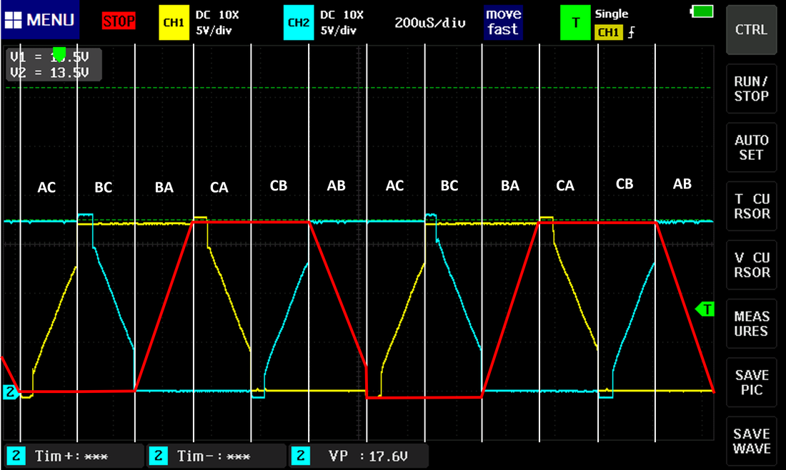
I started with measuring what the phase wires of the stock ESC do. Internet says they run by feeding in power and a PWM signal that says how much throttle to do. The throttle level, in turn, chops up the trapezoidal drive's output so the motor sees and average (or is it RMS?) of some lower voltage, which makes it spin slower. As far as I can tell, in BLDC's (Brushless Direct Current Motors) voltage dictates speed and current dictates torque.
So the stock ESC seems to have a max speed such that each commutation cycle is about 200us. It increases from that a bit as you left off the throttle, then at some point turns to chopped up PWM instead of a clean signal. It also has no feedback from the motor so this is a "sensorless" design where the ESC infers the motor's position based on the leg that is not being driven at any given commutation cycle. The voltage on this leg is induced by the EMF it feels from the permanent magnets on the rotor. The ultimate goal is to change commutation 30 electrical degrees after the back EMF on this leg crosses the half way point of the drive voltage. This means the current in the coil changed direction (zero crossing) which means the coil was directly aligned with a magnet, 30 electrical degrees after that puts that magnet in the middle of the two coils which is the optimal point to "pull" the rotor round to the next commutation cycle. If we commutate right at the zero crossing it'll still work but just not optimally. I'm going for that for now...
Theory
I started with measuring what the phase wires of the stock ESC do. Internet says they run by feeding in power and a PWM signal that says how much throttle to do. The throttle level, in turn, chops up the trapezoidal drive's output so the motor sees and average (or is it RMS?) of some lower voltage, which makes it spin slower. As far as I can tell, in BLDC's (Brushless Direct Current Motors) voltage dictates speed and current dictates torque.
So the stock ESC seems to have a max speed such that each commutation cycle is about 200us. It increases from that a bit as you left off the throttle, then at some point turns to chopped up PWM instead of a clean signal. It also has no feedback from the motor so this is a "sensorless" design where the ESC infers the motor's position based on the leg that is not being driven at any given commutation cycle. The voltage on this leg is induced by the EMF it feels from the permanent magnets on the rotor. The ultimate goal is to change commutation 30 electrical degrees after the back EMF on this leg crosses the half way point of the drive voltage. This means the current in the coil changed direction (zero crossing) which means the coil was directly aligned with a magnet, 30 electrical degrees after that puts that magnet in the middle of the two coils which is the optimal point to "pull" the rotor round to the next commutation cycle. If we commutate right at the zero crossing it'll still work but just not optimally. I'm going for that for now...
Implementation
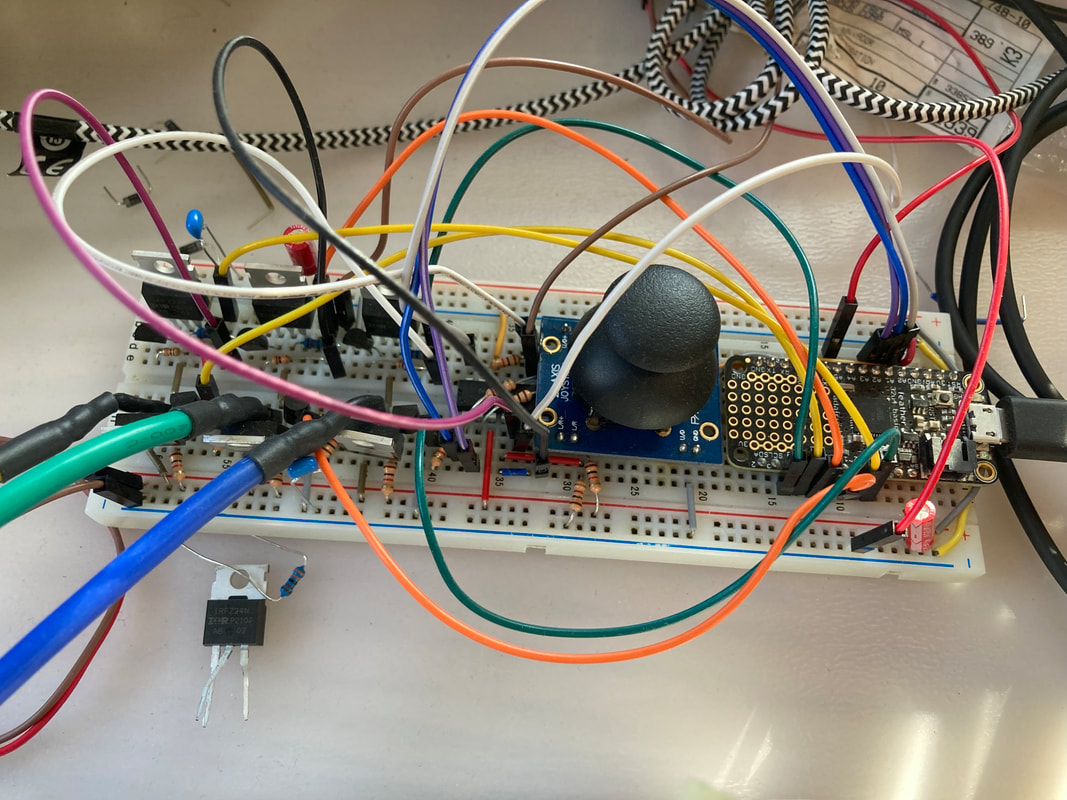
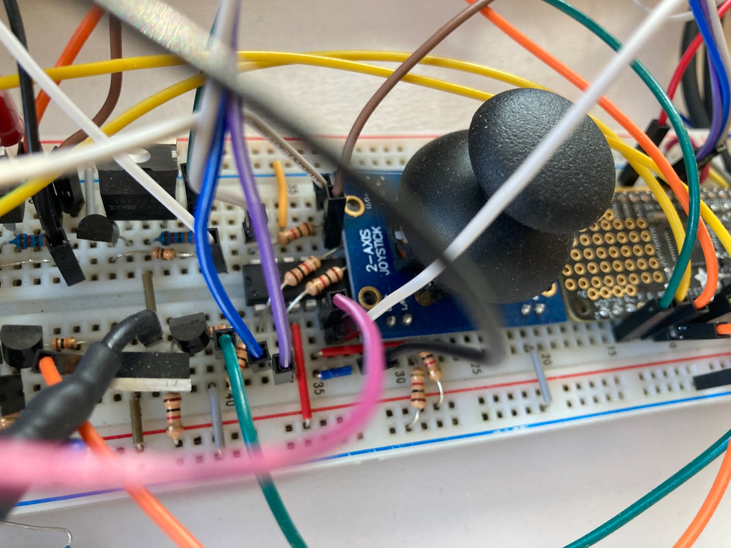
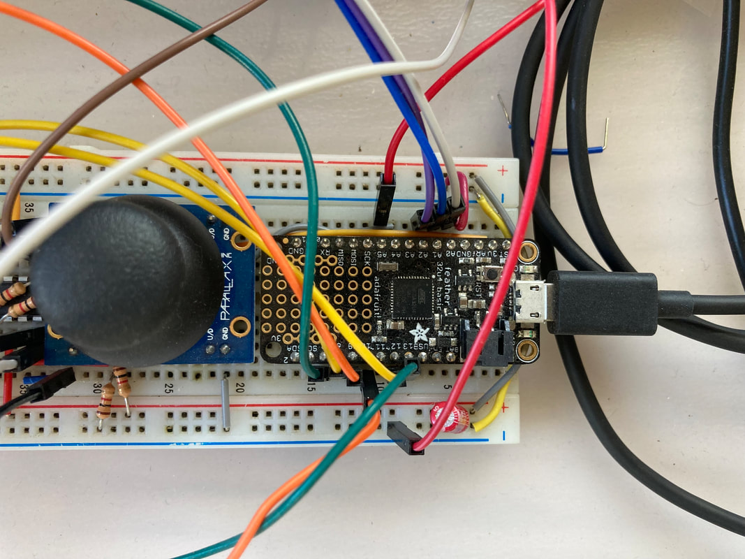
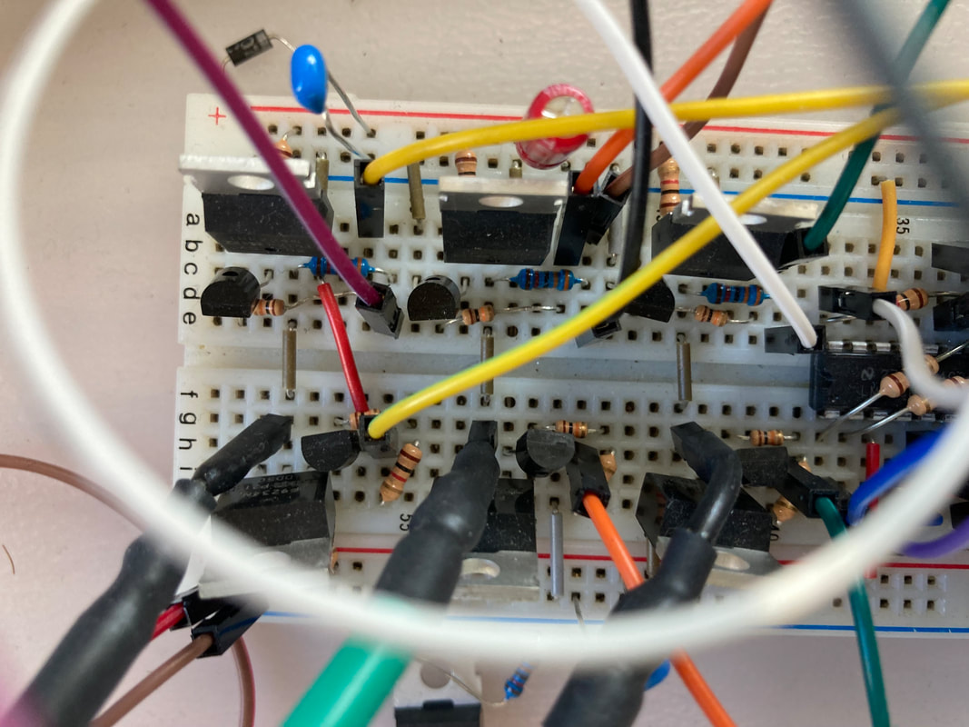
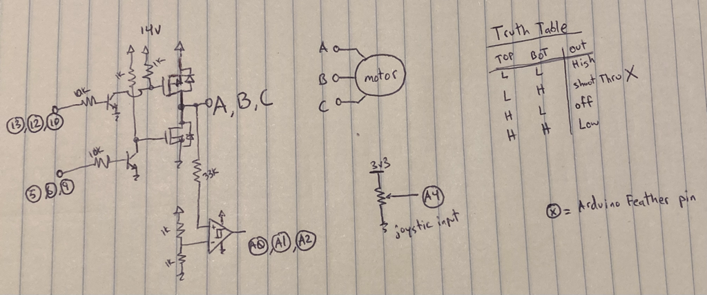
So that's a really crappy look at theory, how do you actually implement it? Well you drive the coil through 2 FETs, one pulls it high to power (in our case ~14v, to line up with a 4s lipo battery pack), and the other pulls it to ground. This push/pull FET config is known as a half bridge. You put 3 of these on a design where each of the half-bridges drains are connected to each of the Motor's legs and you have an "inverter". This is the heart of the ESC...or maybe it's the muscle, not sure. Each of the 6 FETs is driven by a bjt that pulls the gate to ground in an open collector fashion. This means the gates of both the P-FET (high) and N-FET (low) is pulled passively to 14v (another reason why I chose 14v is that it's a safe amount for normal FETs to have their gates pulled to, otherwise we'd have to get fancy with drivers). These pullup resistors get pulled to ground via bjt's that are driven, through resistors, by a microcontroller (in our case, the Adafruit Feather which is like a tiny arduino). So by carefully pulling the motor leg A high and motor leg B low (and not driving motor leg C), we can align coil AB in a certain direction. Then we commutate and leave motor leg A high but pull motor leg C low while not driving motor leg B, this advances the motor one more commutation and we get movement! Most people will use motor driver IC instead of commanding individual FETs and bjt's but I figured I enjoy learning the low level stuff. Plus, I was able to see something called "the miller effect" in action when I accidentally had too high of value resistors on the pullups of the FET gates. When I had 10k on the gate FETs I was seeing that the drain was not able to quickly change from low to high or high to low. There is an imaginary capacitor going from the the FET gate to the drain and if the gate drive resistor is too high then that cap cannot get filled fast enough to honor the command that the gate is receiving. Gotta love these tiny lessons! So I wired each of those bjt bases to the arduino's PWM capable output pins.
Now it's one thing to be able to drive the motor at a given timing that's preset but we need to sense the zero crossing of the undriven coil so that we can know when to switch the commutation. This is called "closed loop" control whereas if we just commutate based on a set length of time then that's "open loop" control. We can sense when the voltage of each leg crosses the 7v mark (power voltage div 2) with a comparator and feeding its output to the Arduino too. Now we know if each motor leg's voltage is above or below the midpoint voltage.
Add a joystick to the mix (which is really just a potentiometer) and we have a full way of controlling the speed of the motor. We read the joystick's position, turn that into a throttle value, and change the timing of our PWM chopping such that more or less of the full 14v is getting to each coil on average. This PWMing makes everything more complicated though since now we need to know when we are on the driven portion of the PWM vs the undriven portion because that's when we need to look for the v/2 comparator output. I implemented this in the code via interrupts. It's super clunky.
Conclusion
The output of the project is that it works! I was able to start the motor via driving it open loop at a low throttle for a bit until we have enough back EMF to sense off of for a closed loop config. I can move the joystick and get more or less speed on the motor too which feels great. No prop on this right now since I'm at my table but commutation was really my goal and that's been achieved.
The output of the project is that it works! I was able to start the motor via driving it open loop at a low throttle for a bit until we have enough back EMF to sense off of for a closed loop config. I can move the joystick and get more or less speed on the motor too which feels great. No prop on this right now since I'm at my table but commutation was really my goal and that's been achieved.
Next steps:
- I'm commutating very poorly, this method of generating interrupts when the comparator output changes pin states is kinda silly. I doubt any big boy ESC's do that.
- I feel like the whole open loop to closed loop change over can be much better. Same goes from PWM to direct drive at high speeds.
- I'm spending way too much processor cycles on interrupts and other bs. I have no bandwidth left to even calculate my own RPM or commutation time or anything. This is no good.
- I wonder if the whole discrete inverter design is too limiting for me right now. Maybe a driver that I can just feed tiny discrete signals to would be best. Right now I'm just relying on the code to not generate shoot through's... that's no good.
| crapazoidal_commutation.ino |
