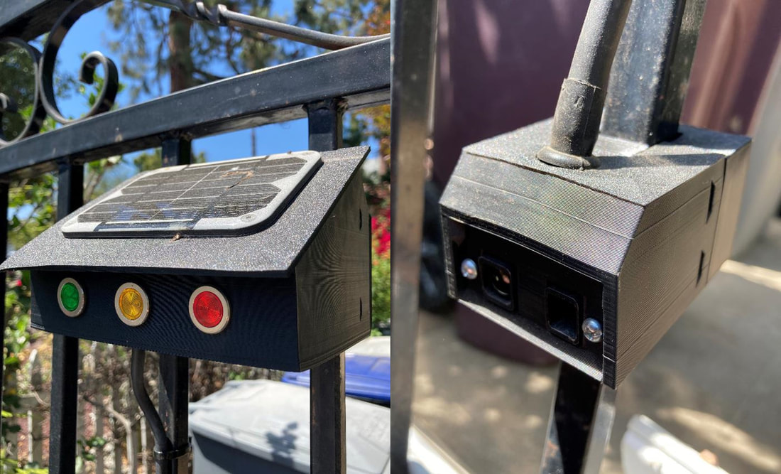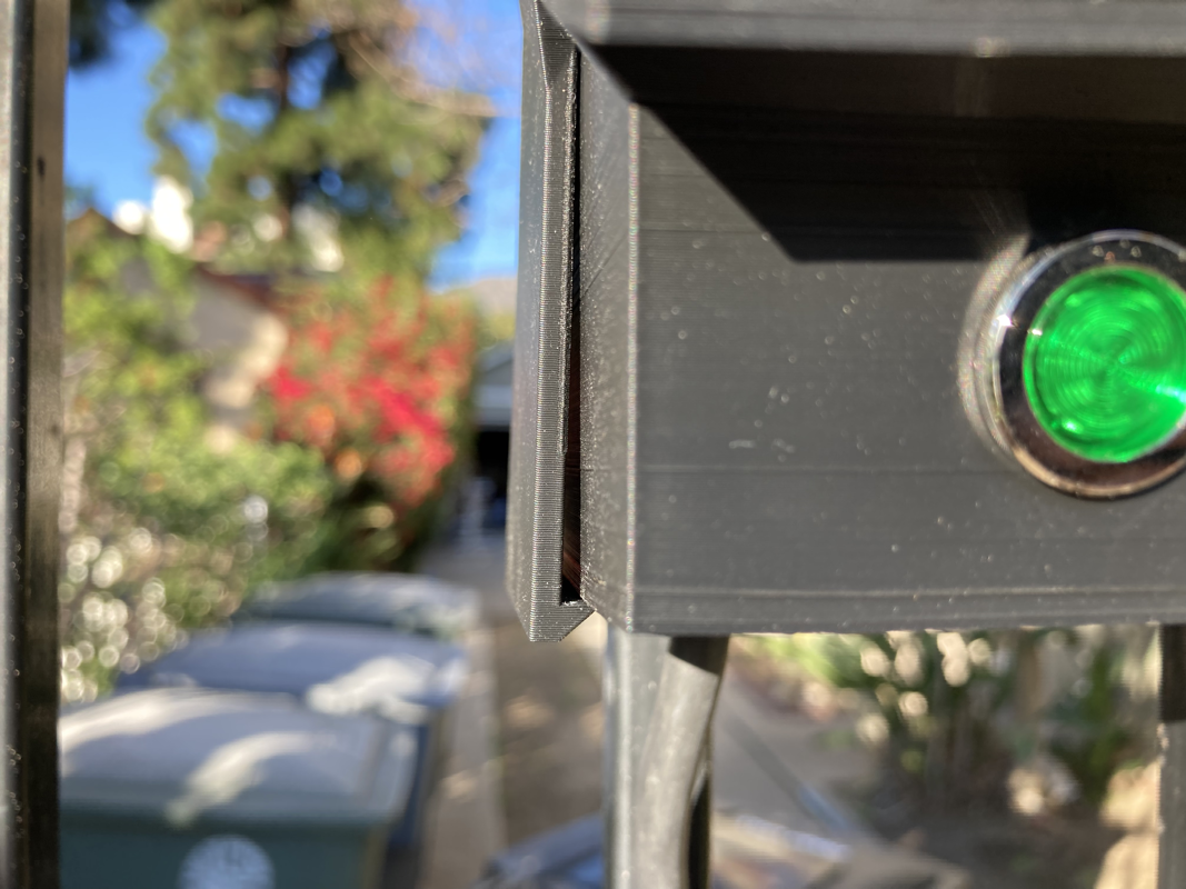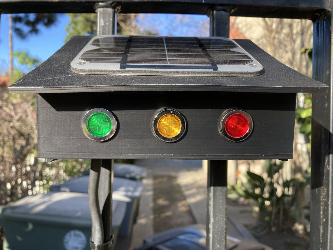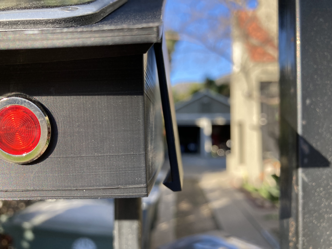
IP Testing home addition. My guess is this is IP44: pretty tight against dust and debris, so-so against water but good enough for heavy rain
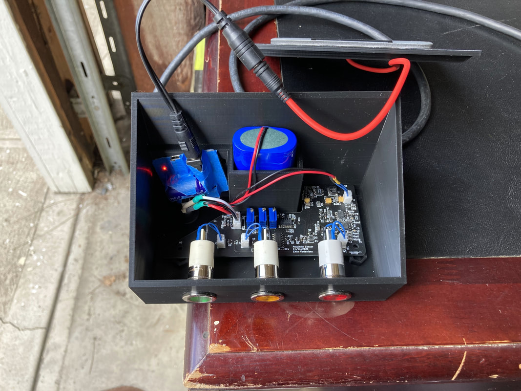
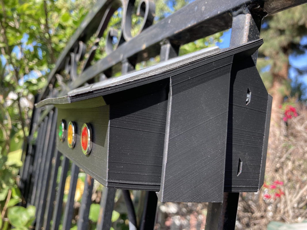
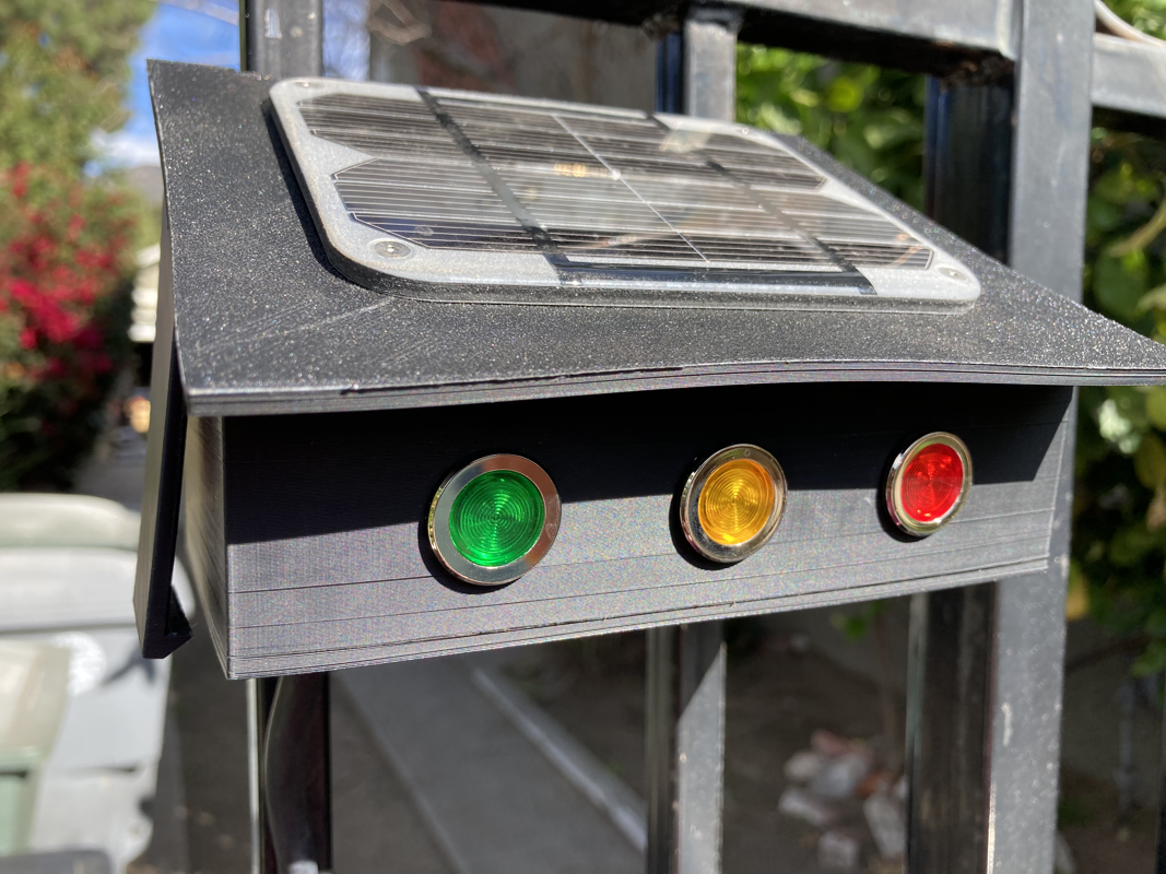
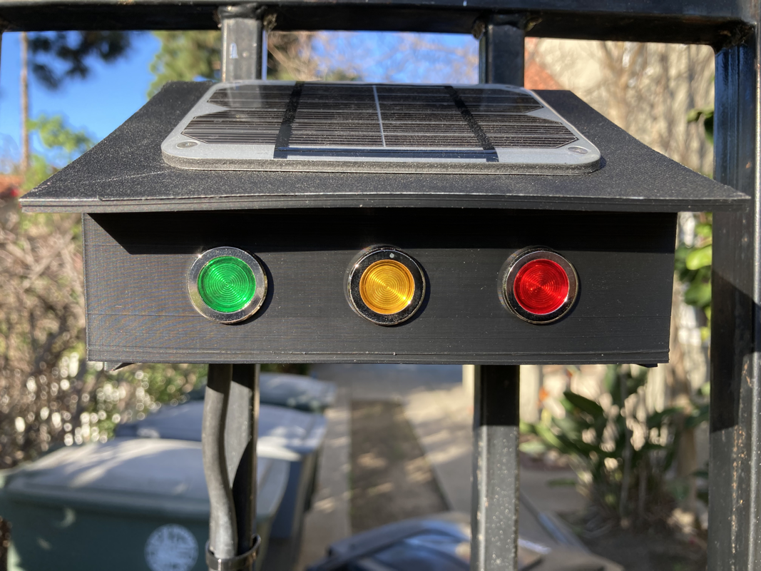
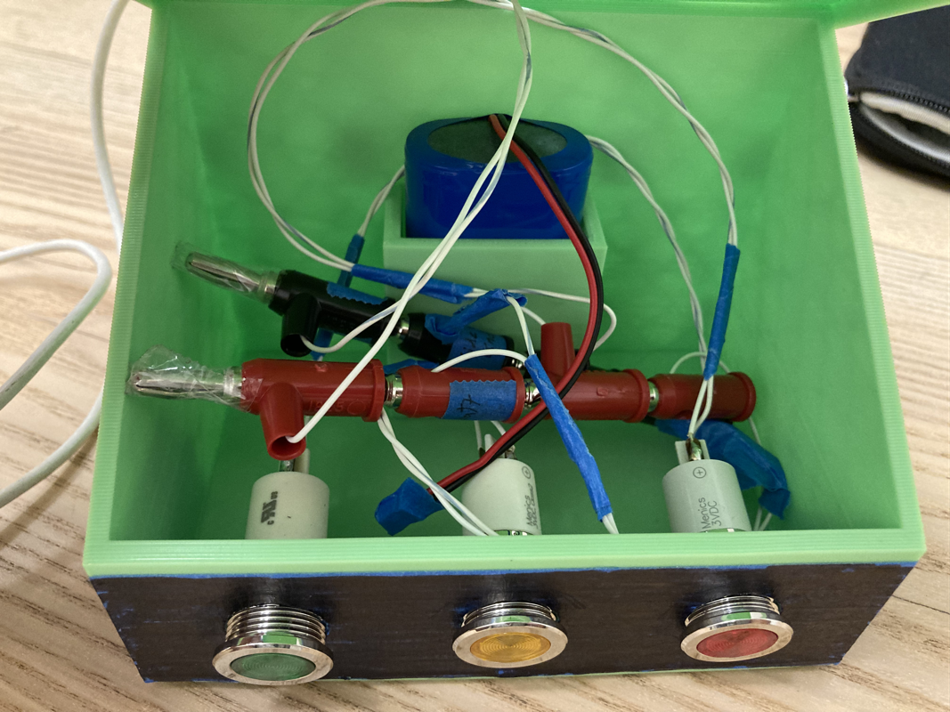
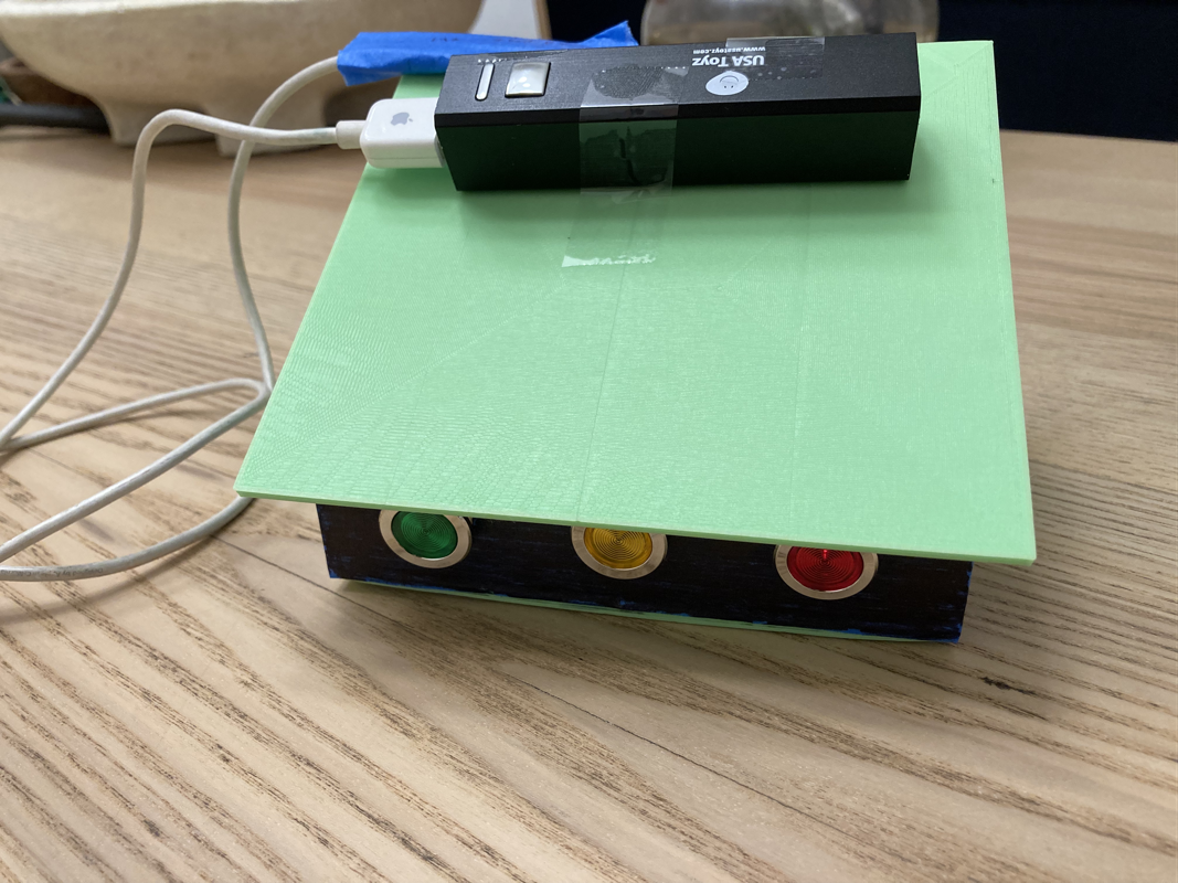
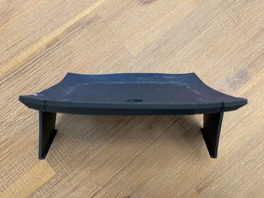
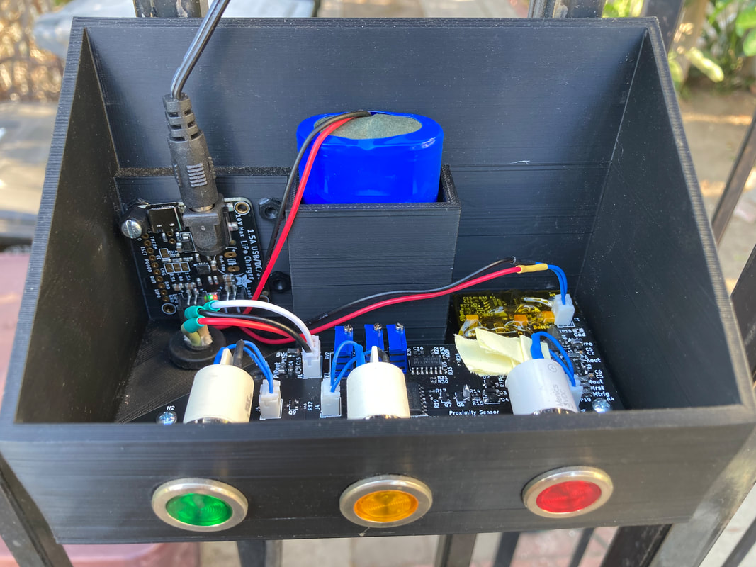
Box done
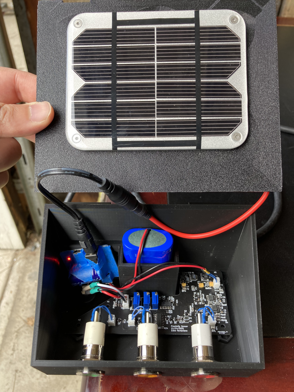
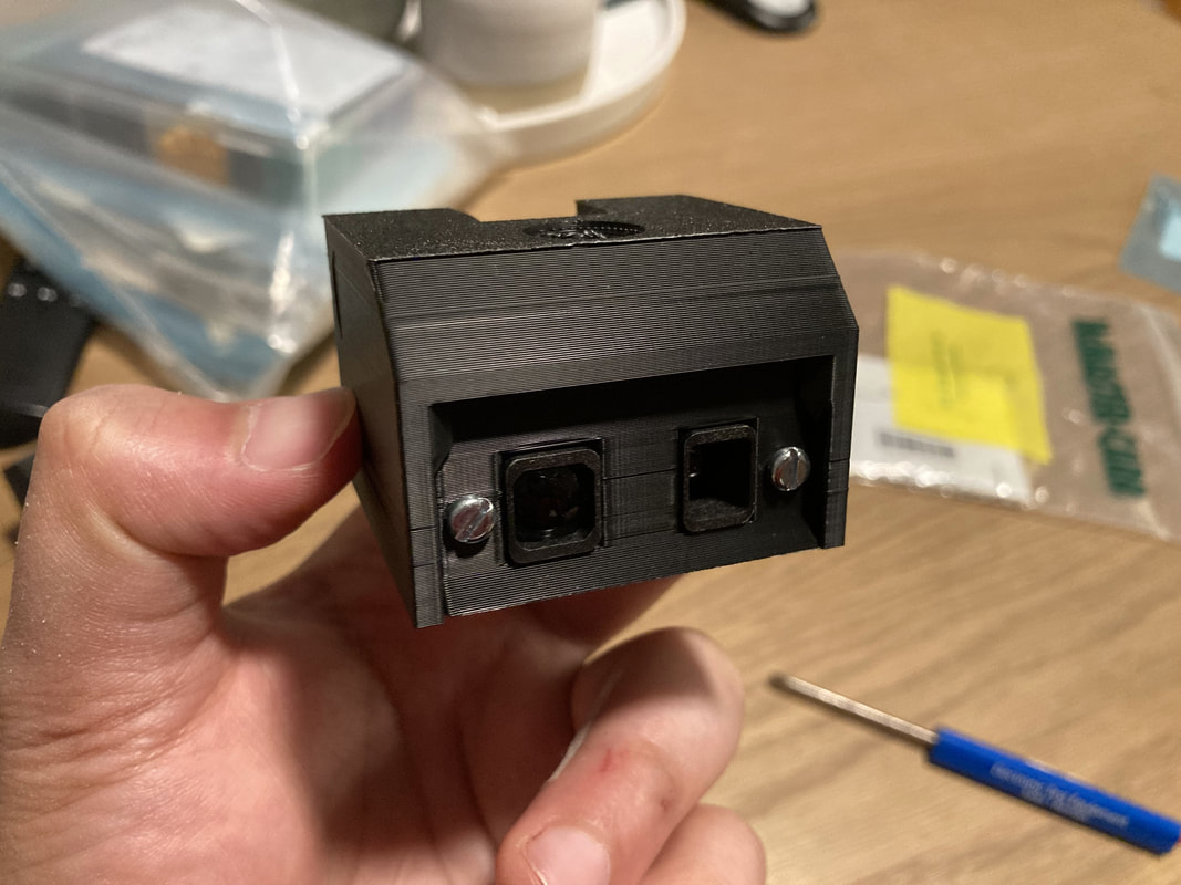
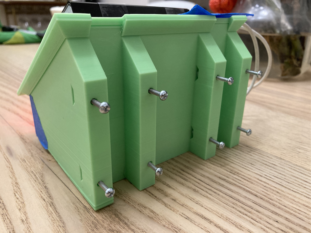
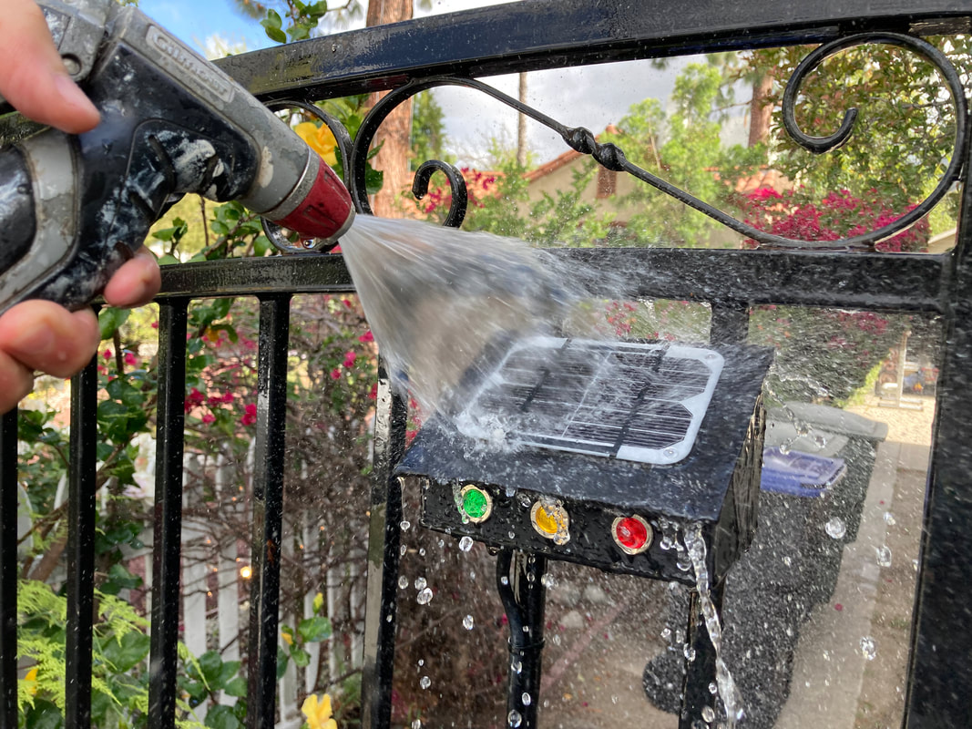
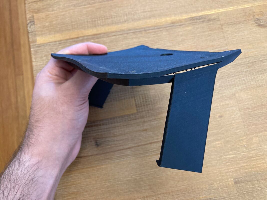
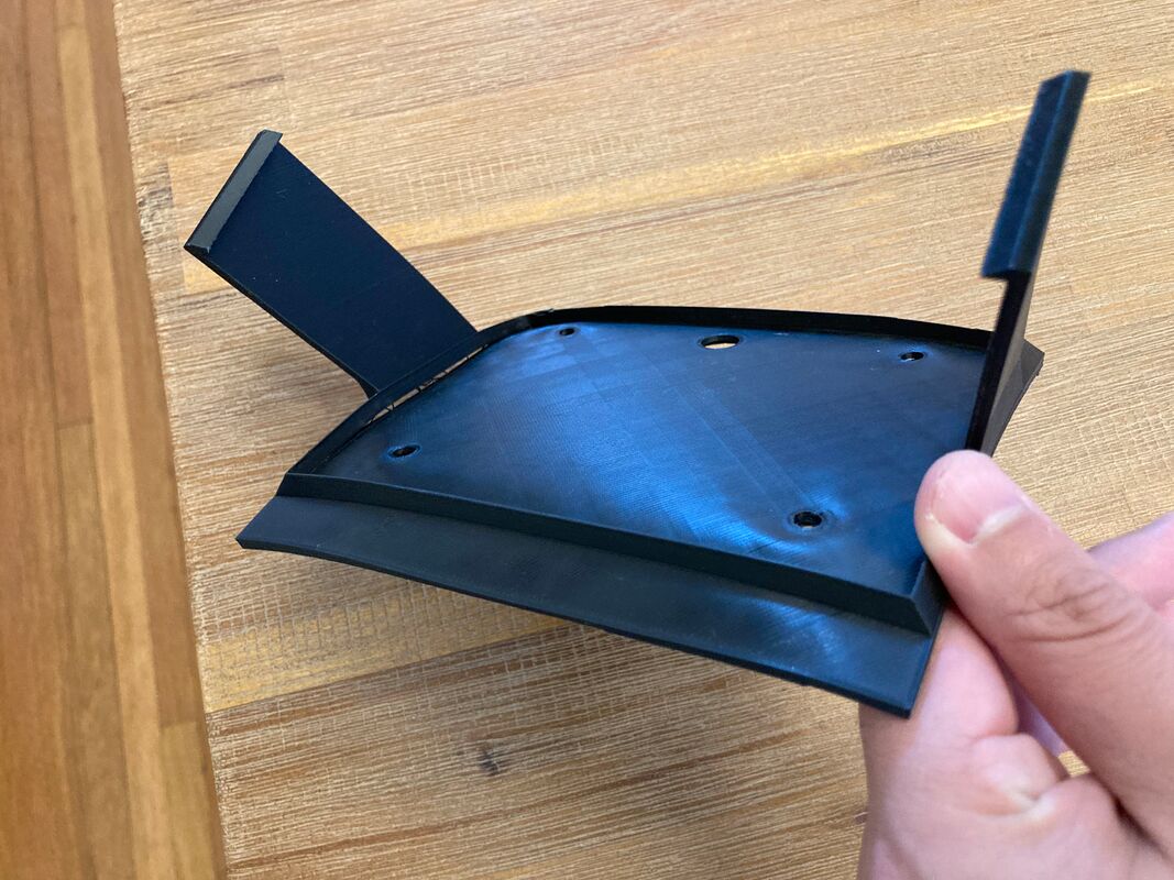
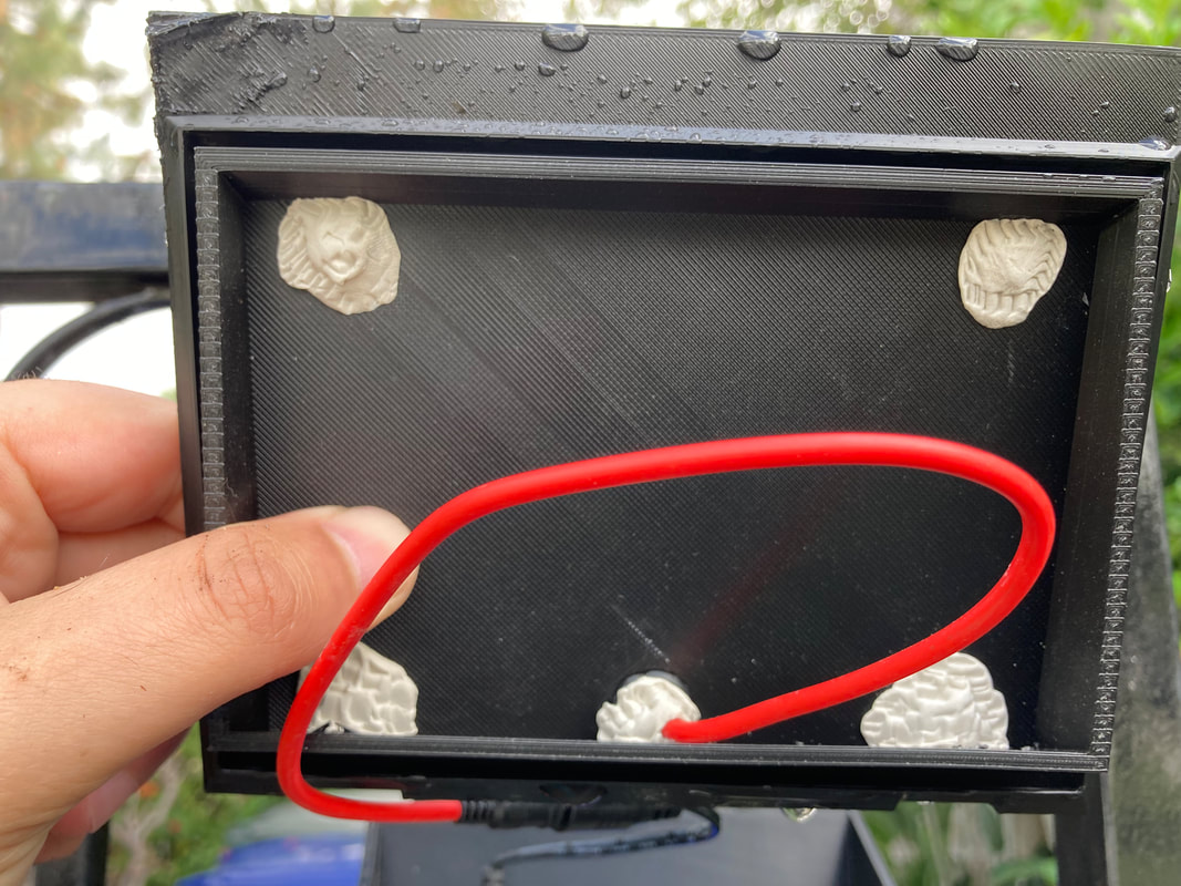
After the box's top warping from the heat a few times I got curious as to why the top was warping and the box was staying normal. I have a sneaking suspicion that it was the solar panel that was growing and shrinking with the weather and since the mounting holes were so tight (to make it water tight) the top warped to accommodate the tiny expansion and shrinkage of the panel. To get around this I just over drilled the holes to allow for a bit of play in the mounting holes, then held it with nuts and put putty on the under side to completely cover the holes (along with the opening for the panel wire. Then a quick water ingress test with the hose proved we had no leaks. Good enough for now, until the putty dries up or something, but I think it'll hold for a long while. Just to be sure about CTE though I did redesign the top to have a groove for the base's walls to sit in. This way, the top hugs the walls on both the inside and outside to keep stuff from getting in.
After the box's top warping from the heat a few times I got curious as to why the top was warping and the box was staying normal. I have a sneaking suspicion that it was the solar panel that was growing and shrinking with the weather and since the mounting holes were so tight (to make it water tight) the top warped to accommodate the tiny expansion and shrinkage of the panel. To get around this I just over drilled the holes to allow for a bit of play in the mounting holes, then held it with nuts and put putty on the under side to completely cover the holes (along with the opening for the panel wire. Then a quick water ingress test with the hose proved we had no leaks. Good enough for now, until the putty dries up or something, but I think it'll hold for a long while. Just to be sure about CTE though I did redesign the top to have a groove for the base's walls to sit in. This way, the top hugs the walls on both the inside and outside to keep stuff from getting in.
Latch fix and new charger
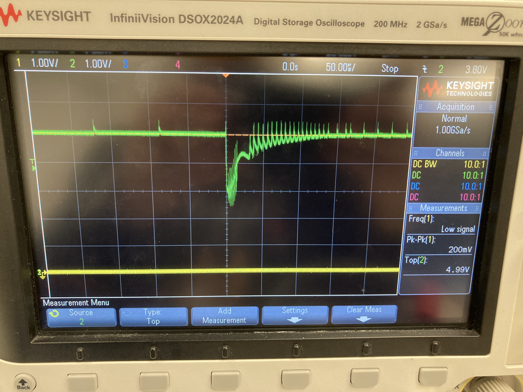
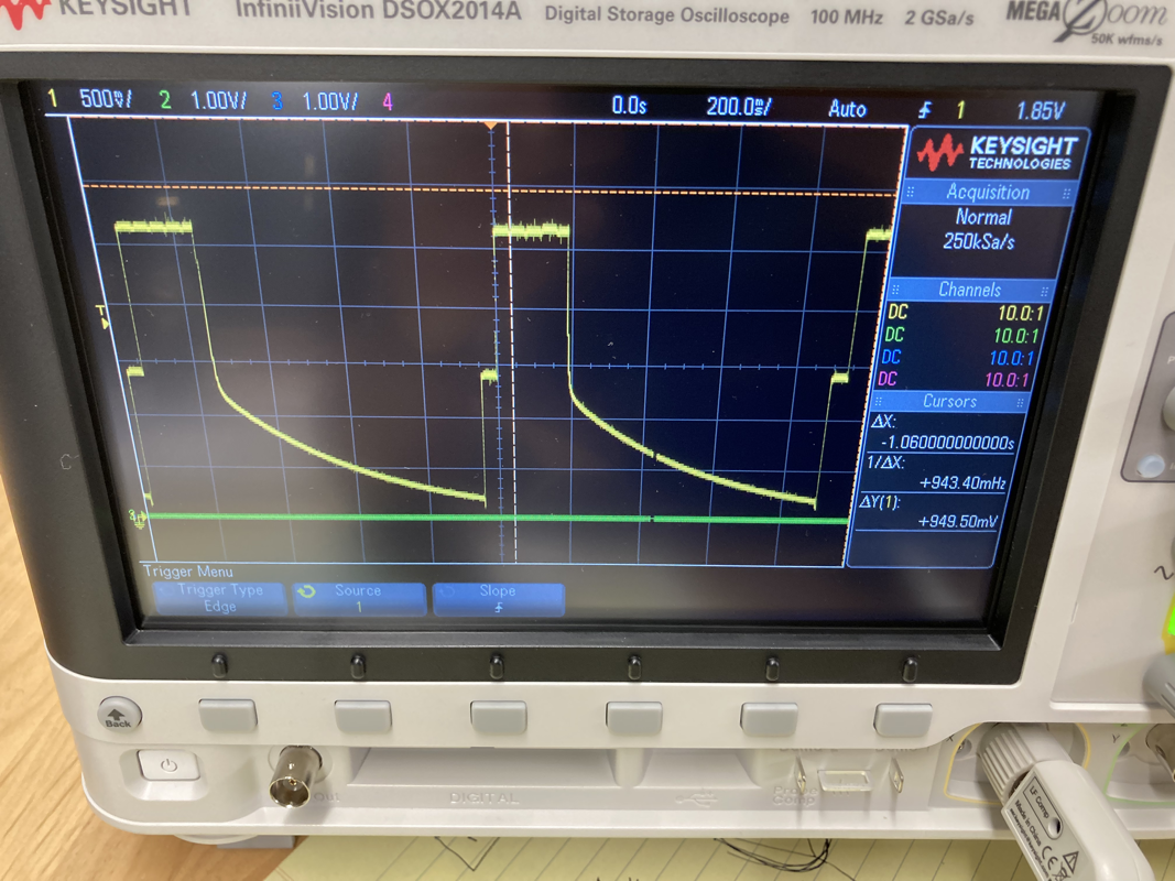
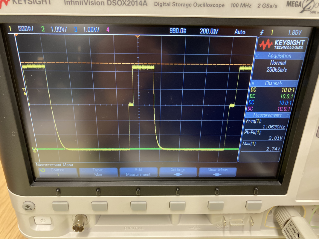
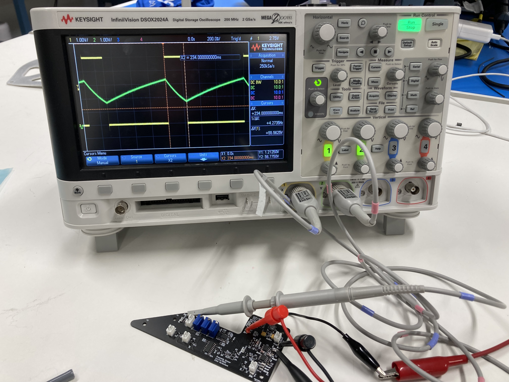
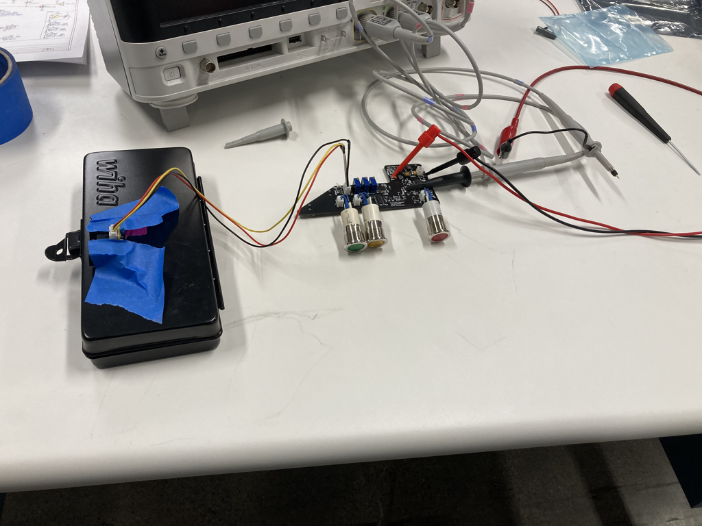
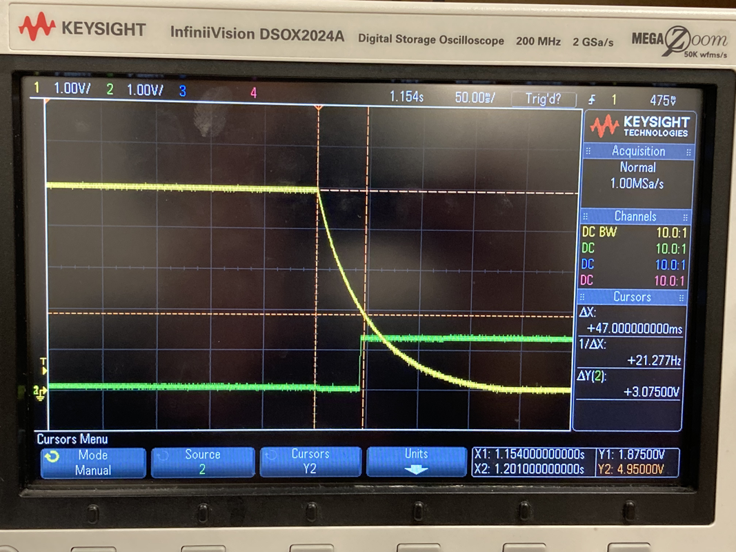
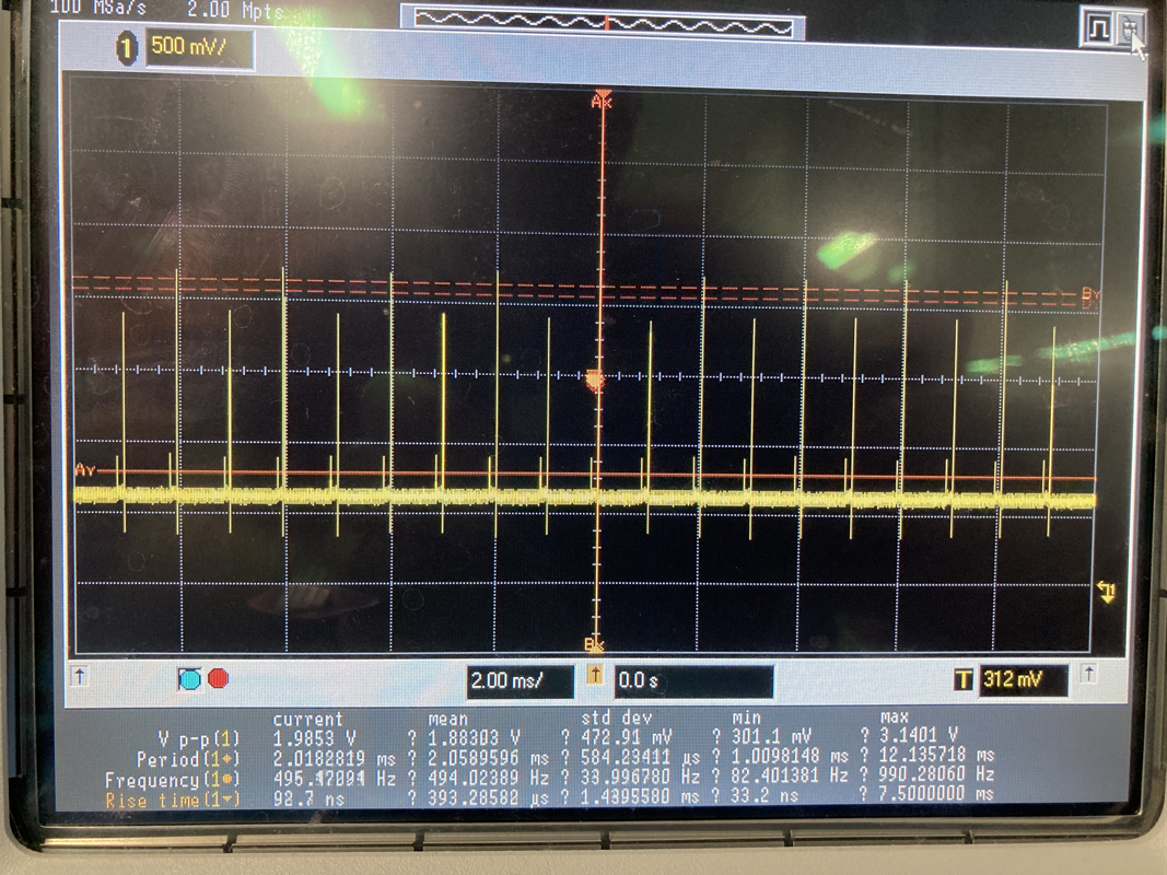
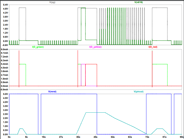
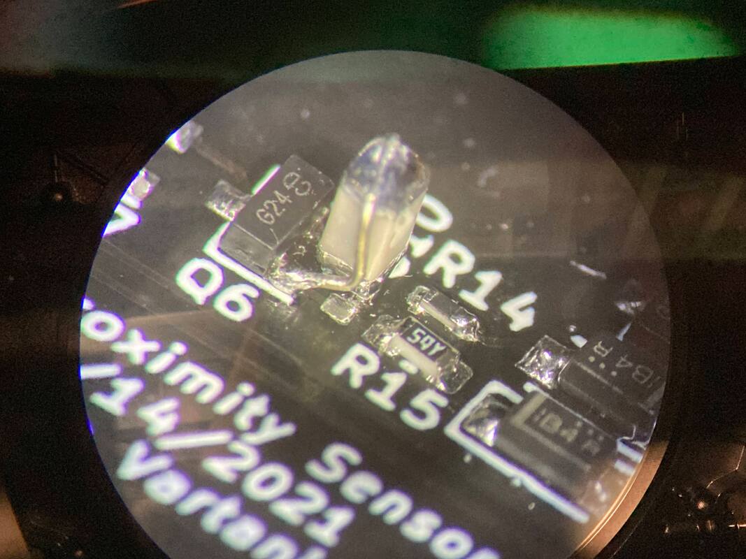
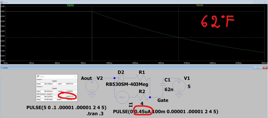
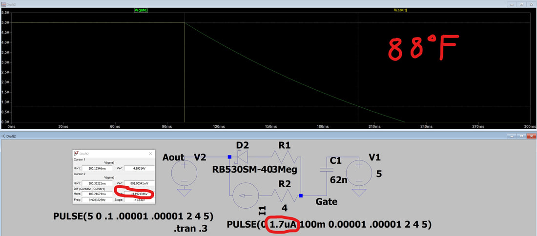
Boy had a hard time with this but I learned some great stuff, but i'll have to summarize since the journey is too boring for a blog. So I kept noticing that sometimes, when it was hot out and my car was in the driveway that the red light would blink for 10s, turn off, then start again for another 10s. It was clear that the SR latch was not latching or was becoming unlatched. After a ton of probing with the oscope I settled on the logic AND section that passes the Pgreen signal and the 47ms delayed signal of the Astable timer (since the sensor's output is unreliable for the first 35ms or so). I was seeing a way different discharge curve for the 47nF/3Mohm circuit when it was hot vs cold. At first I thought it was the cap's temp co since I had just used any old cap for this timing. But when I replaced it with a bigger 62nF class 1 cap (C0G material dielectric that does not shift with temperature at all, keeping the capacitance stable) the discharge curve behavior didn't change at all. So it was either that the gate of the FET was actually sinking current or the back-biased diode was leaking current. Looked into the diodes I used and sure enough at 5v back bias the diode already had 2uA of leakage at room temp. When you calculate the peak current as the cap discharges from 5v across a 3Mohm resistor you get 1.3uA, which means the back biased diode leak is on par with the forward biased diode path, making the RC discharge faster than intended and turning on the logic AND before the 30ms delay. Worse yet, as the diode gets hot it's leakage increases (20uA at 75C). I even did a SPICE model of the circuit to loosely simulate how much leakage we're talking about when I matched the curves up at hot and cold, and sure enough the leakage in my model looks about what the leaky diode's datasheet said. Looked around and replaced the diode with a much lower leakage diode (still looked for Schottky but picked a way lower rating, not much above the current/voltage I'm actually using which means the leakage is lower due to the device just being smaller in general).
Boy had a hard time with this but I learned some great stuff, but i'll have to summarize since the journey is too boring for a blog. So I kept noticing that sometimes, when it was hot out and my car was in the driveway that the red light would blink for 10s, turn off, then start again for another 10s. It was clear that the SR latch was not latching or was becoming unlatched. After a ton of probing with the oscope I settled on the logic AND section that passes the Pgreen signal and the 47ms delayed signal of the Astable timer (since the sensor's output is unreliable for the first 35ms or so). I was seeing a way different discharge curve for the 47nF/3Mohm circuit when it was hot vs cold. At first I thought it was the cap's temp co since I had just used any old cap for this timing. But when I replaced it with a bigger 62nF class 1 cap (C0G material dielectric that does not shift with temperature at all, keeping the capacitance stable) the discharge curve behavior didn't change at all. So it was either that the gate of the FET was actually sinking current or the back-biased diode was leaking current. Looked into the diodes I used and sure enough at 5v back bias the diode already had 2uA of leakage at room temp. When you calculate the peak current as the cap discharges from 5v across a 3Mohm resistor you get 1.3uA, which means the back biased diode leak is on par with the forward biased diode path, making the RC discharge faster than intended and turning on the logic AND before the 30ms delay. Worse yet, as the diode gets hot it's leakage increases (20uA at 75C). I even did a SPICE model of the circuit to loosely simulate how much leakage we're talking about when I matched the curves up at hot and cold, and sure enough the leakage in my model looks about what the leaky diode's datasheet said. Looked around and replaced the diode with a much lower leakage diode (still looked for Schottky but picked a way lower rating, not much above the current/voltage I'm actually using which means the leakage is lower due to the device just being smaller in general).
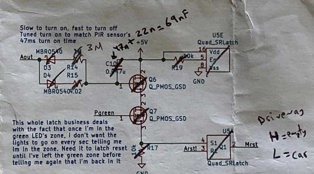
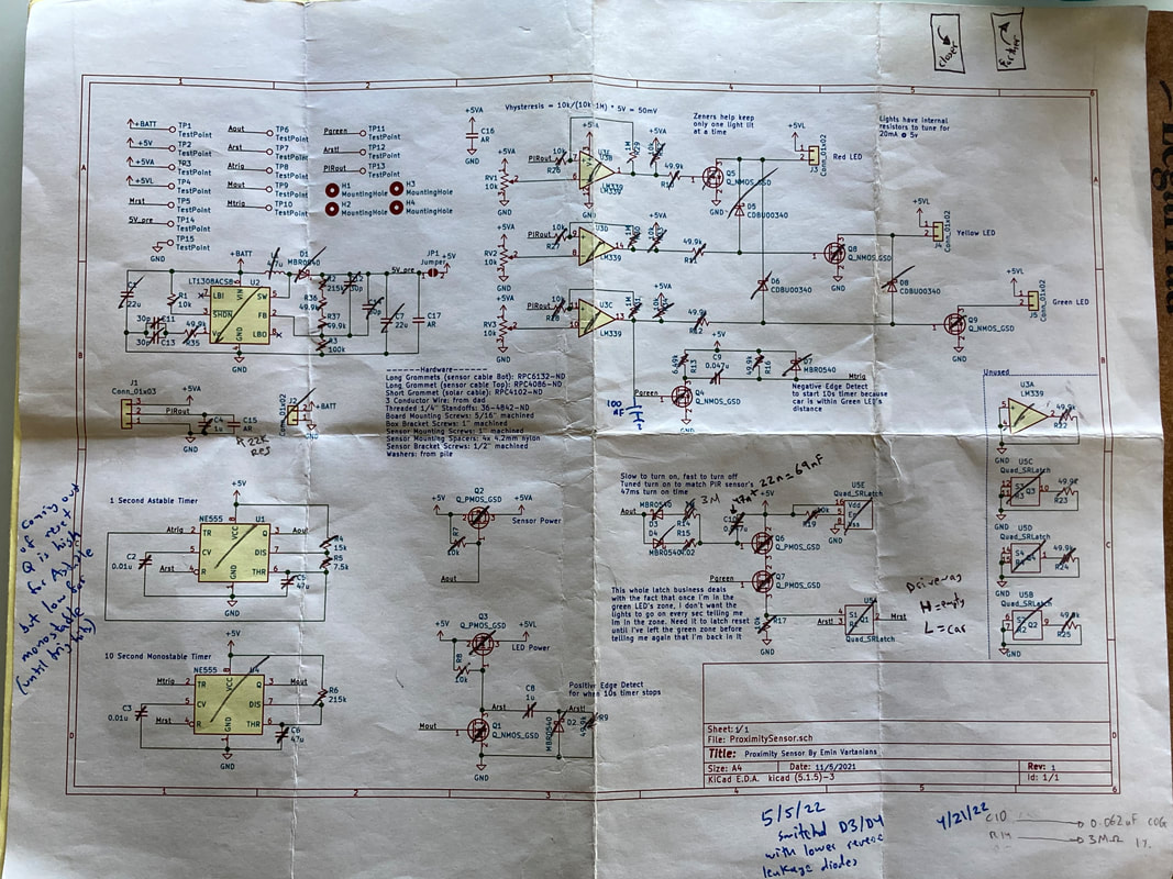
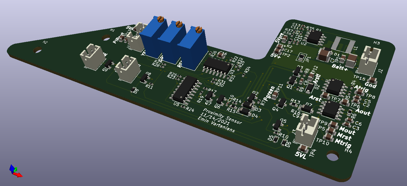
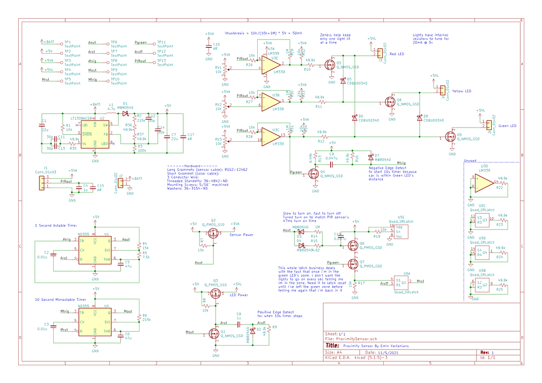
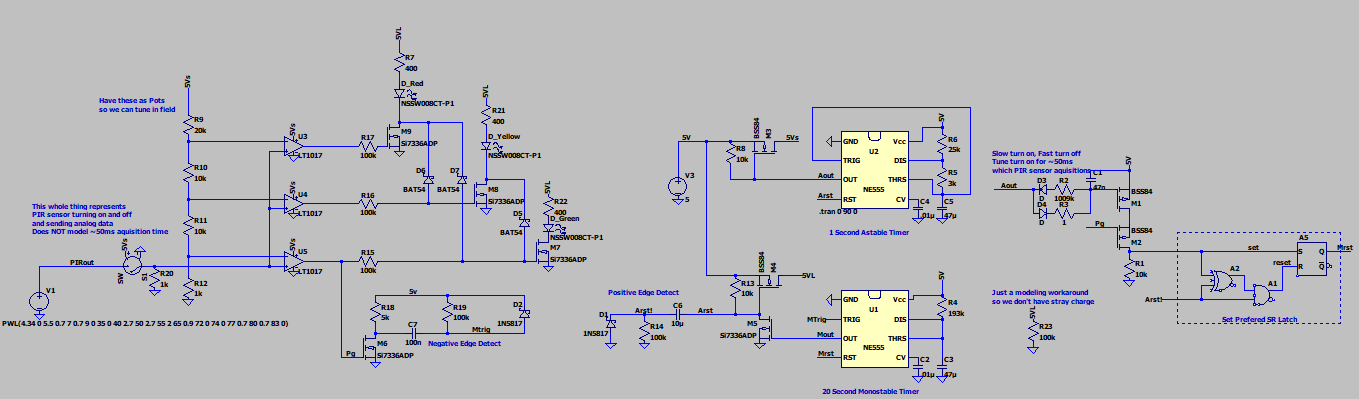
My marked up schematic for ref
| Feel free to look through the ScopePlots I captured. There's a readme file with the details. | ||
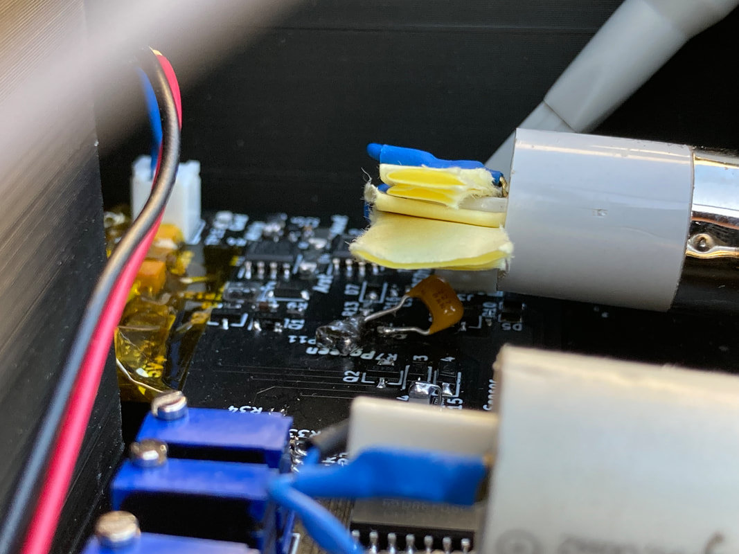
Then I realized a 2nd problem which was that every now and then, when the 5VA rail turns on at 1hz and powers the sensor and opamps, the opamp's output rises just a little for a split second. Most of the time it's harmless, but sometimes it puts Pgreen high enough to turn on Q4 which produces the Monostable (10s) timer's trigger. This had the affect of putting the sensor in a "there's a car in the driveway" state which means it stays on for 10s and shows you the car's distance with the lights, but because there was no car there it would stay off and just drain the battery with the 10s of on time. This also explained why sometimes as I pulled into the driveway the lights would come on and show the distance but would shut off quicker than 10s. I figured this is somewhat due to turn on transients inside the opamp and the fact that I have a high impedance load on the opamp at low voltages so I just wacked a 100nF cap that I had laying around on Pgreen to ground which could absorb the transient energy and keep Pgreen low so Mtrig wouldn't pulse and start the 10s timer. this does technically mean that Pgreen responds slower to a legitimate proximity signal but in practice it was fast enough for my purpose that I don't see the difference. Now, the sensor behaves just as expected.
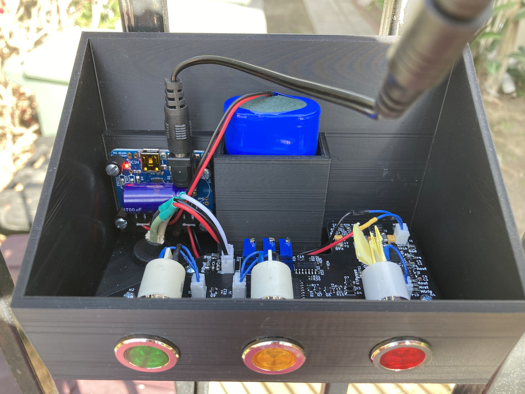
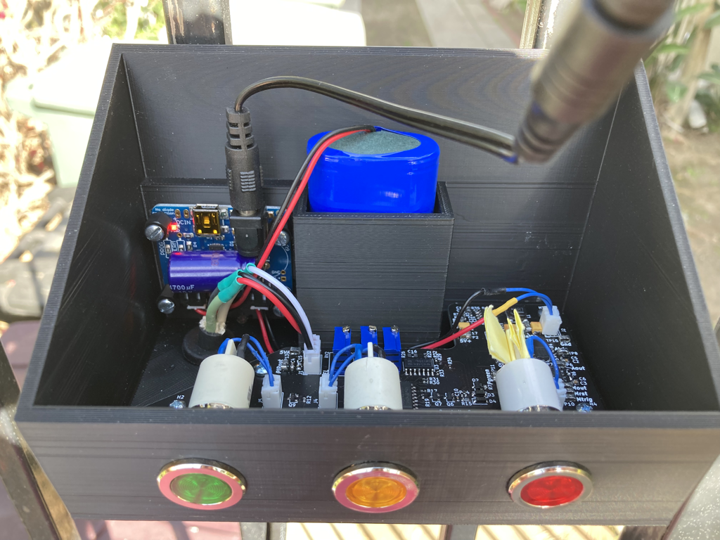
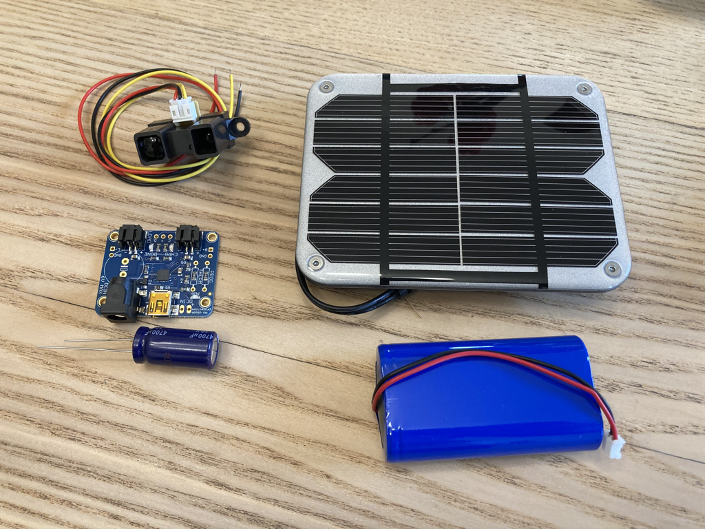
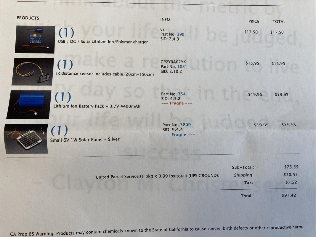
While debugging I did notice that the original solar charging board I had bought from Adafruit would peg the output voltage to the panel voltage which was unexpected (though it is in their documentation, I just overlooked it). So the voltage coming into my board was anywhere between 3.2v on an almost dead battery, to 4.19v on an almost fully charged battery, to 6v when the battery is full and the panel is illuminated. This meant that on sunny days when my board was receiving 6v my boost converter which expected 4.2v max from the battery/charger was receiving 6v, not being able to produce a negative PWM somehow and just passing the 6v out to the my 5v rails. Nothing was damaged but I didn't like it, and it made my capacitor discharge measurements and theories even more muddy. Adafruit now sells a much more practical solar charger that outputs 5v regardless of the battery SoC and panel power, so I switched that guy in.
While debugging I did notice that the original solar charging board I had bought from Adafruit would peg the output voltage to the panel voltage which was unexpected (though it is in their documentation, I just overlooked it). So the voltage coming into my board was anywhere between 3.2v on an almost dead battery, to 4.19v on an almost fully charged battery, to 6v when the battery is full and the panel is illuminated. This meant that on sunny days when my board was receiving 6v my boost converter which expected 4.2v max from the battery/charger was receiving 6v, not being able to produce a negative PWM somehow and just passing the 6v out to the my 5v rails. Nothing was damaged but I didn't like it, and it made my capacitor discharge measurements and theories even more muddy. Adafruit now sells a much more practical solar charger that outputs 5v regardless of the battery SoC and panel power, so I switched that guy in.
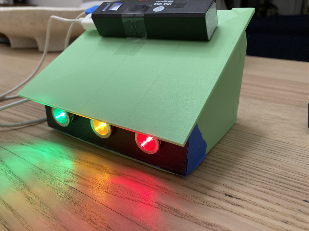
And that's it folks! the sensor has been working well for a few weeks now, just charges up during the day and discharges at night. Have no had an event where it discharged all the way yet, maybe in the winter when the sun is out less but I down that still. Unless something happens, this'll be the last post for the project so I can move on to other things. Hope you had fun reading about it because I had fun making it.