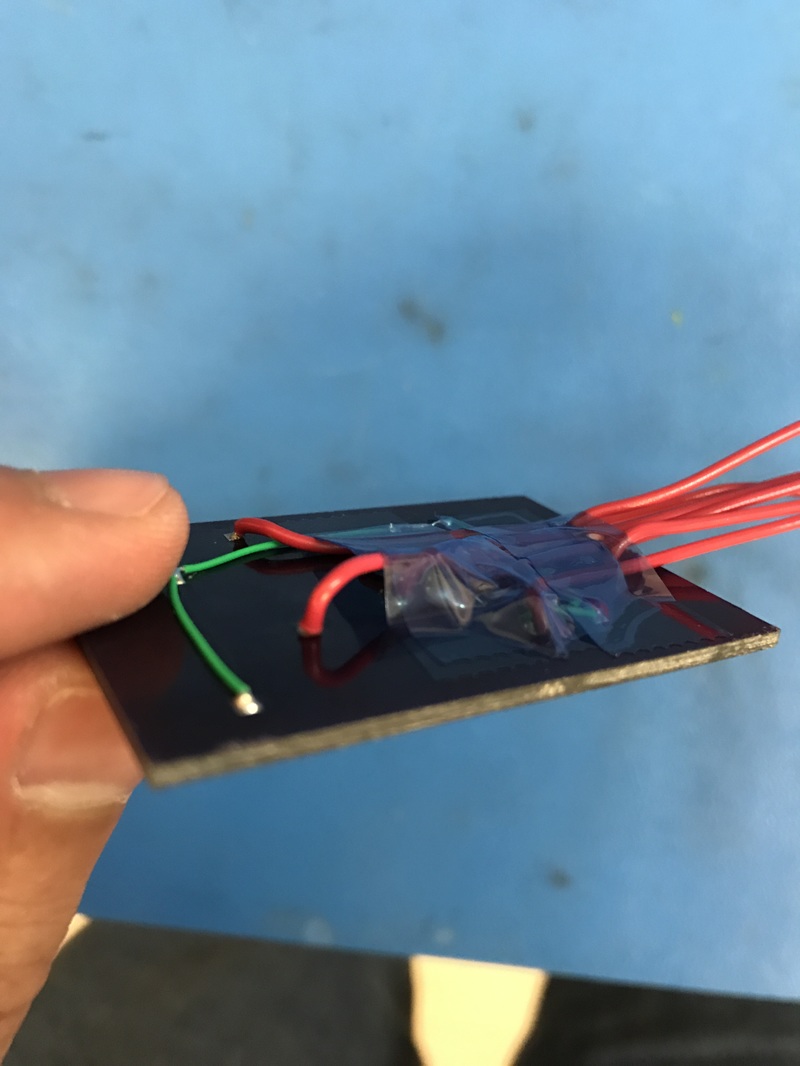
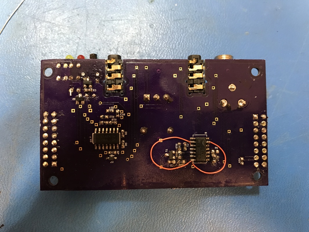
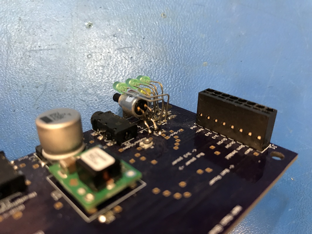
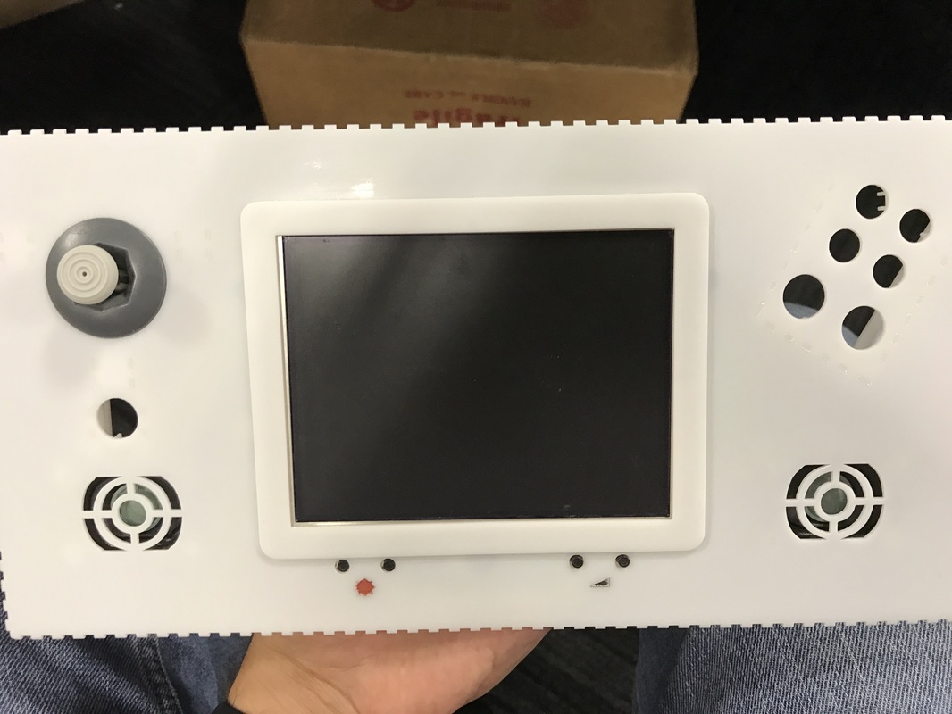
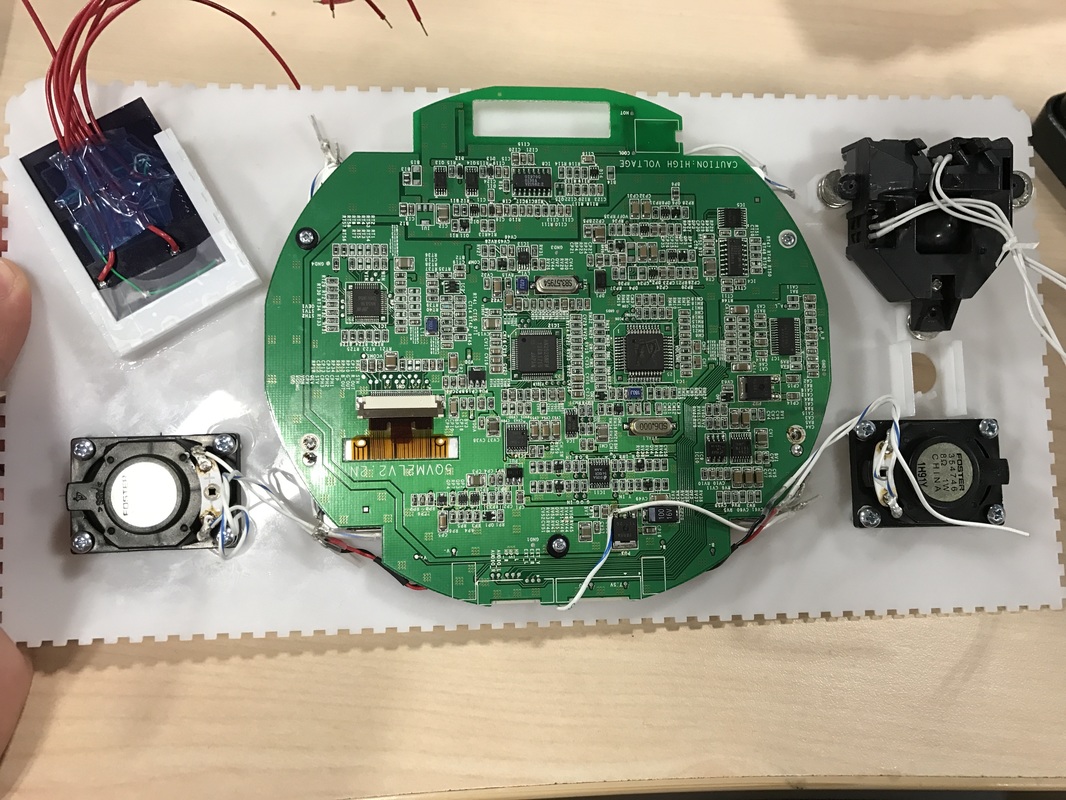
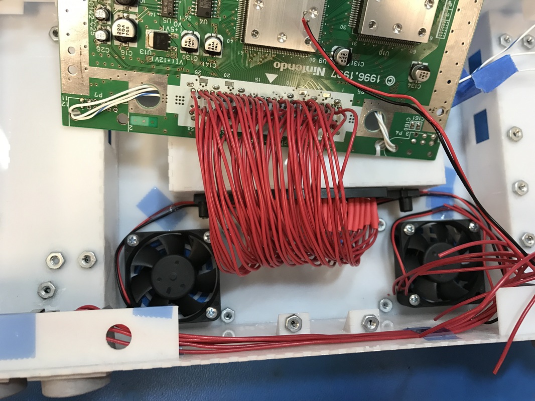
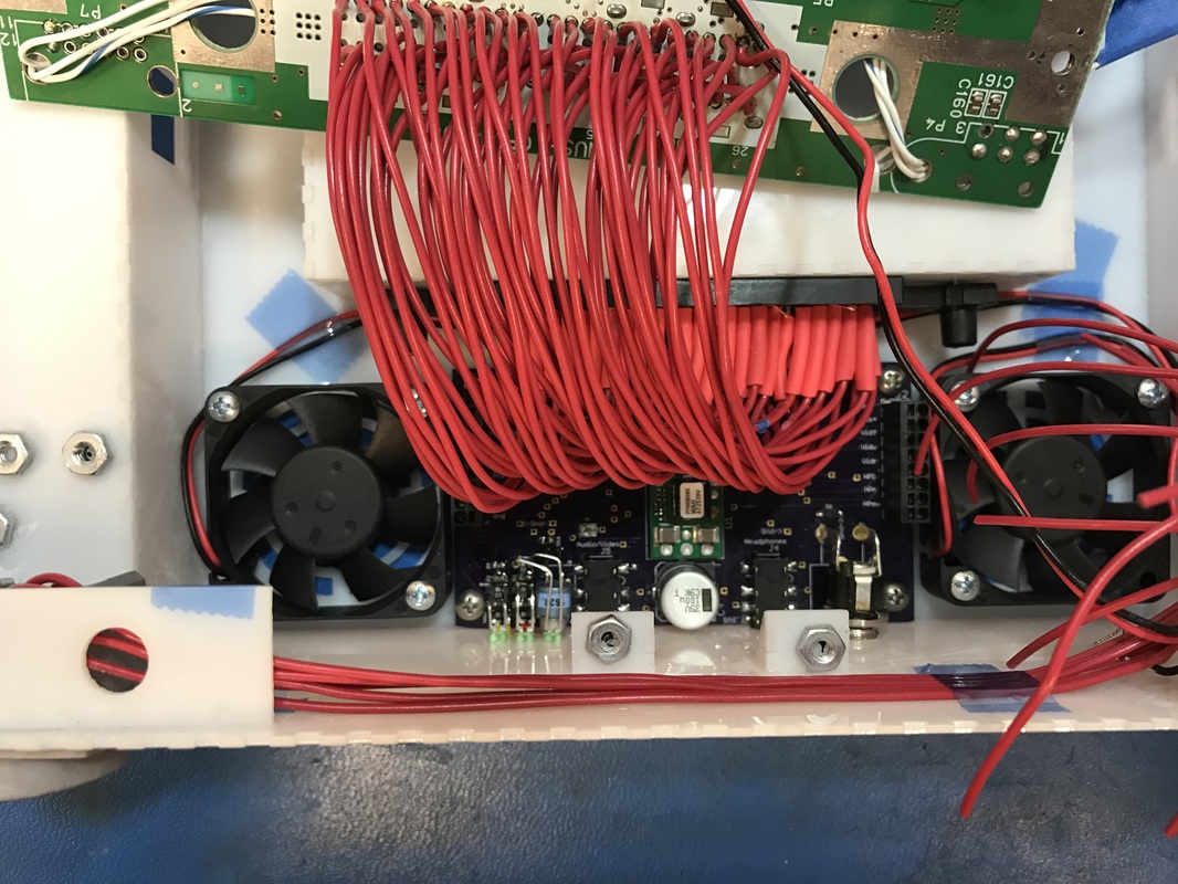
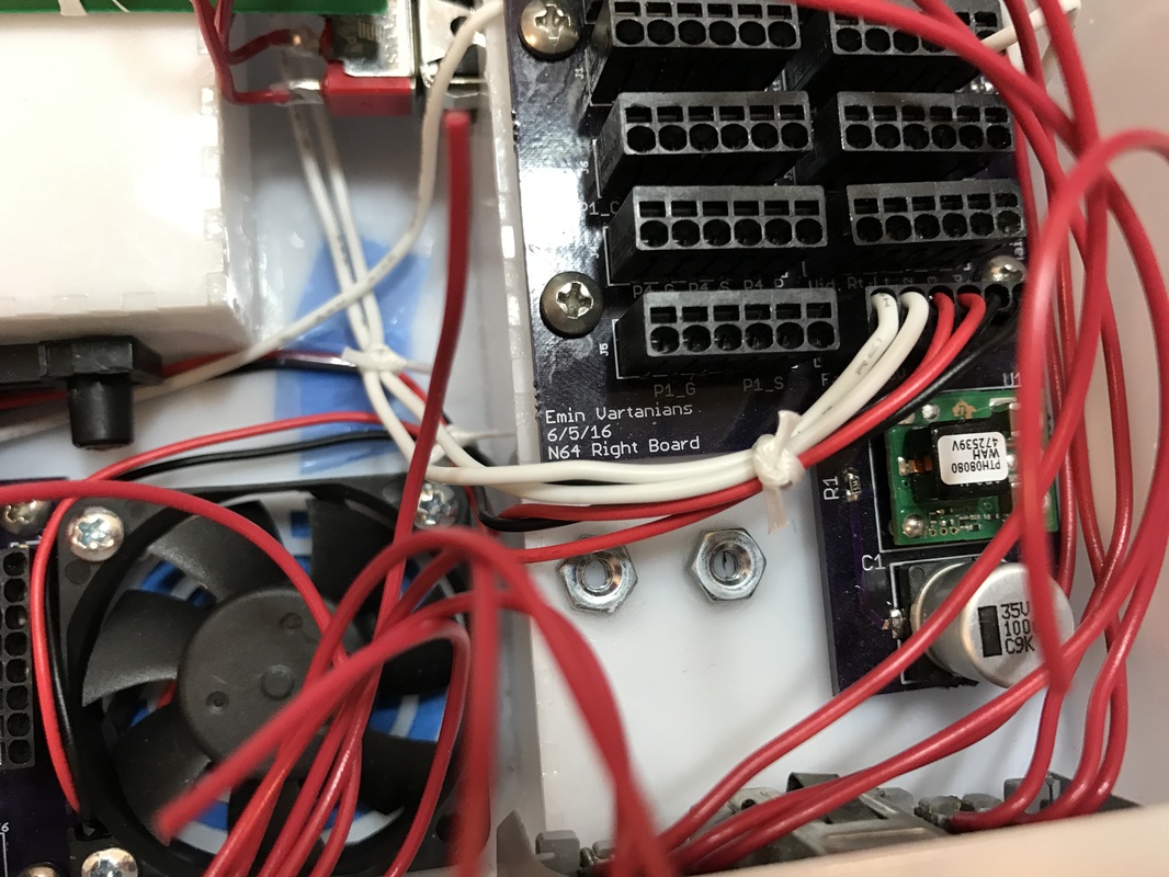
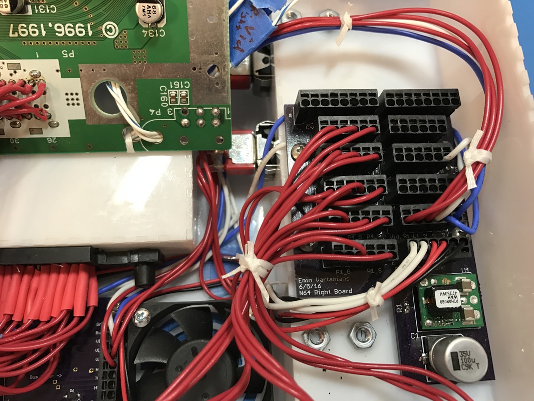
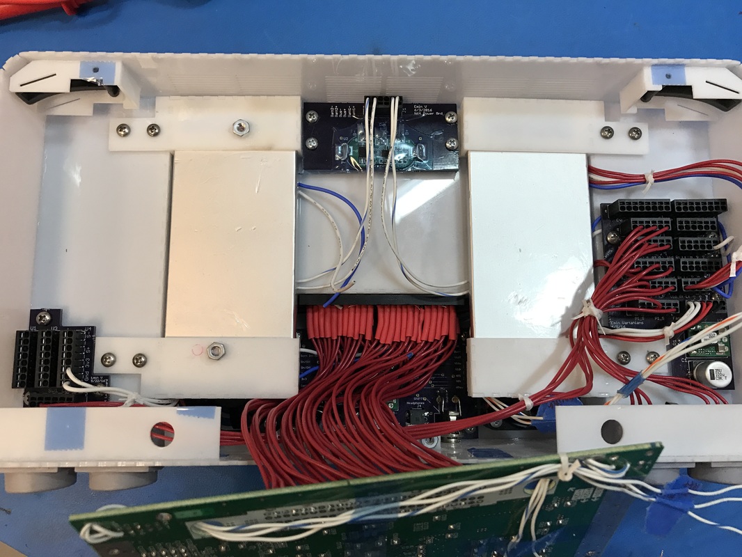
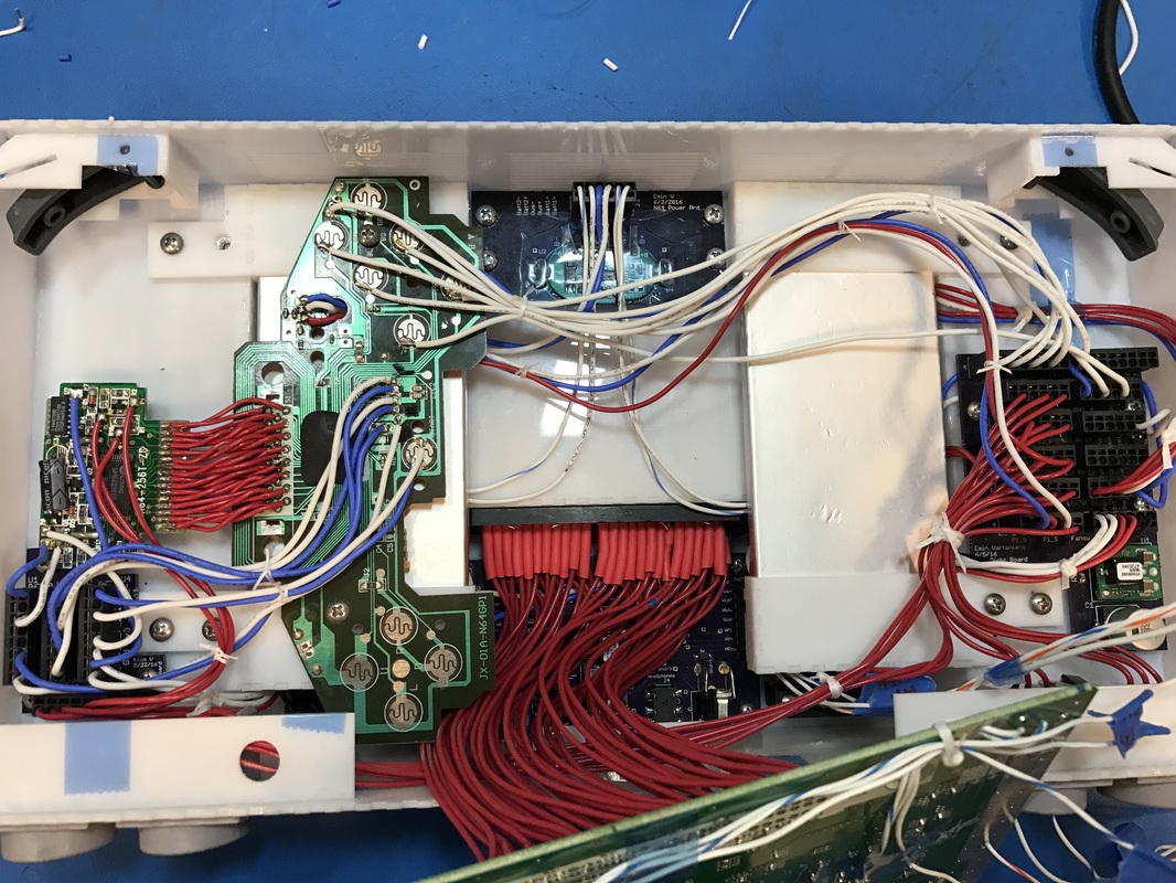
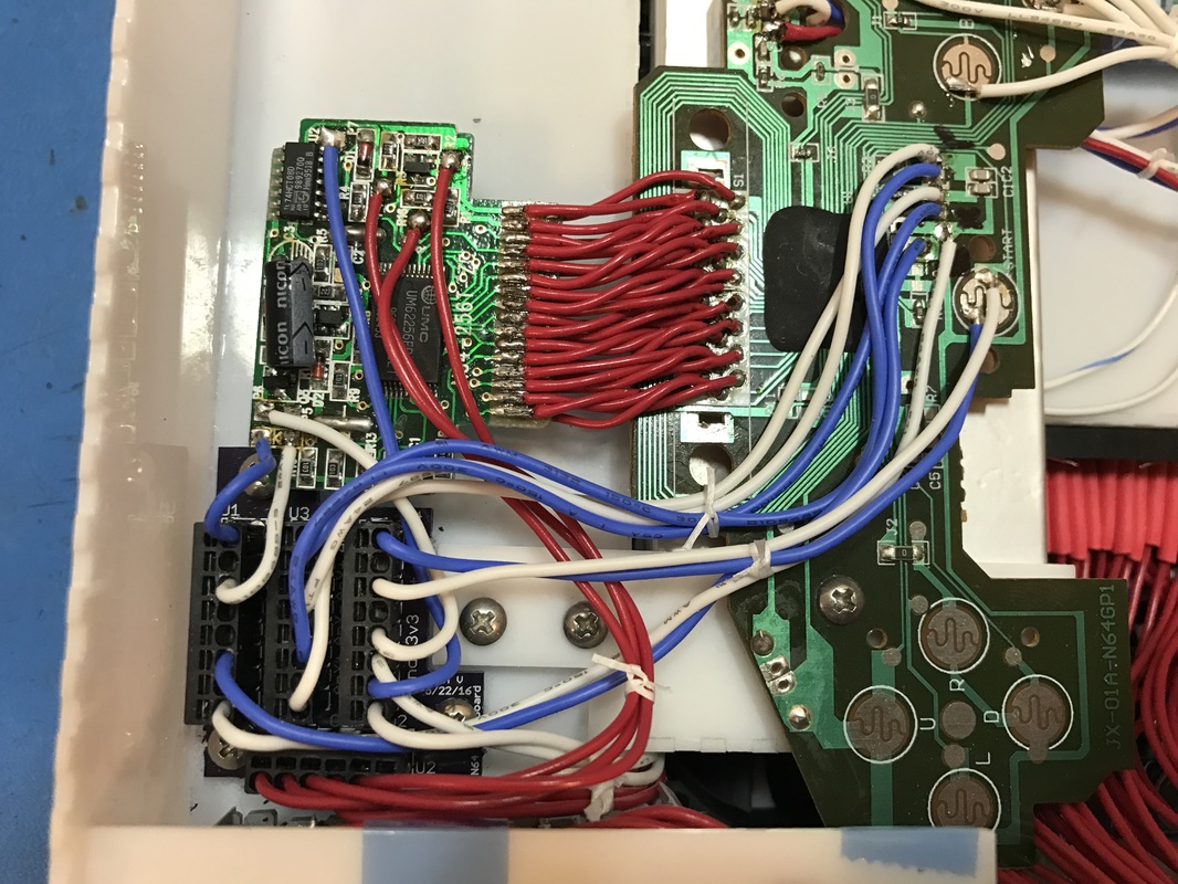
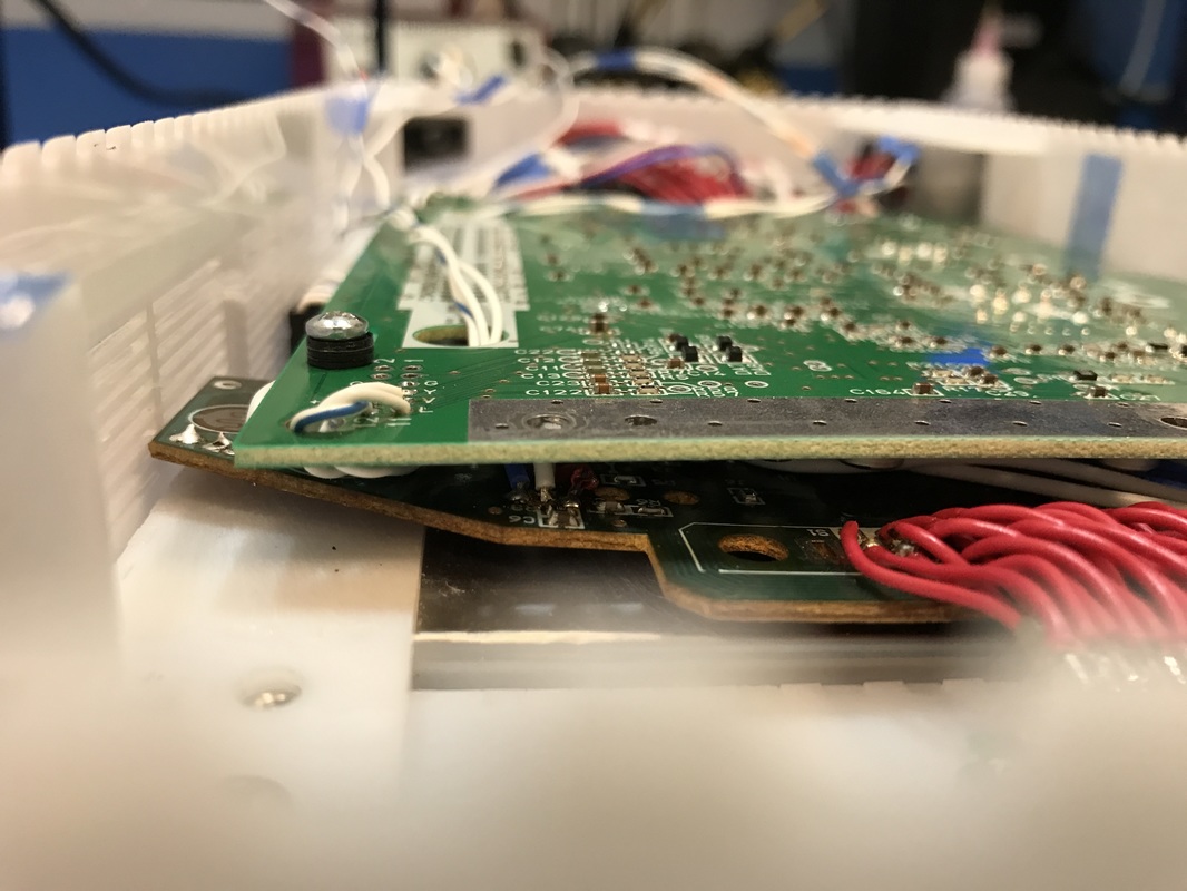
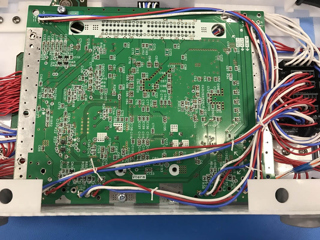
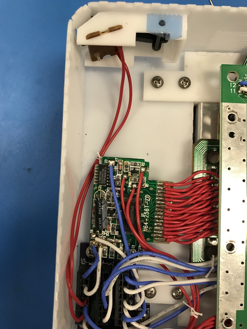
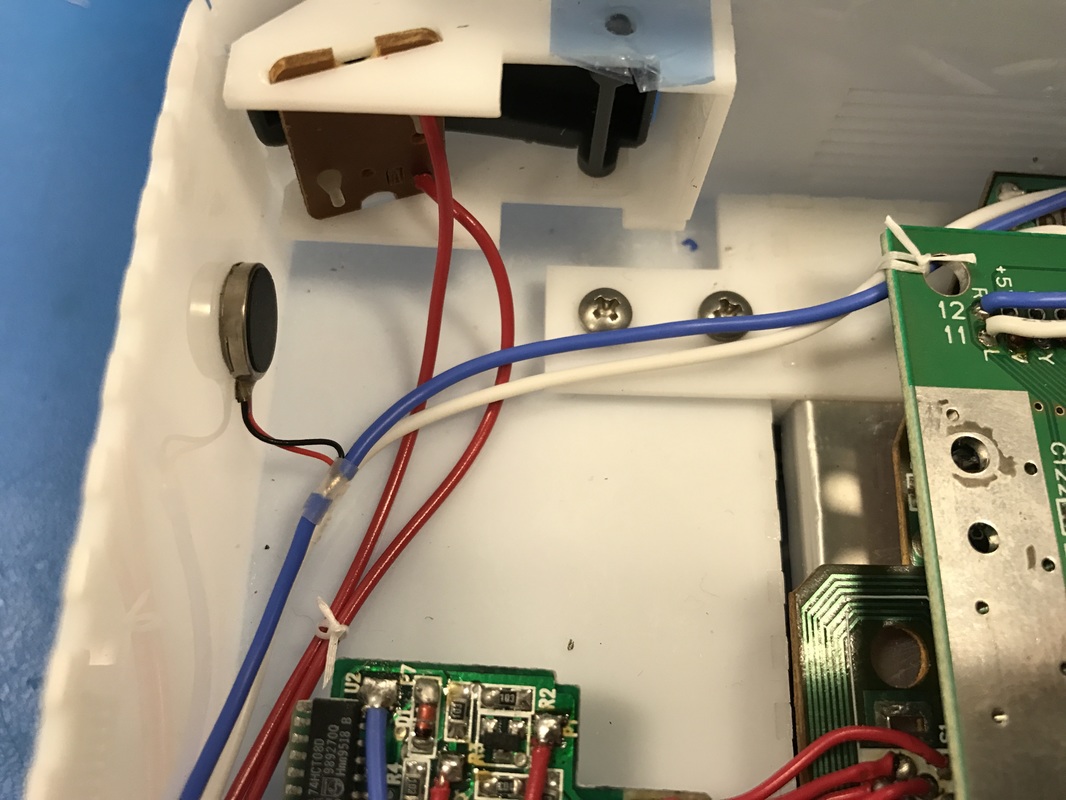
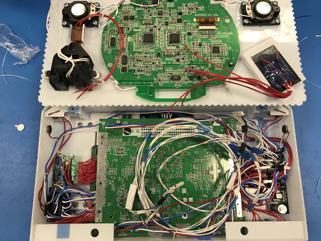
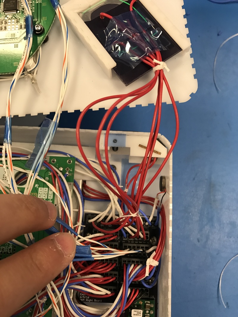
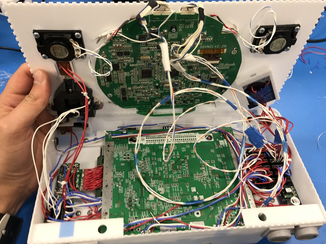
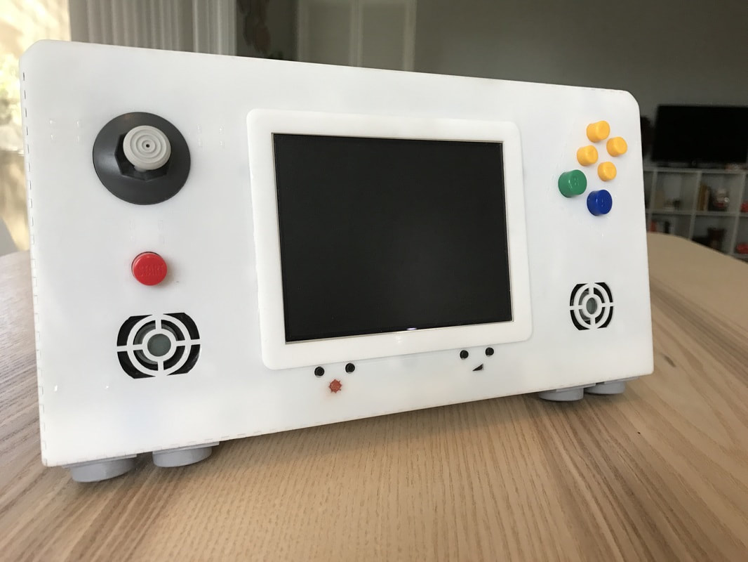
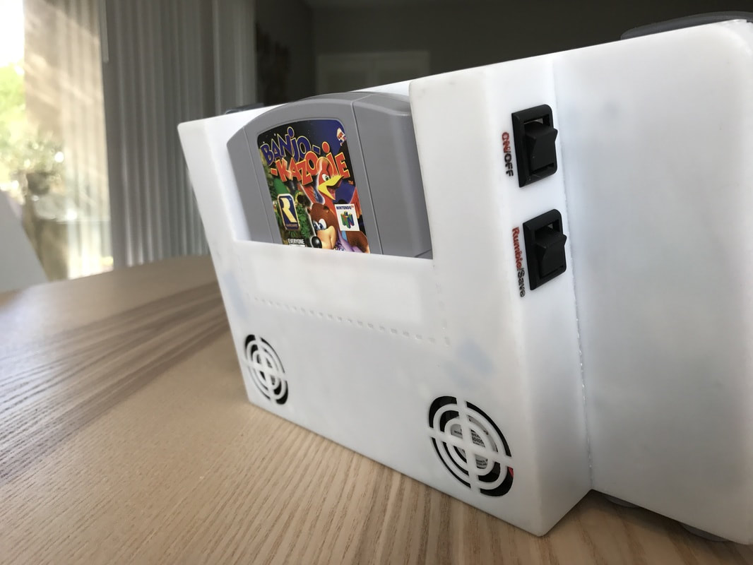
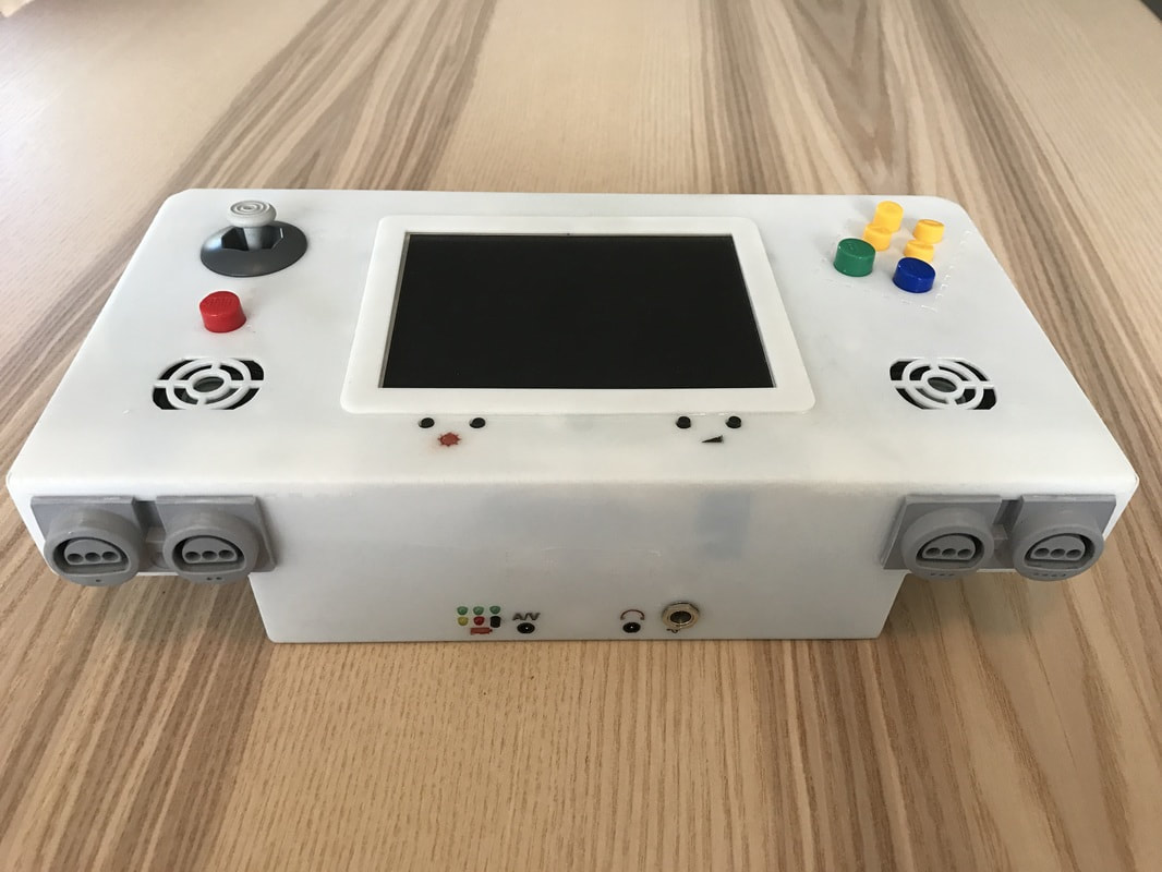
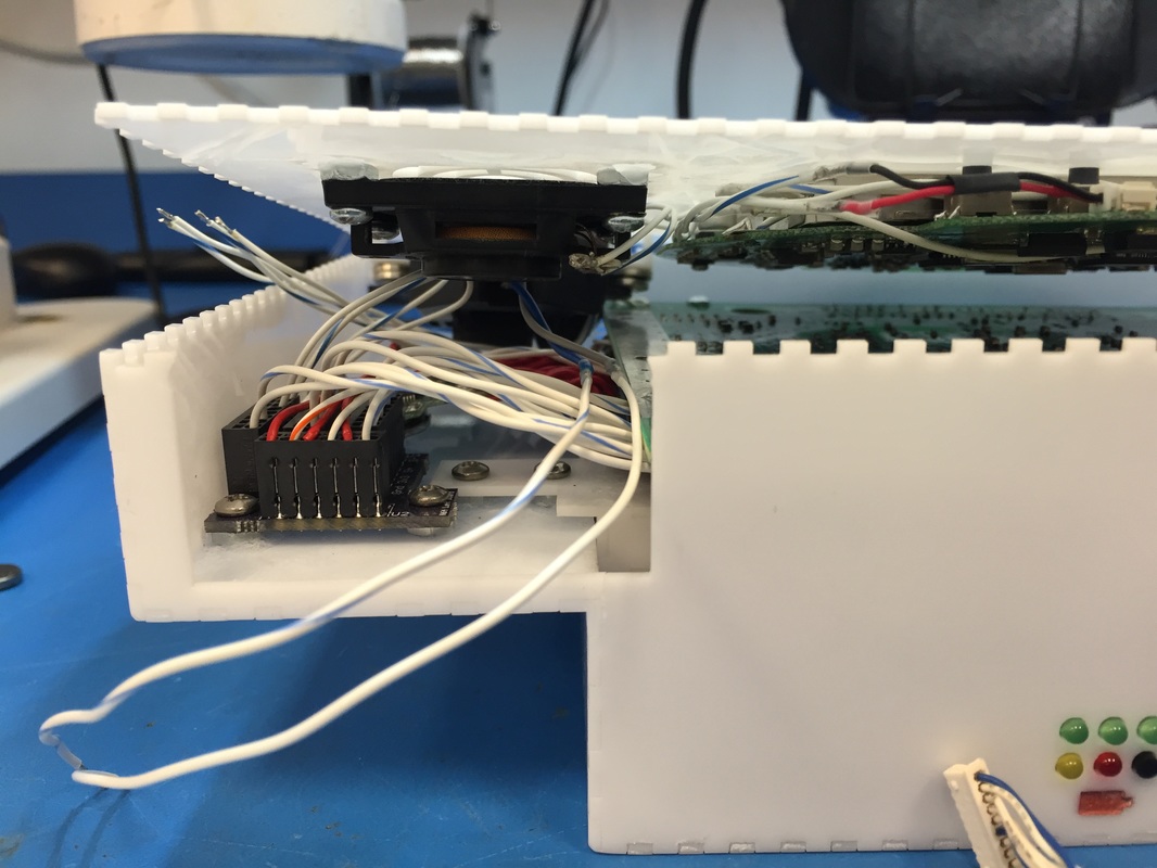
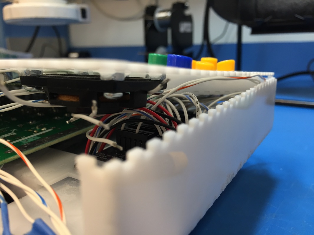
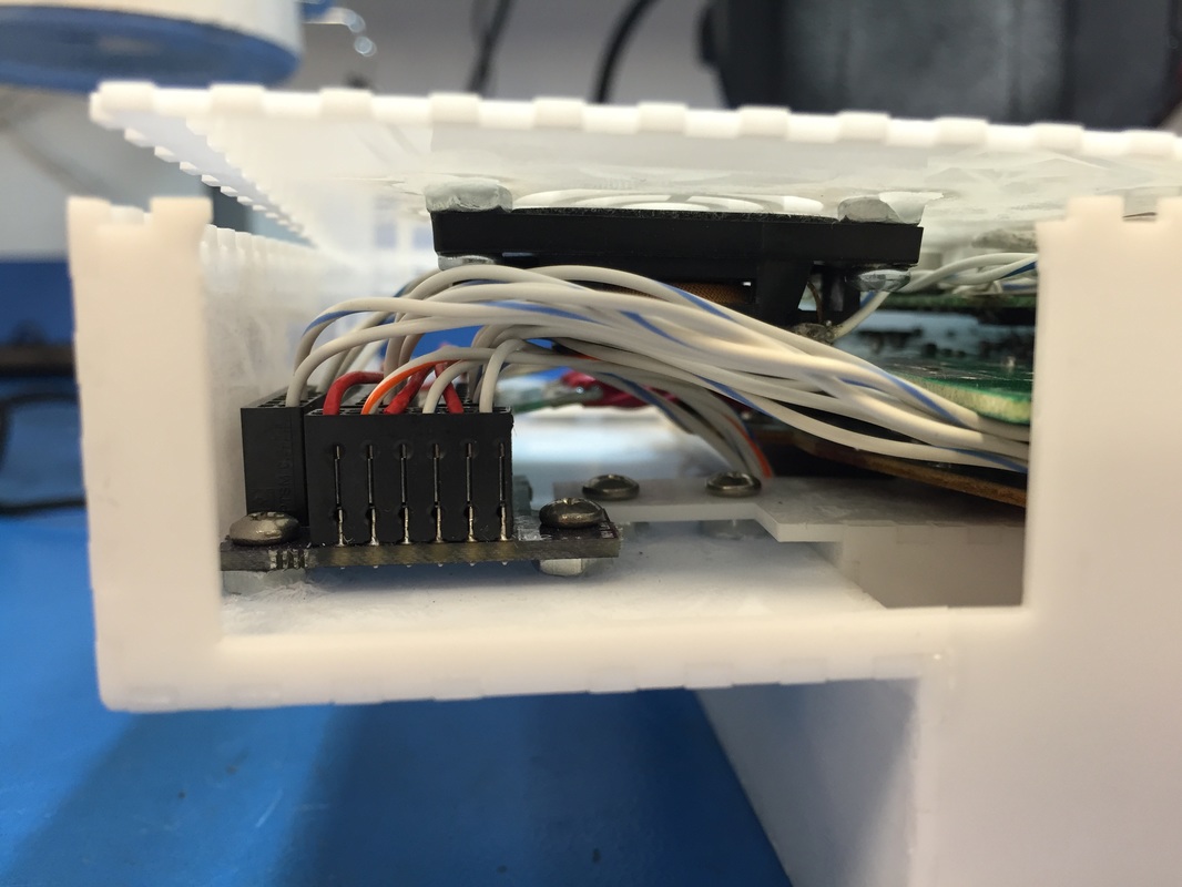
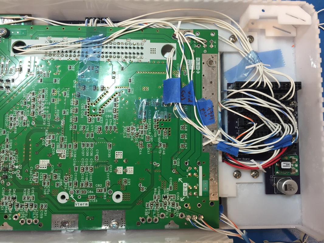
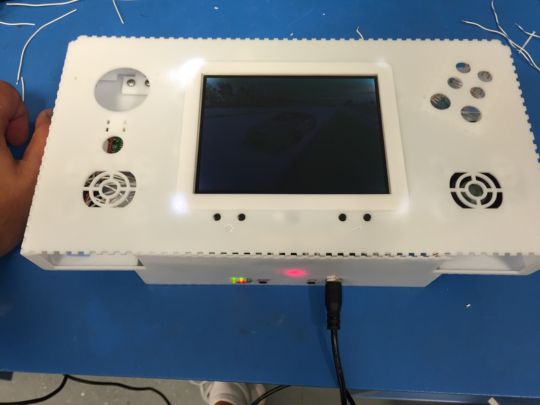
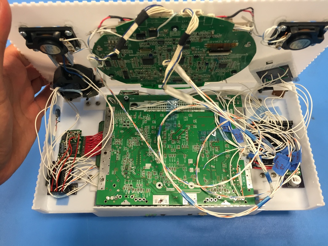
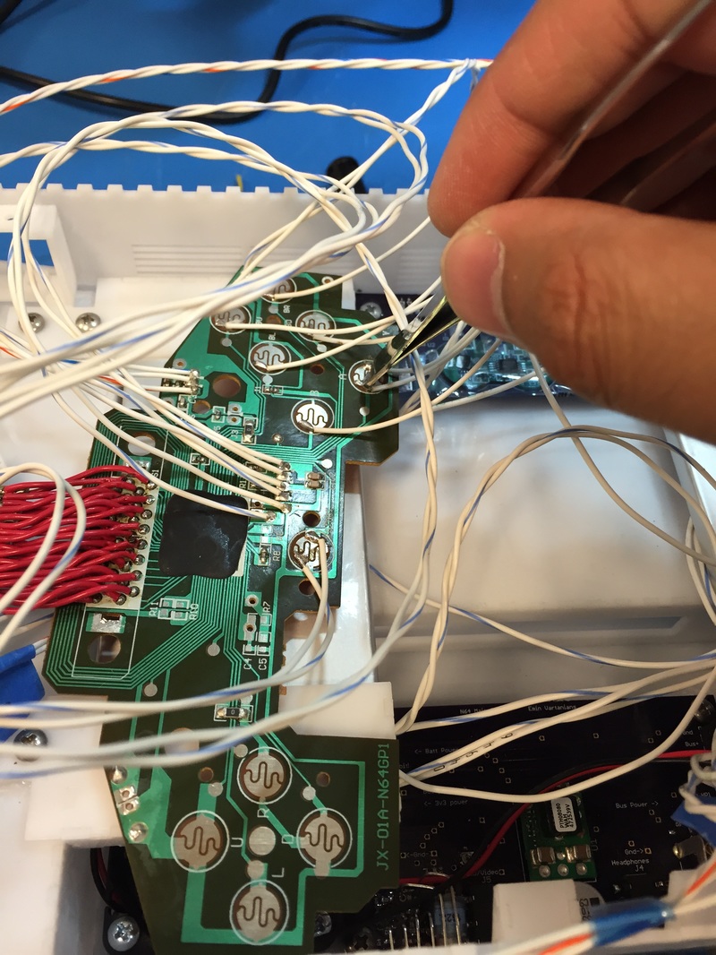
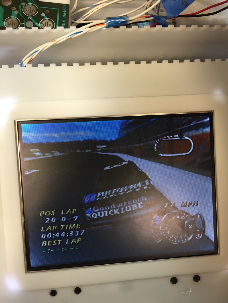
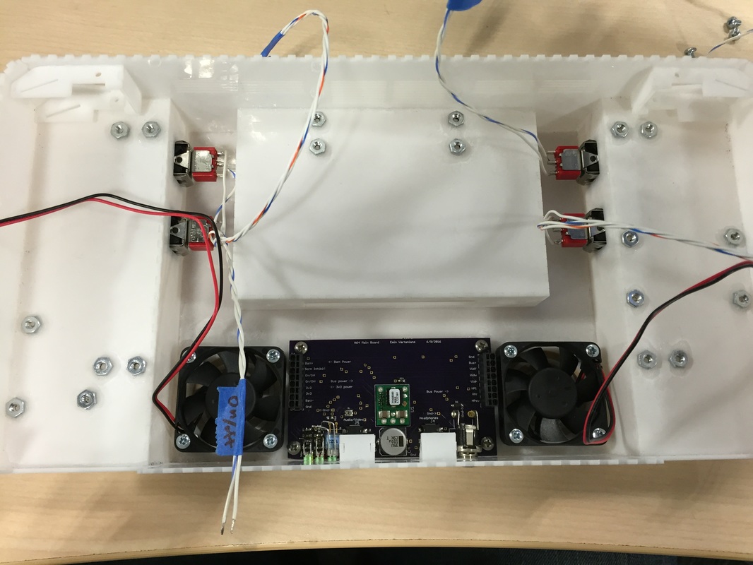
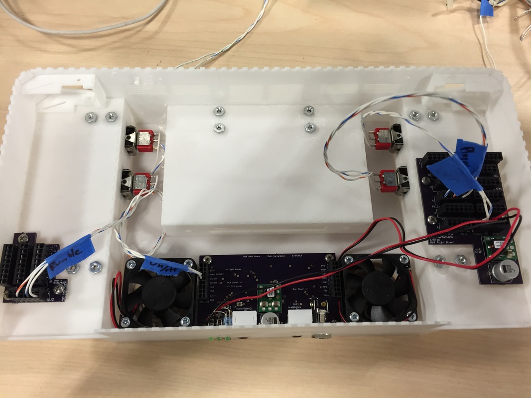
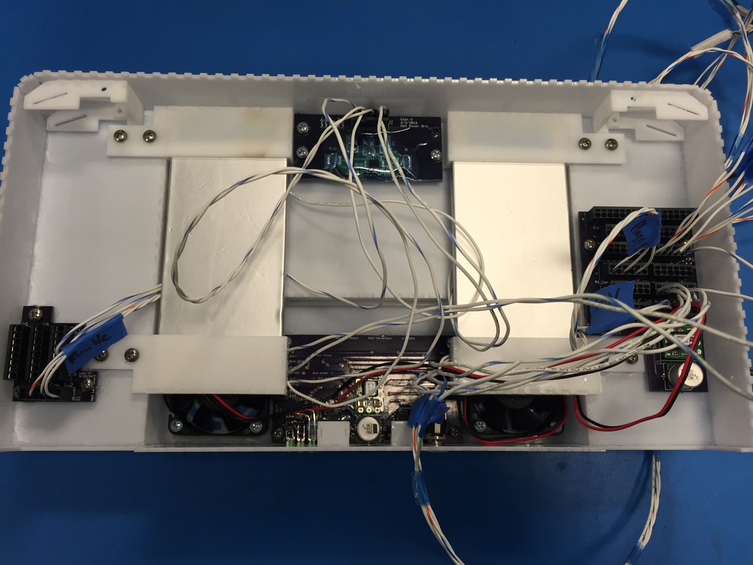
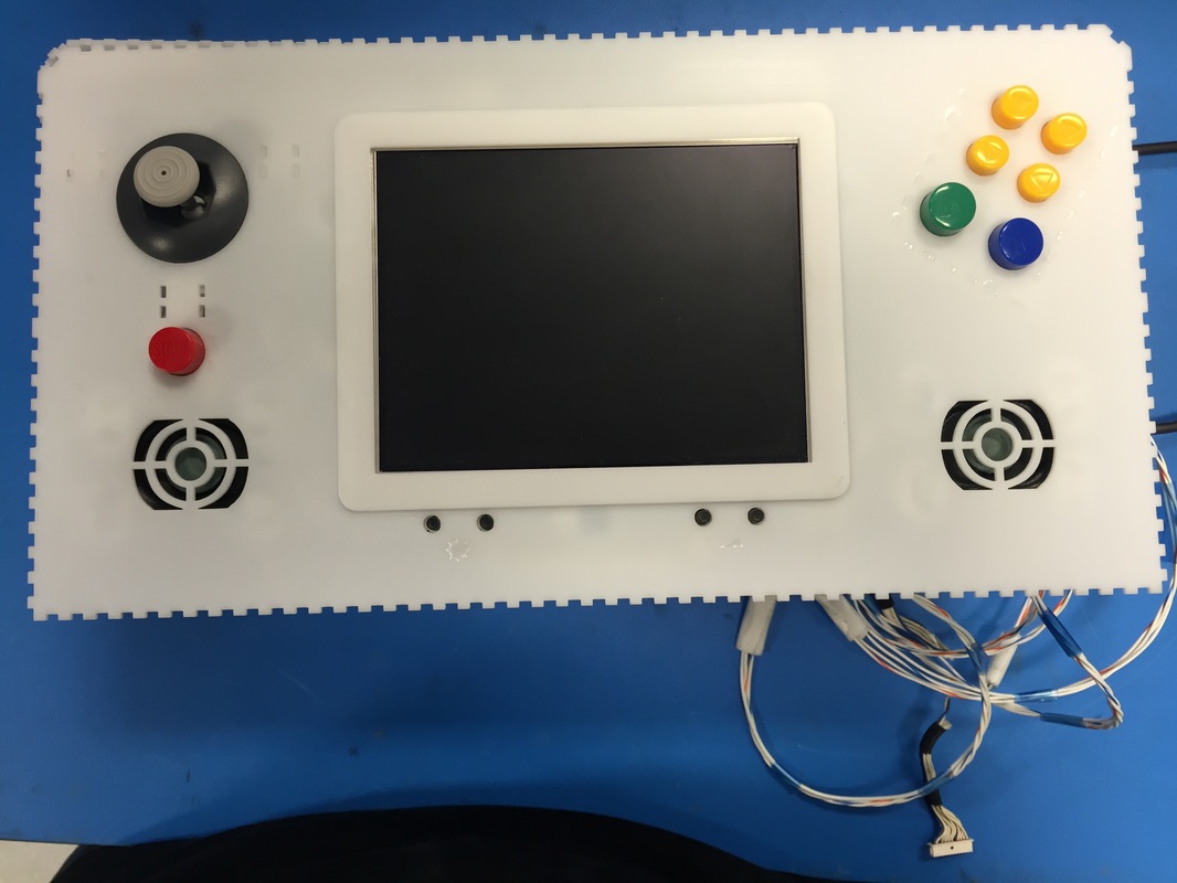
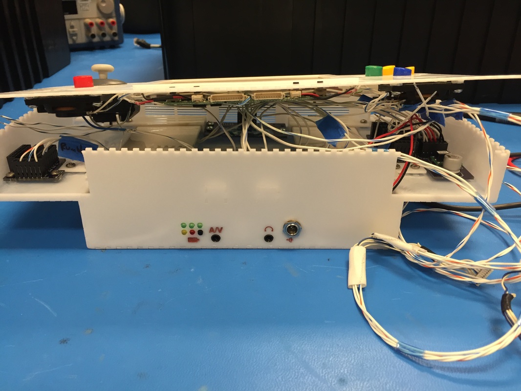
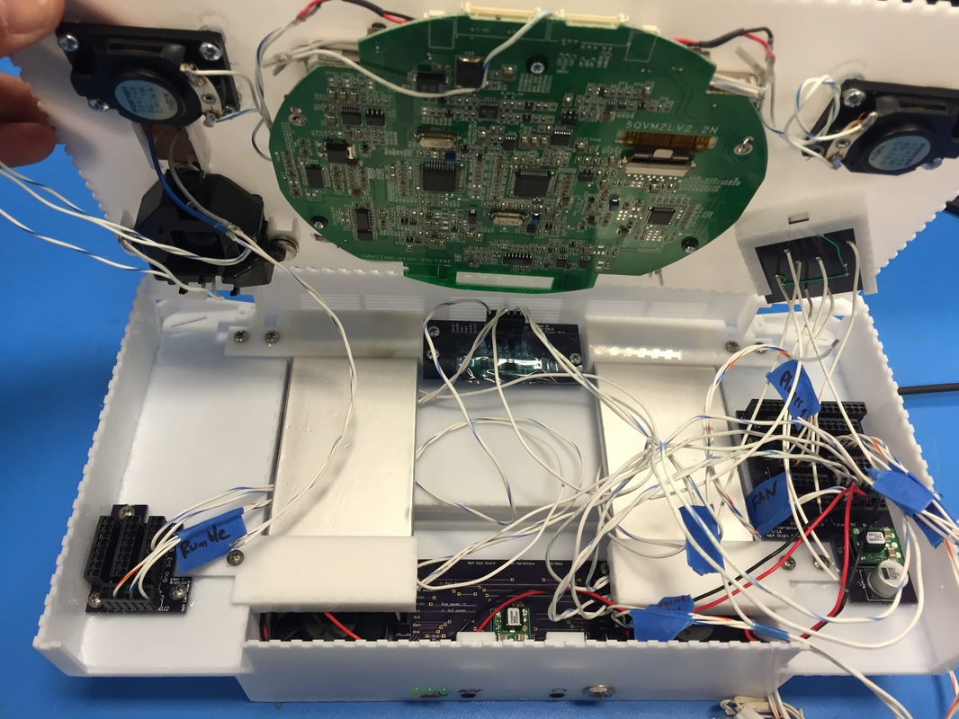
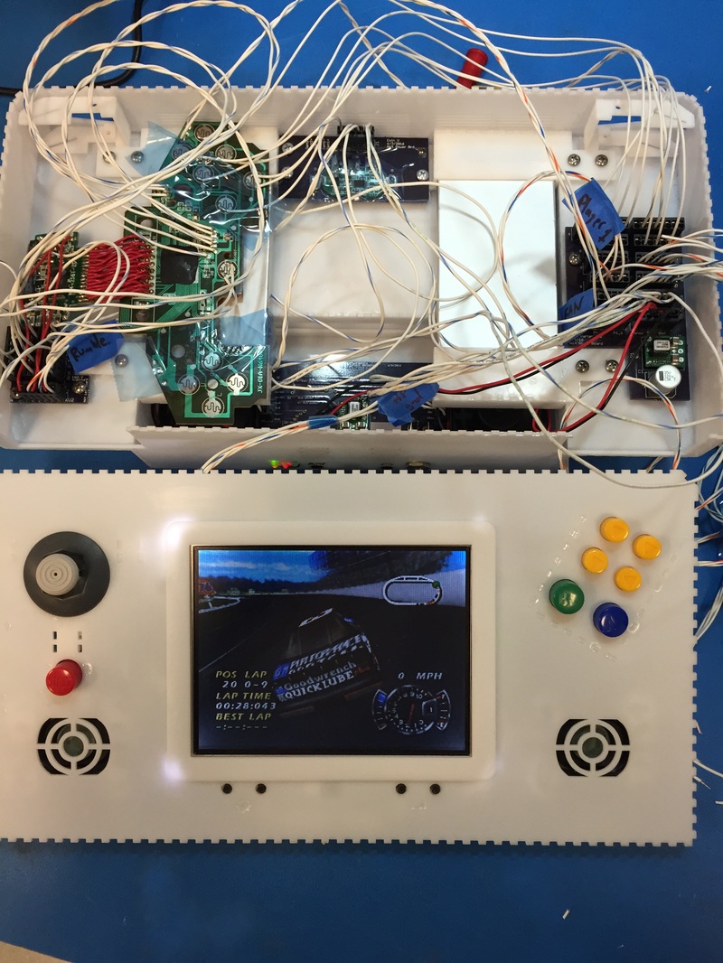
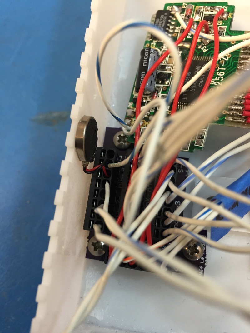
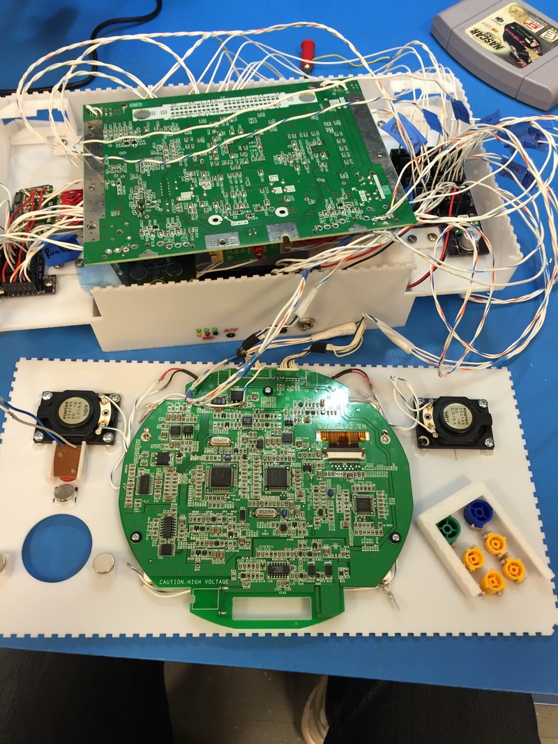
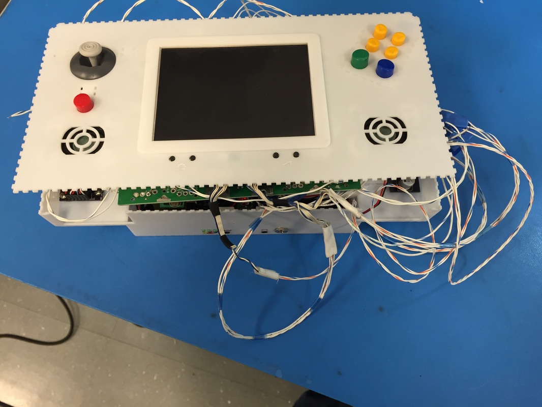
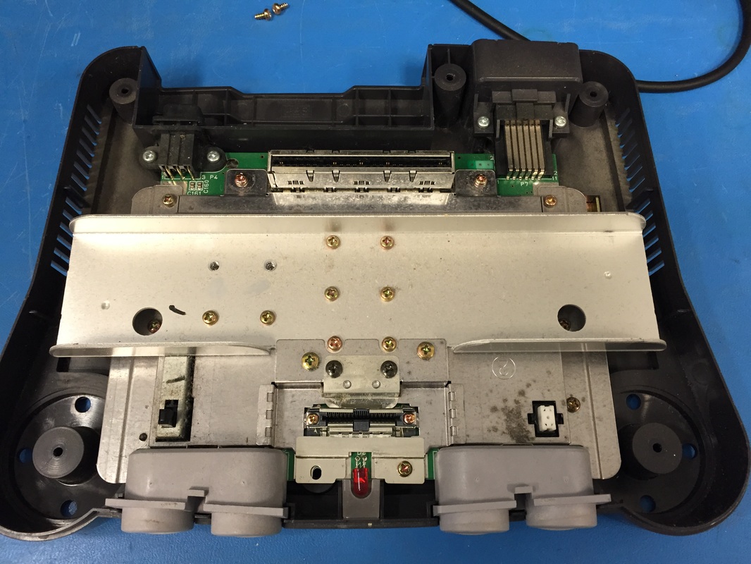
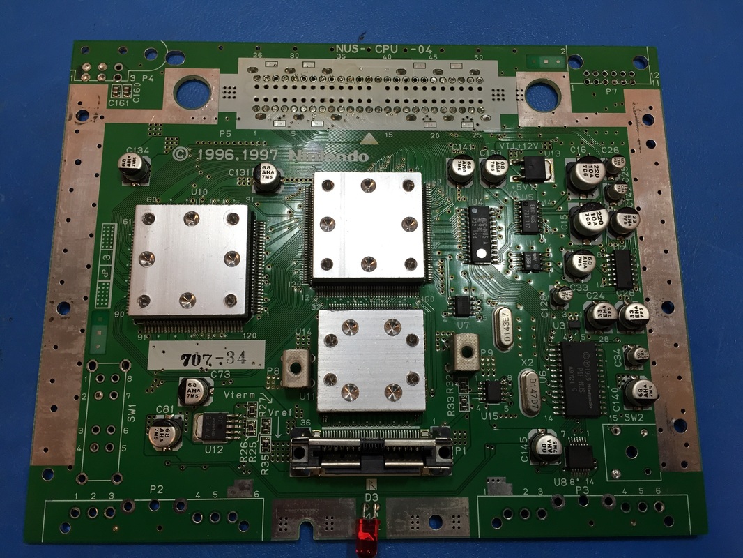
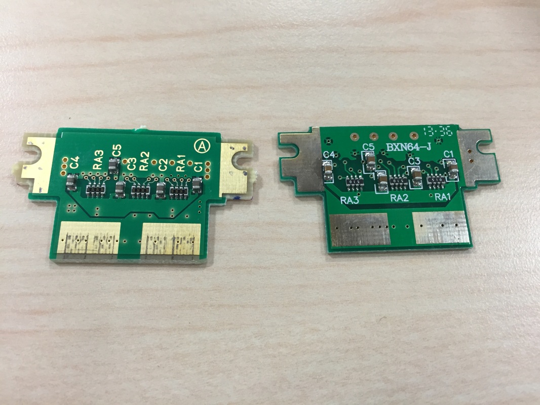
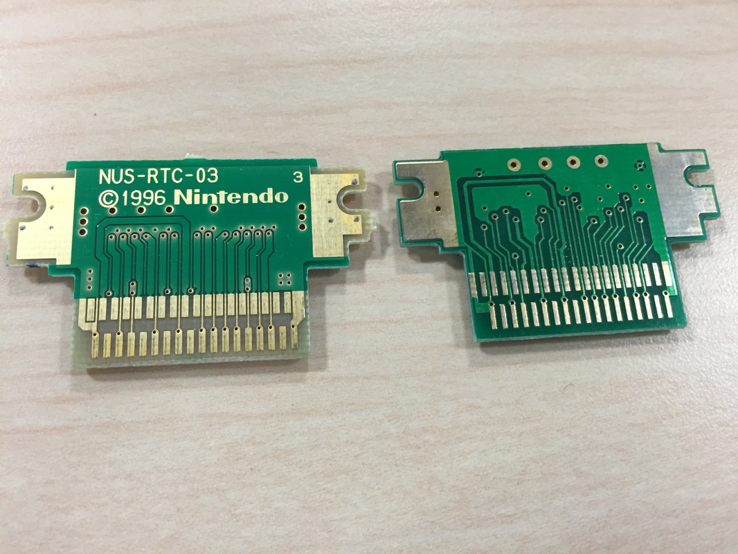
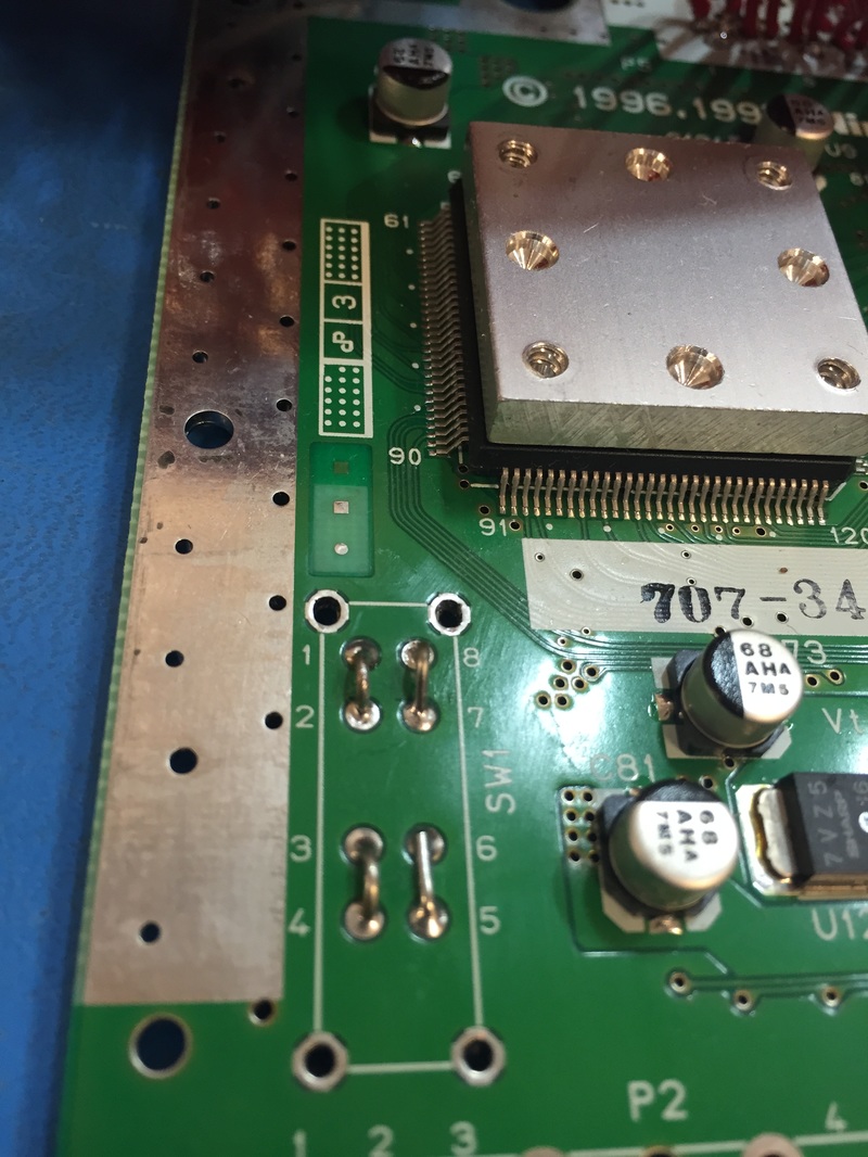
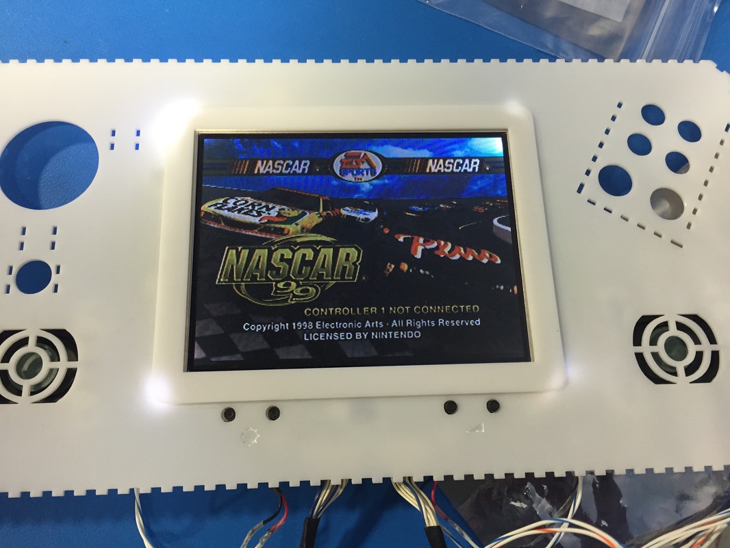
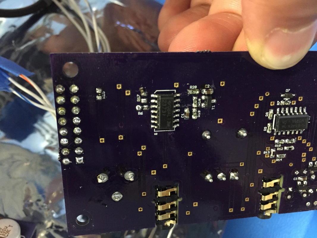
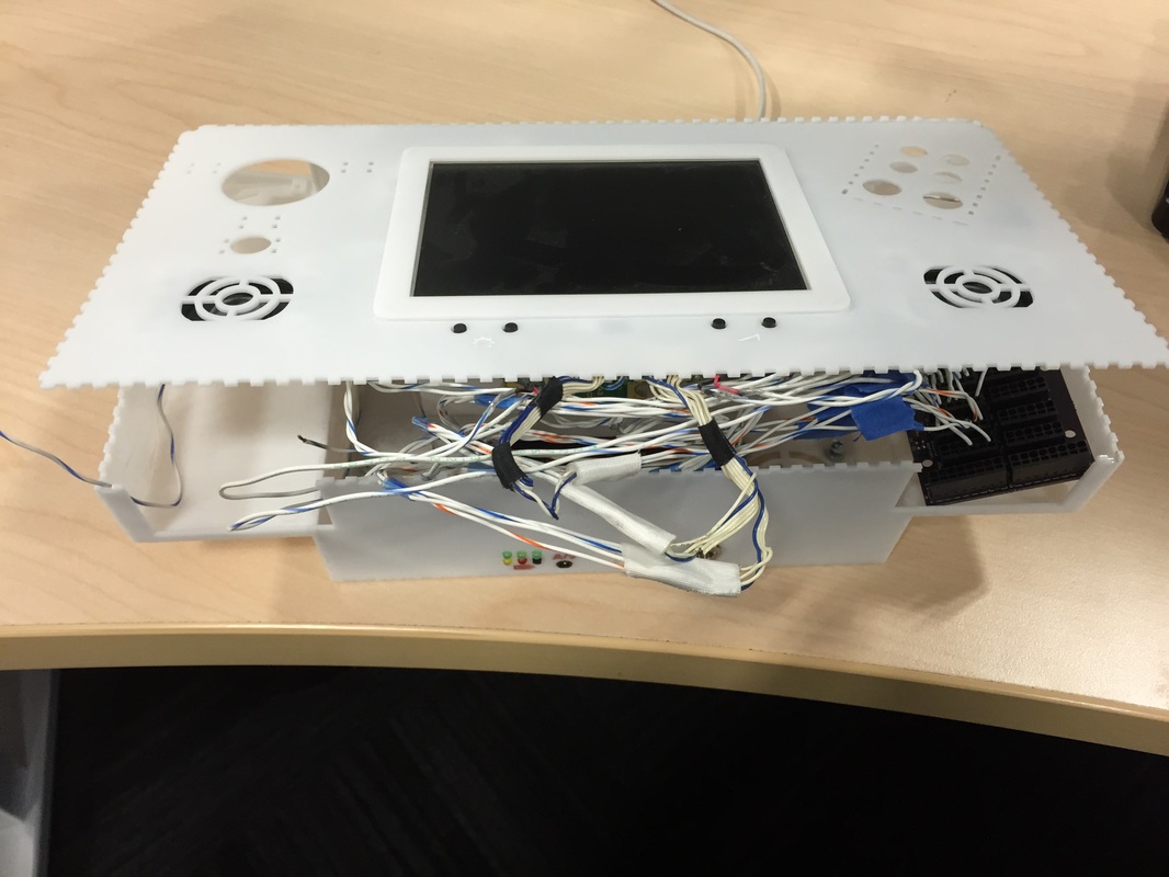
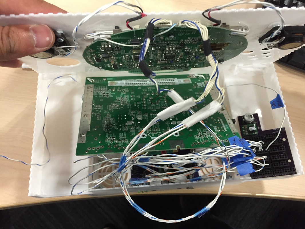
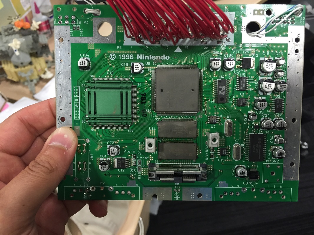
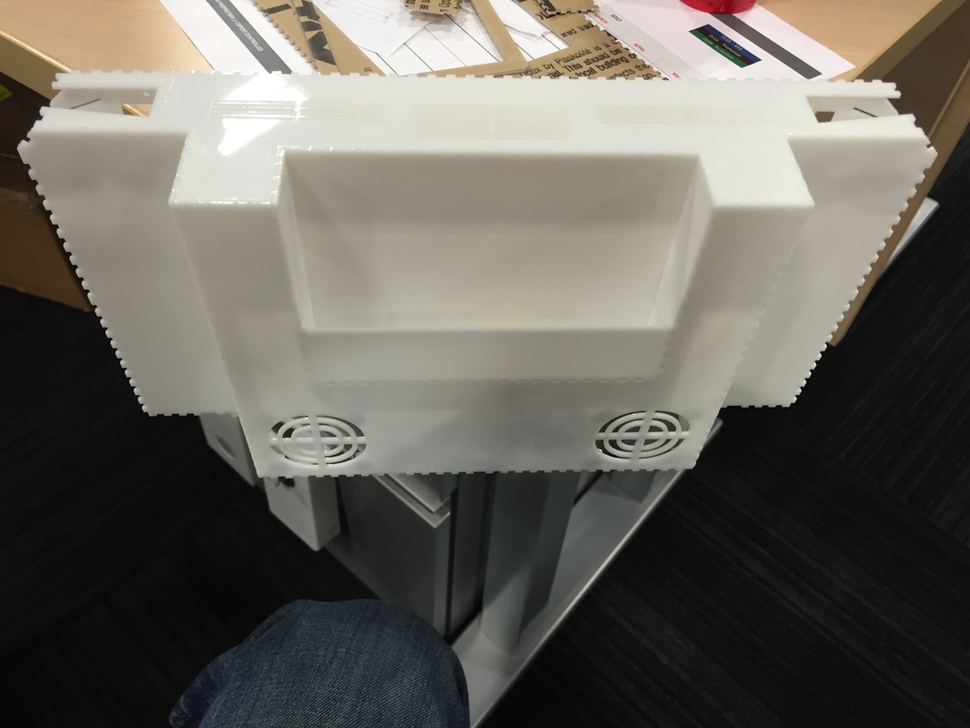
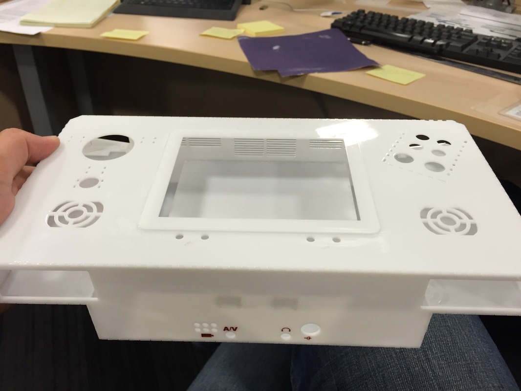
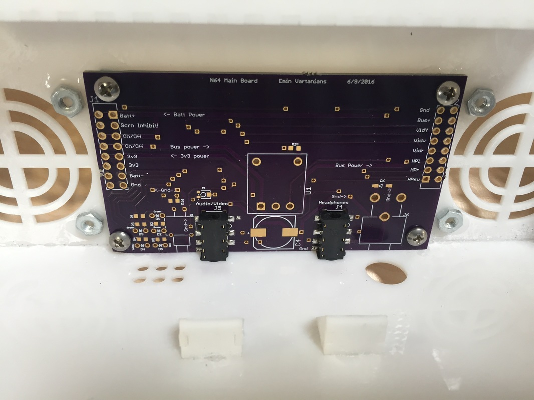
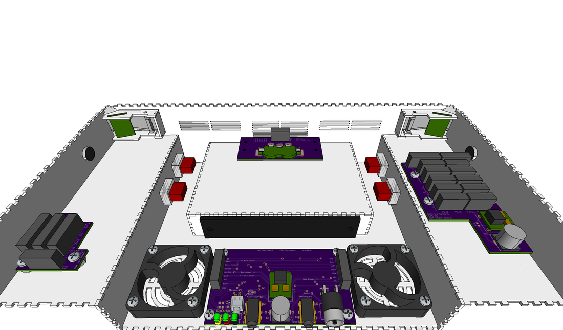
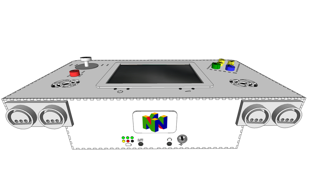
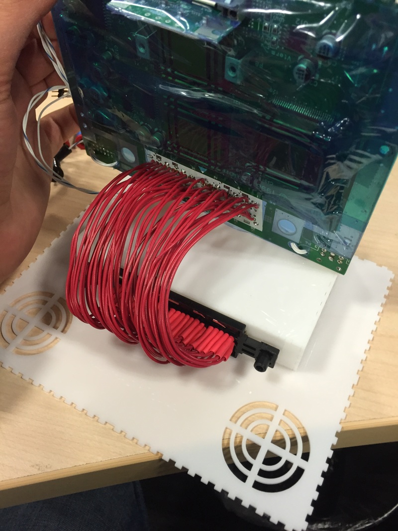
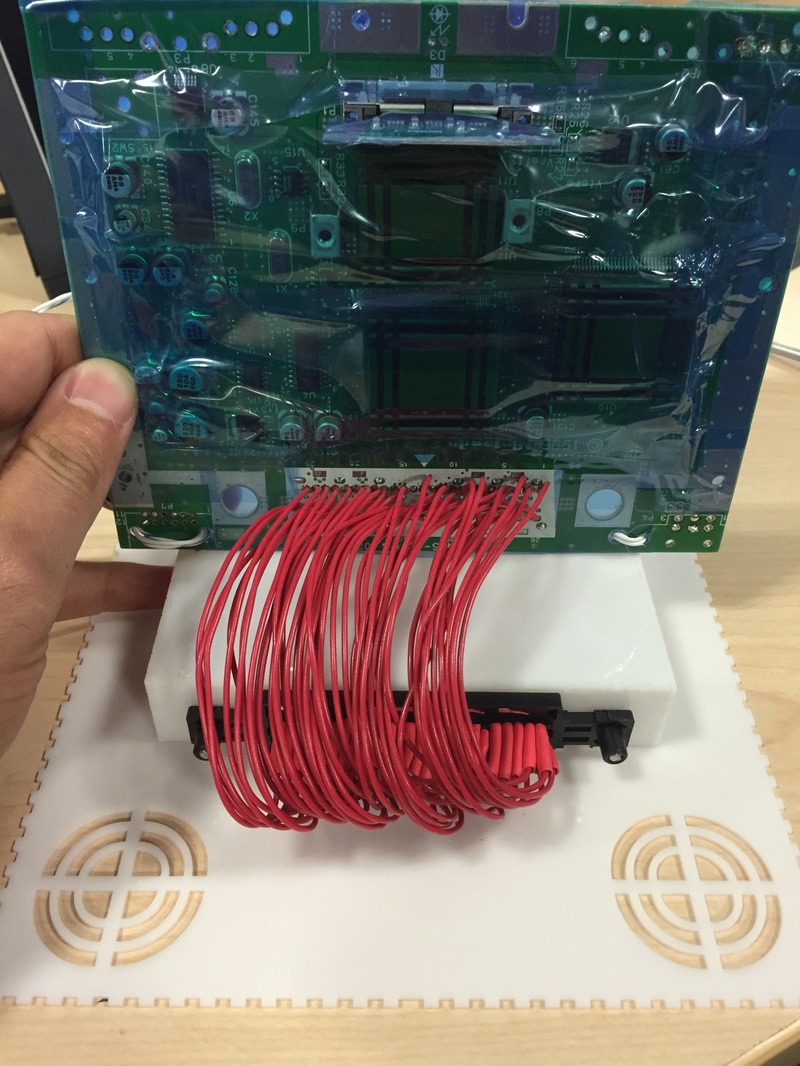
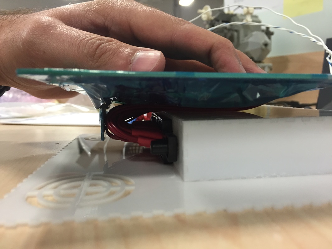
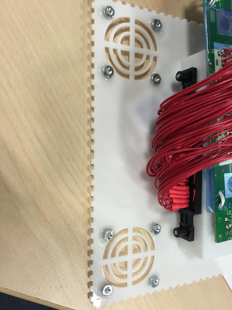
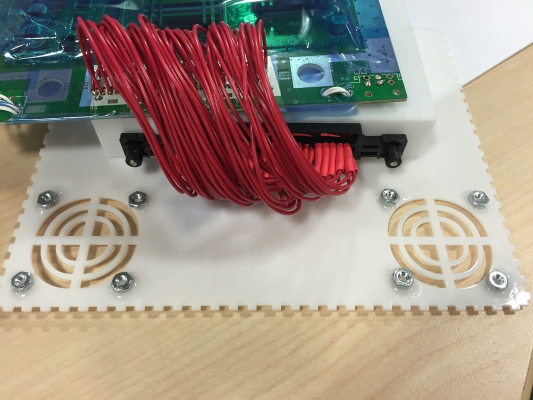
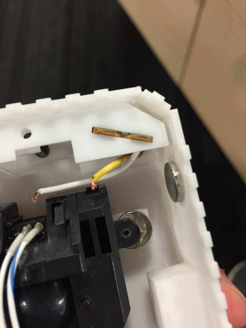
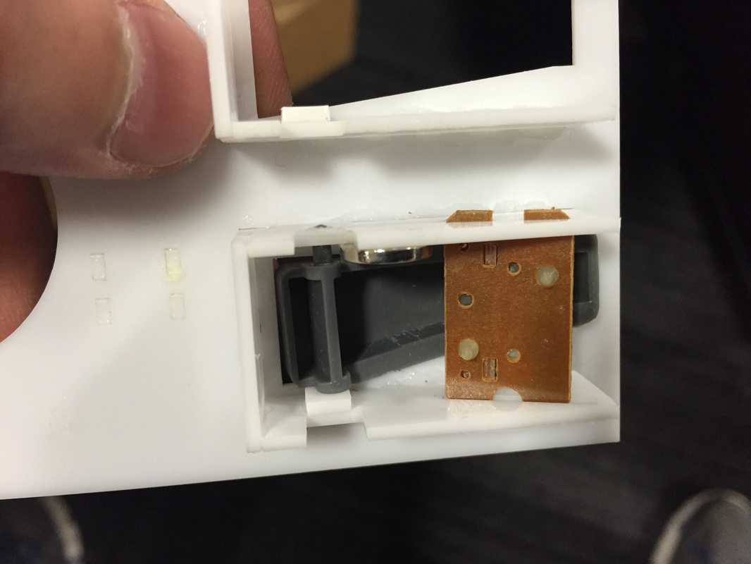
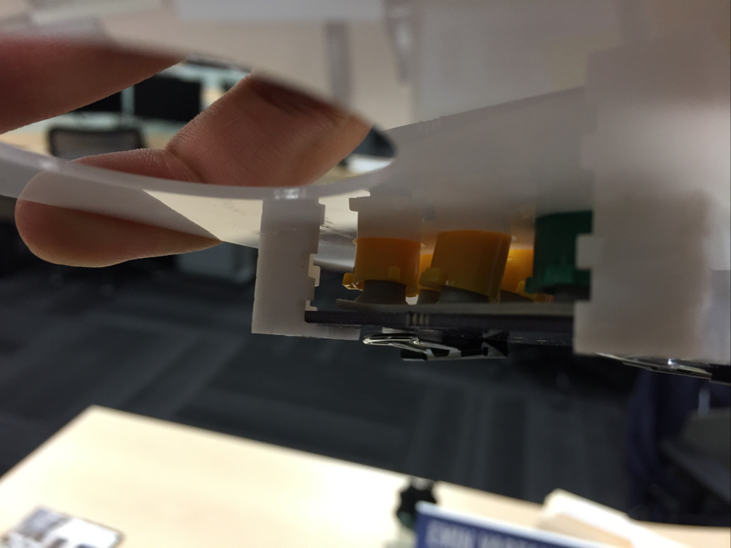
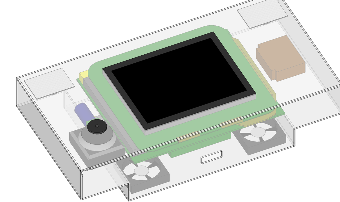
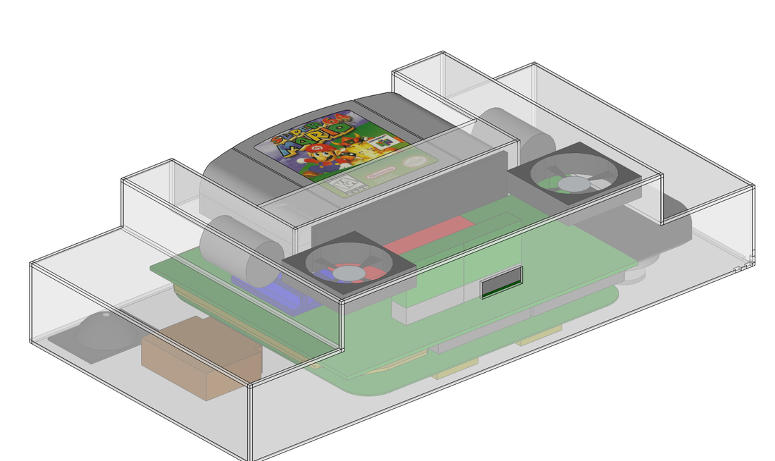
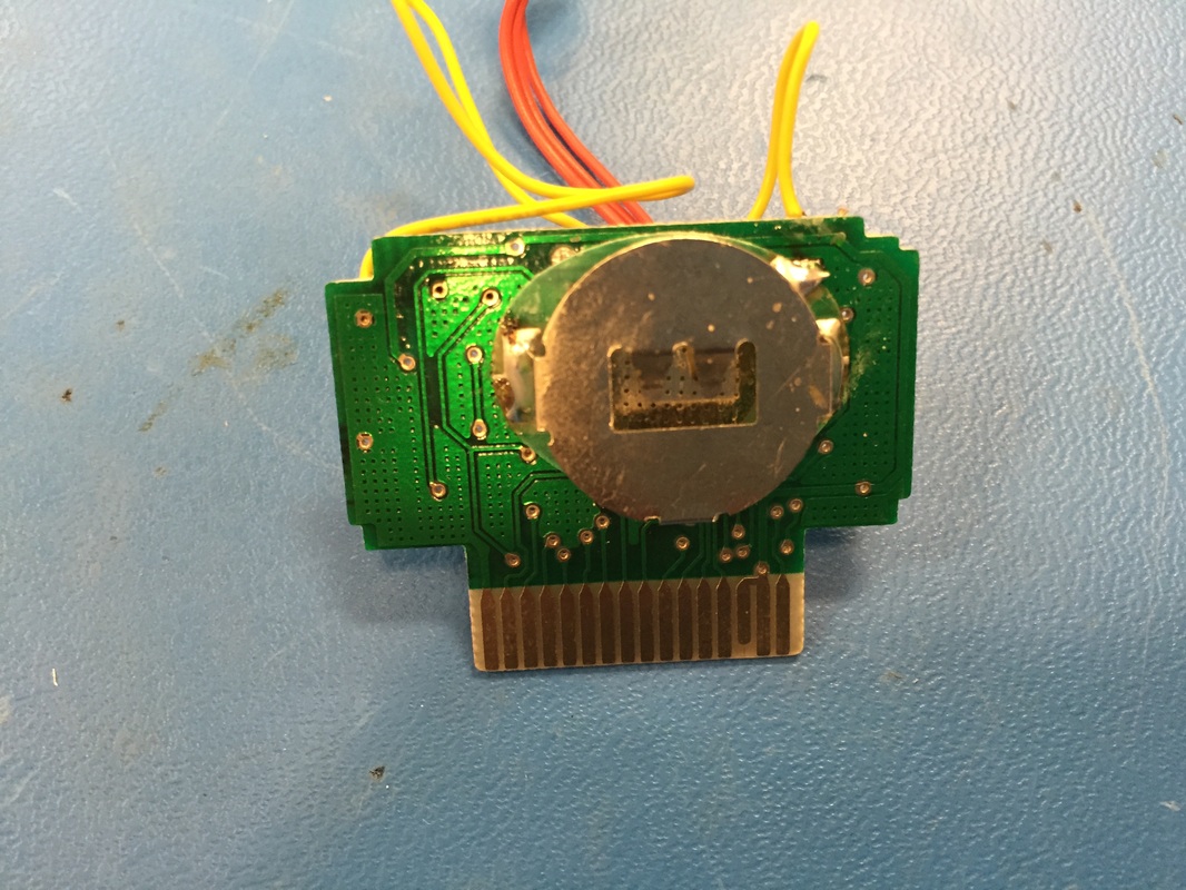
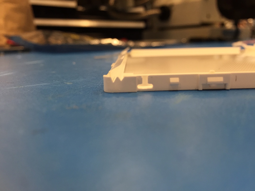
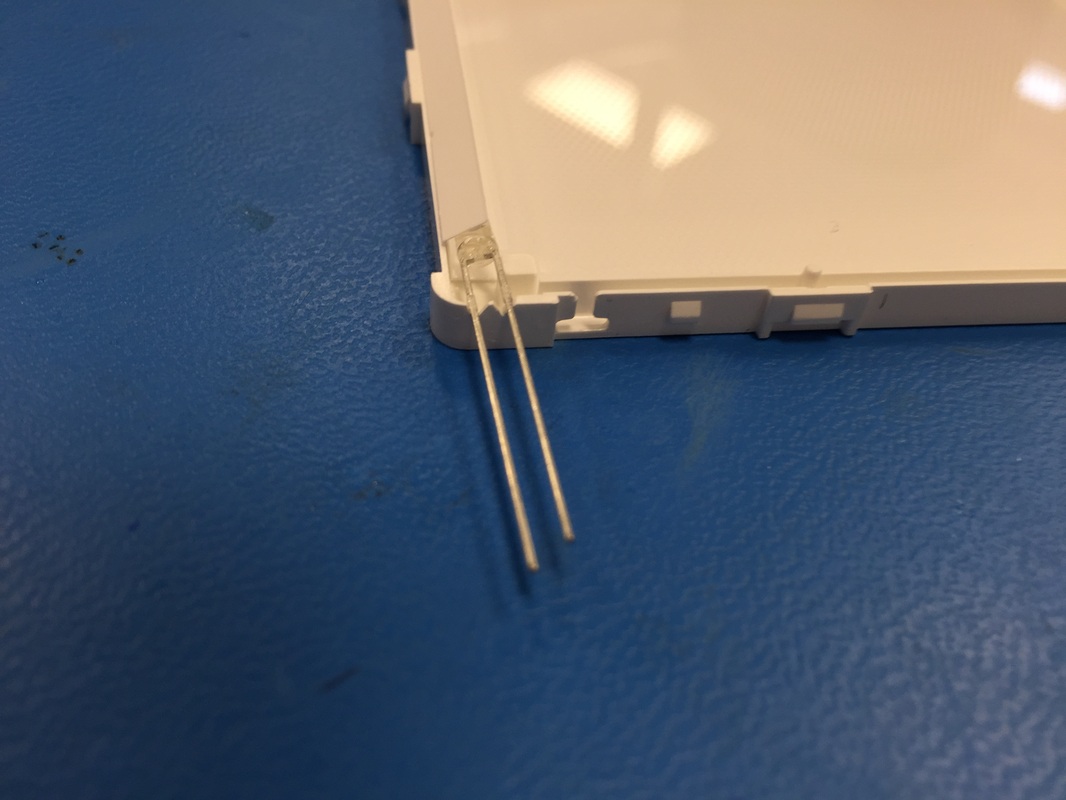
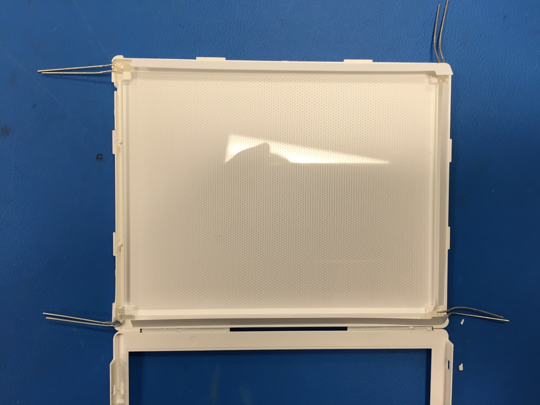
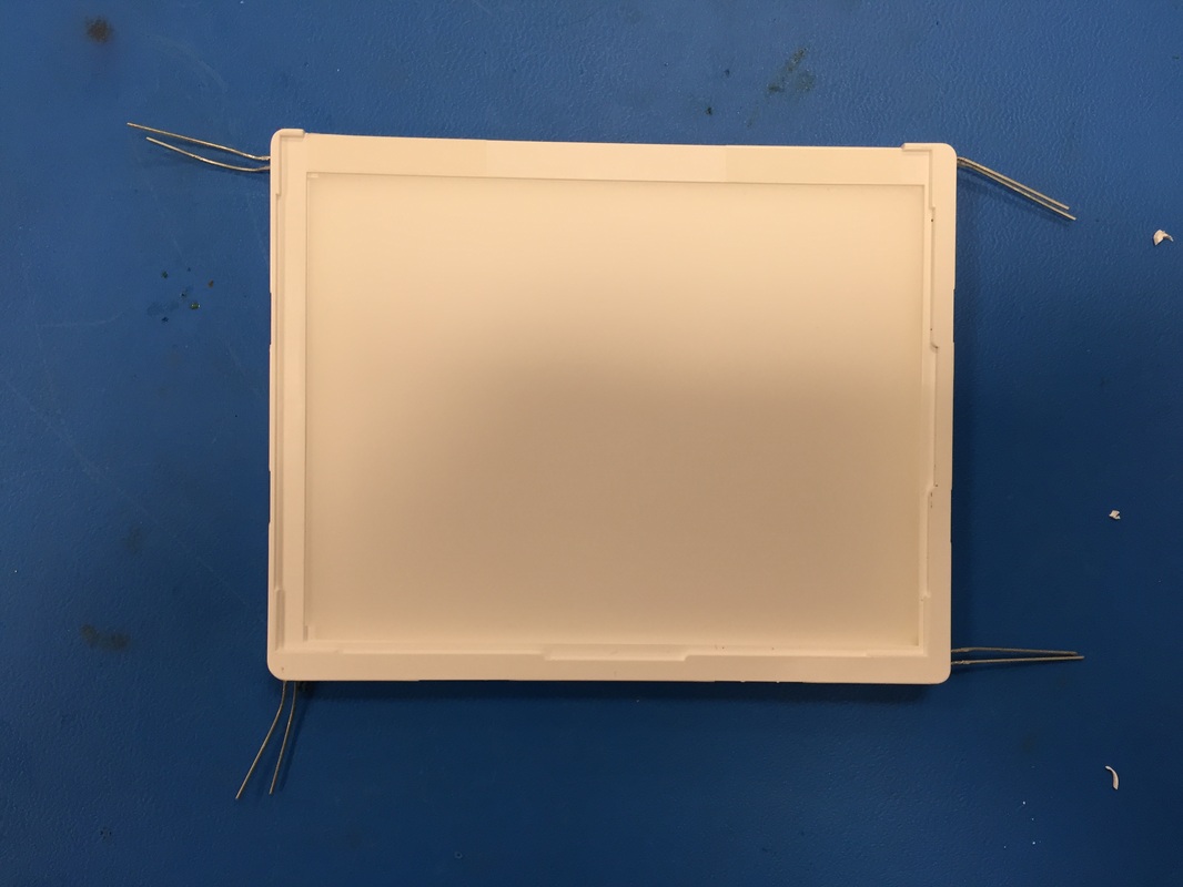
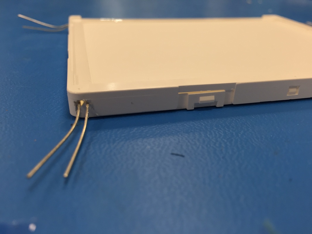
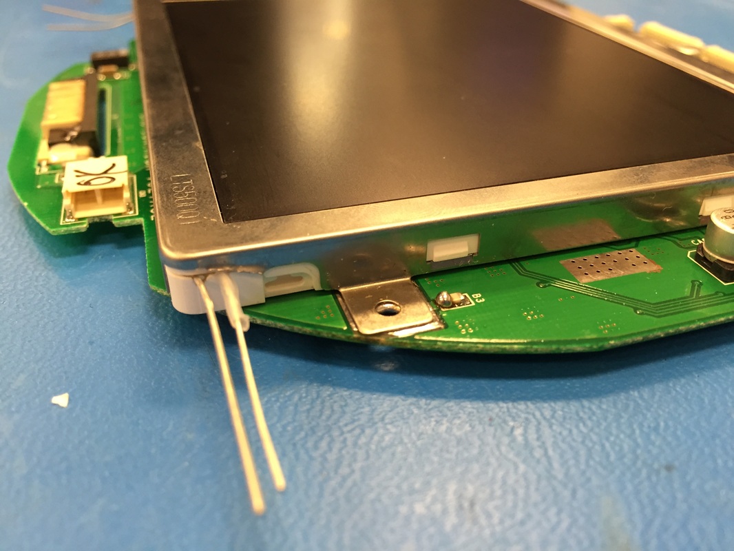
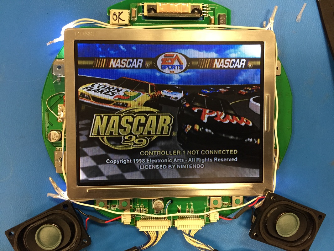
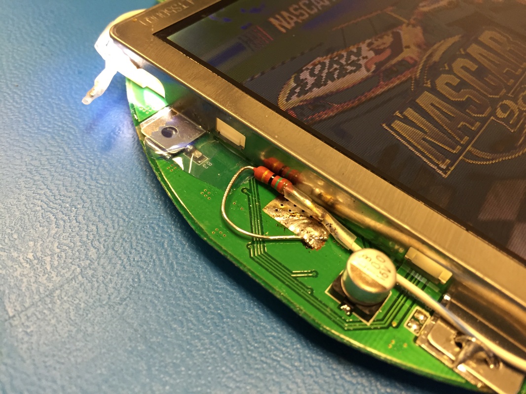
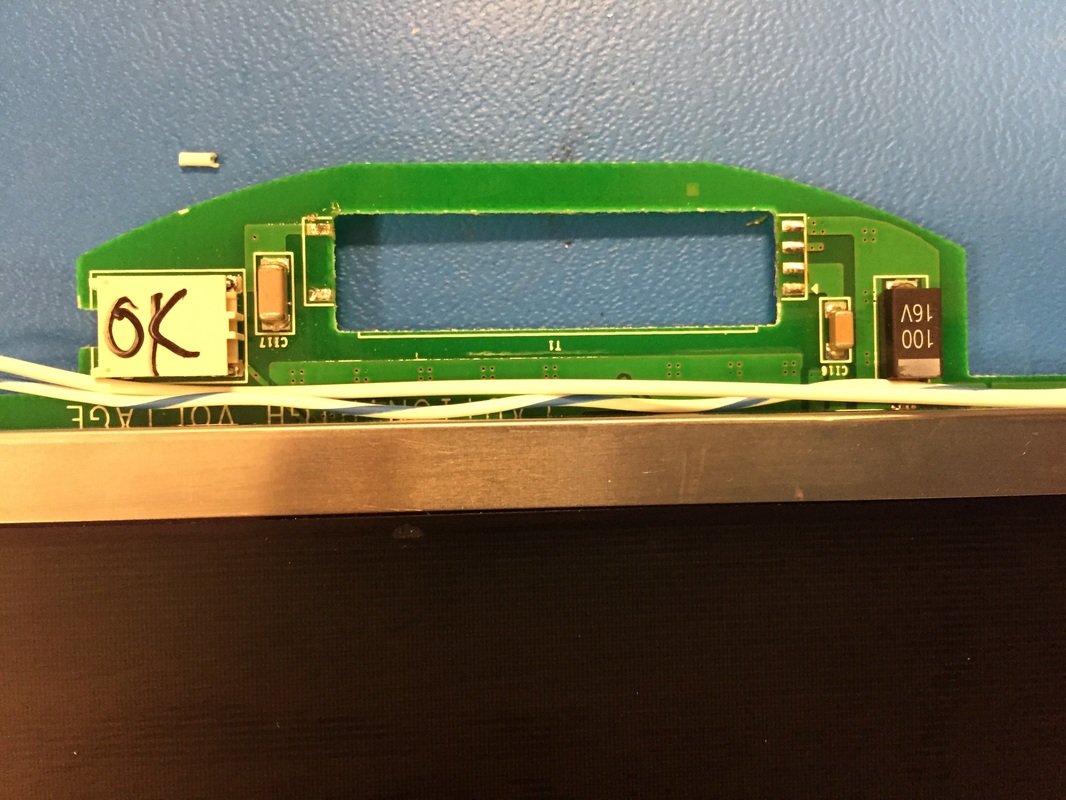
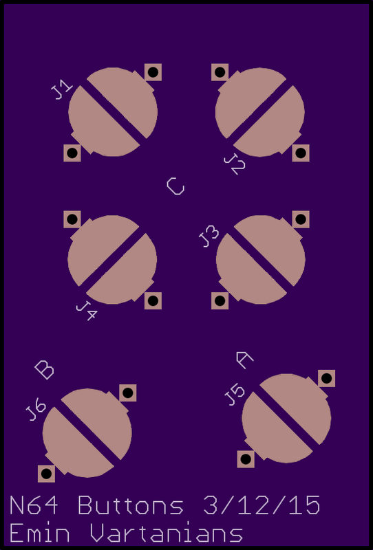
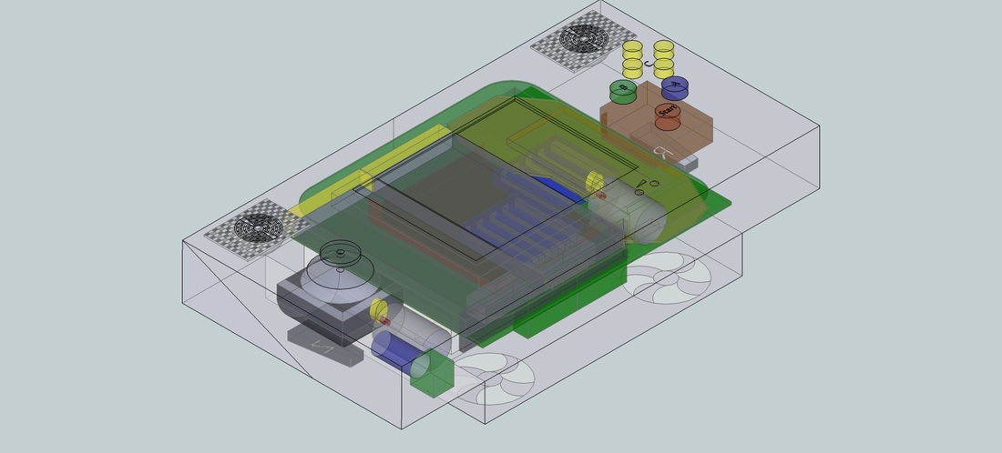
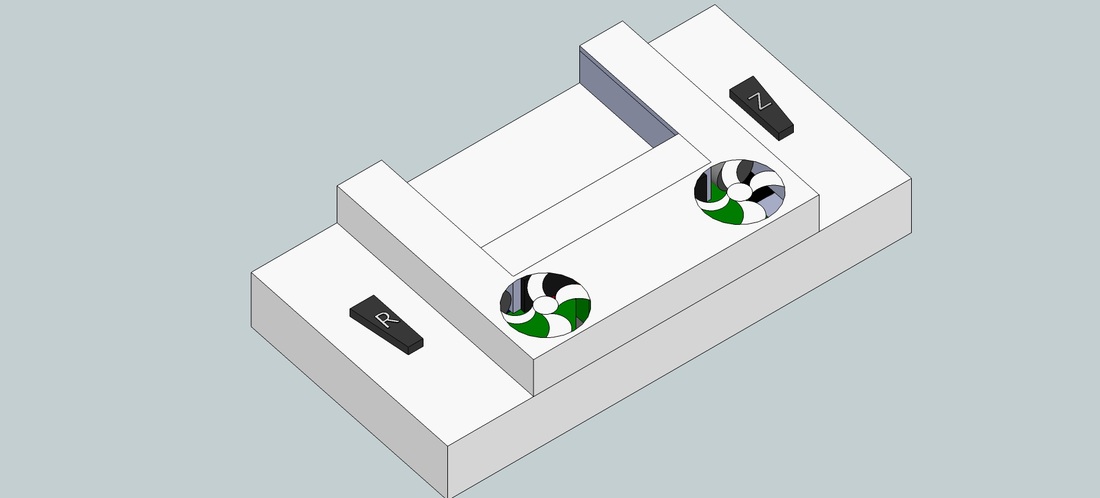
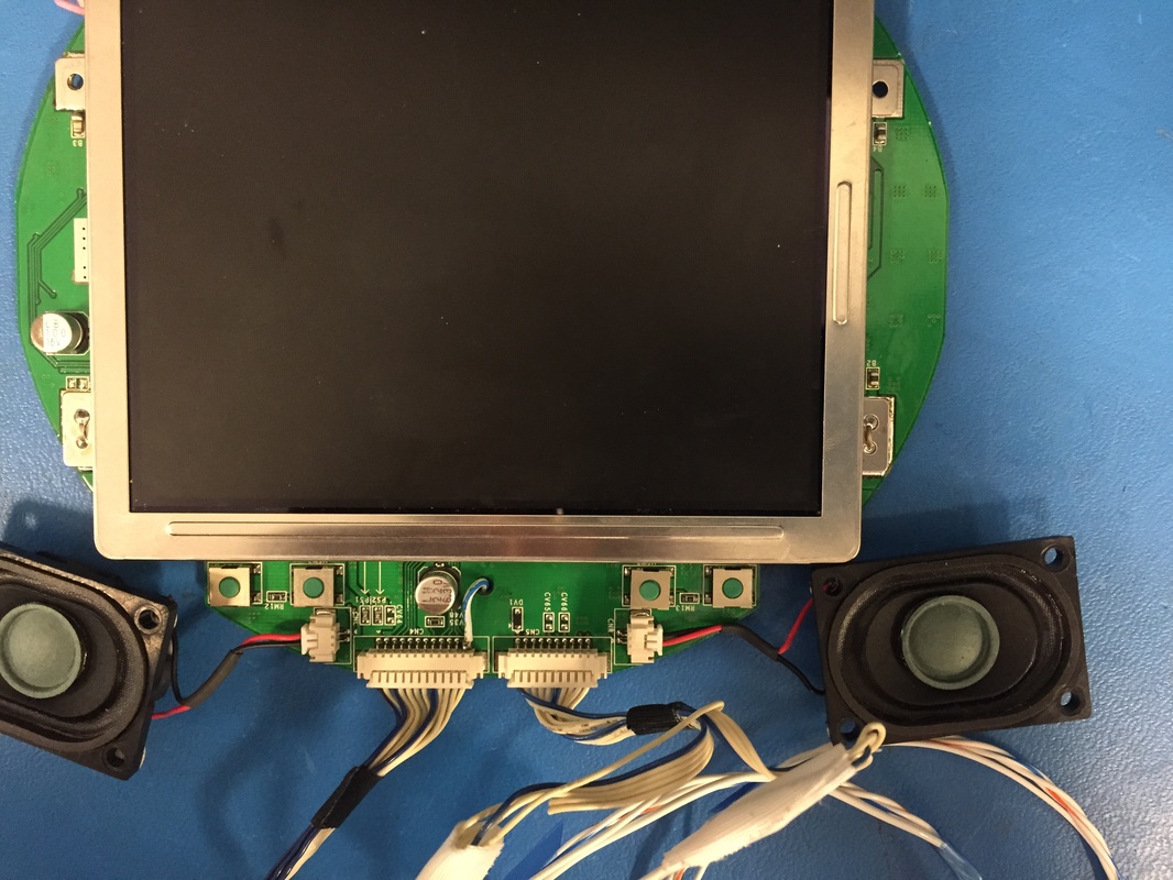
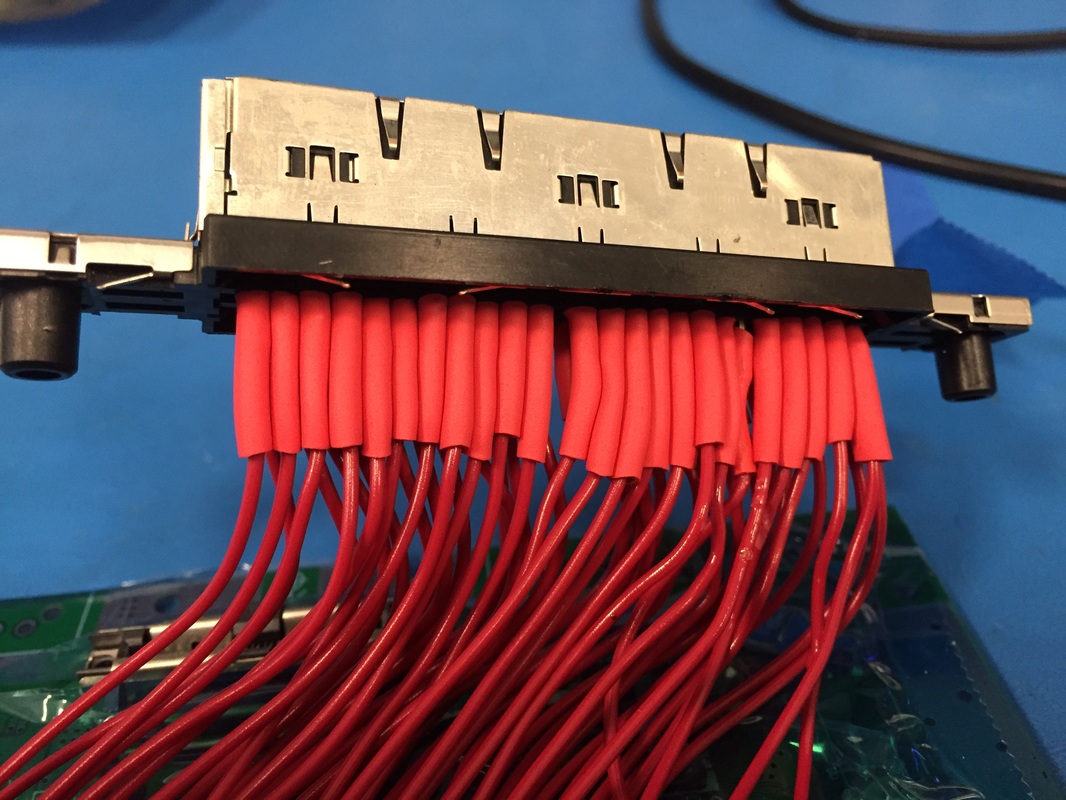
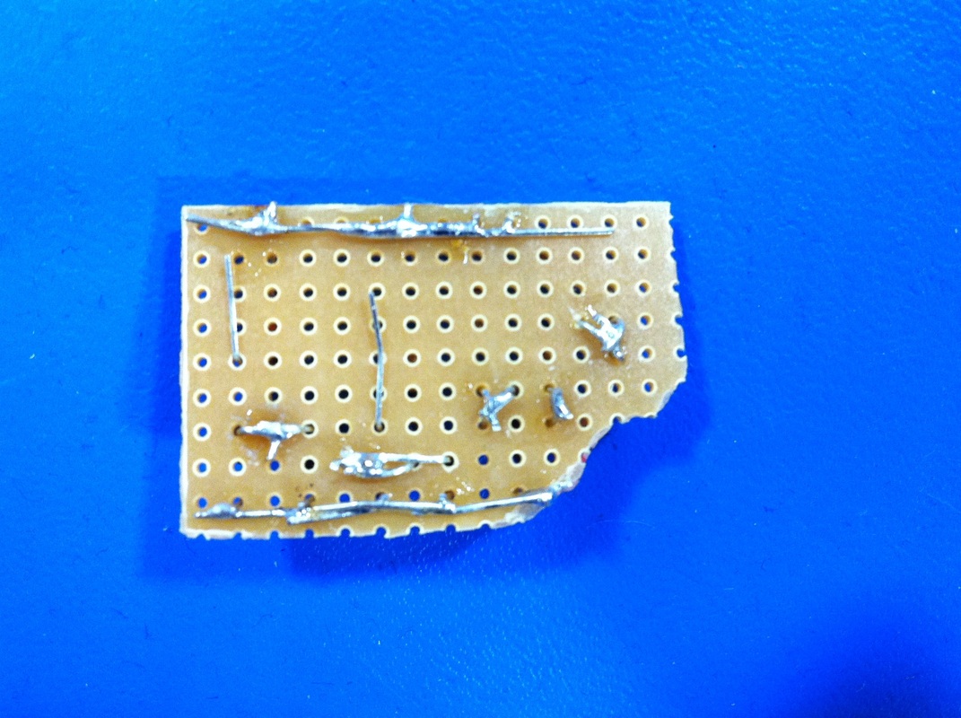
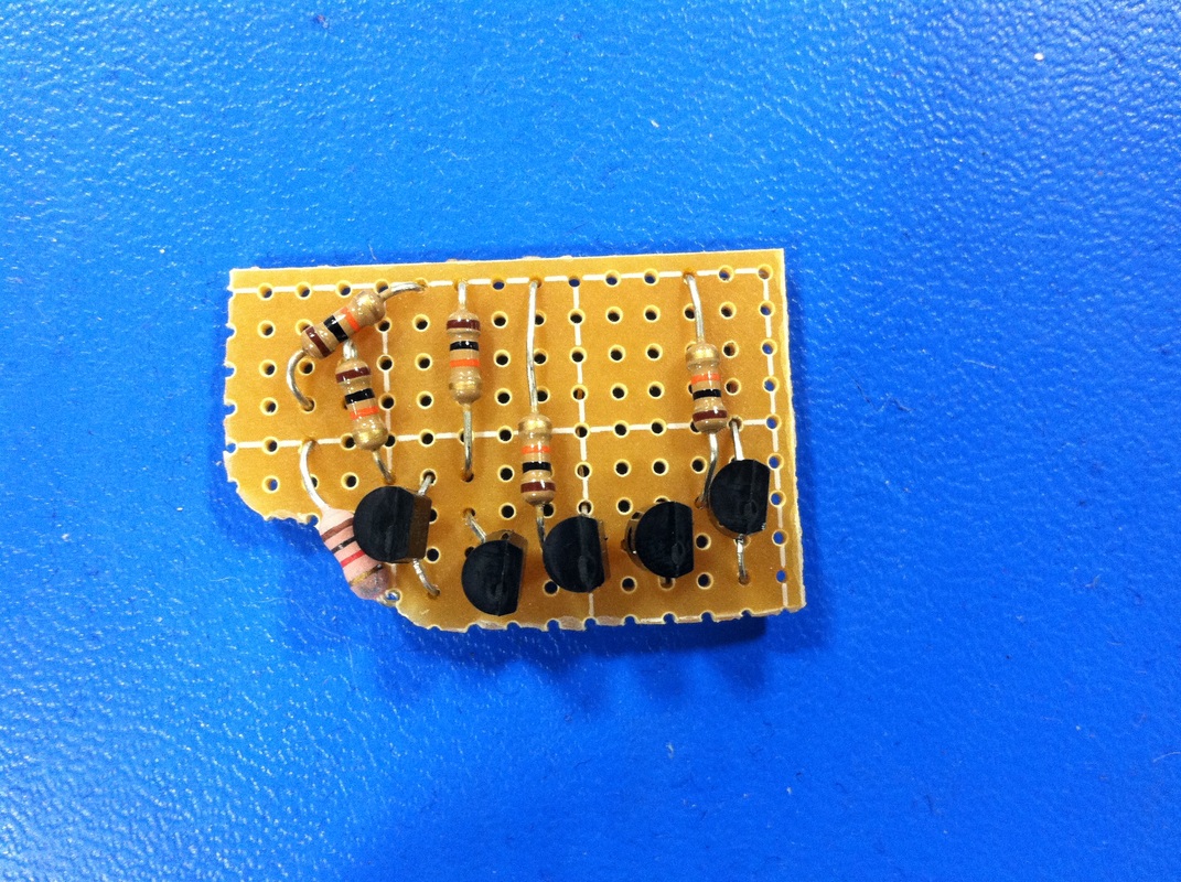
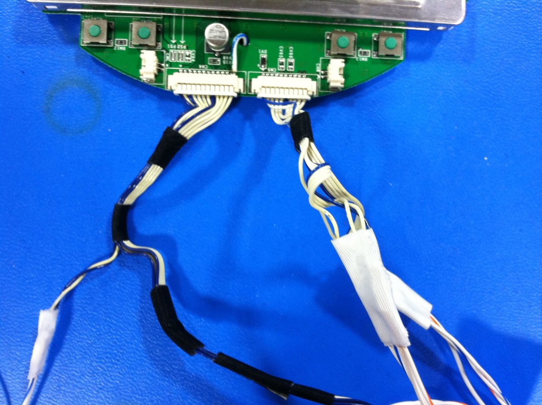
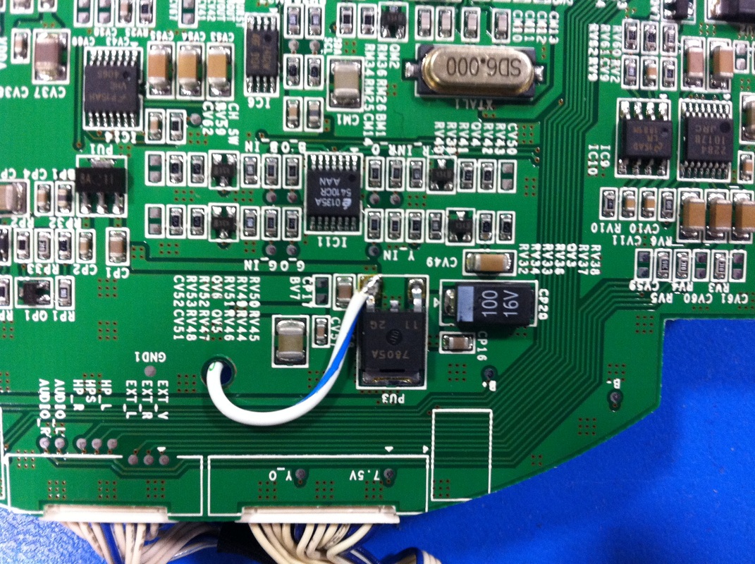
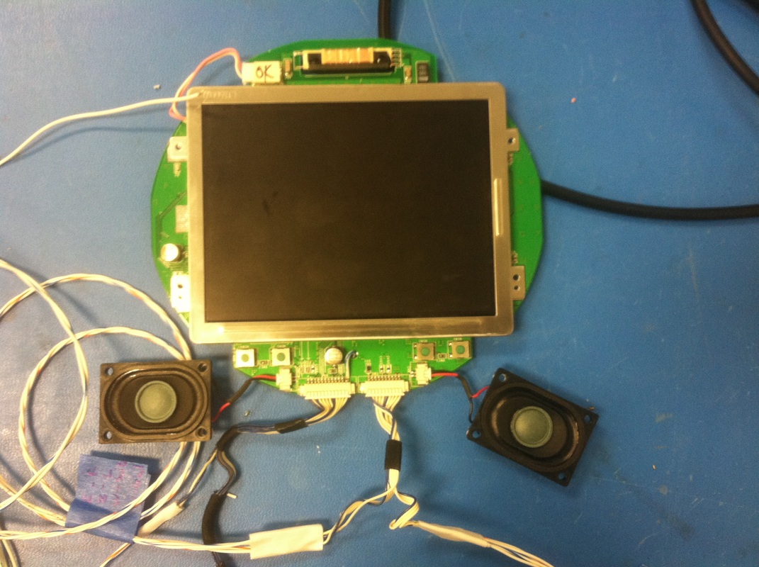
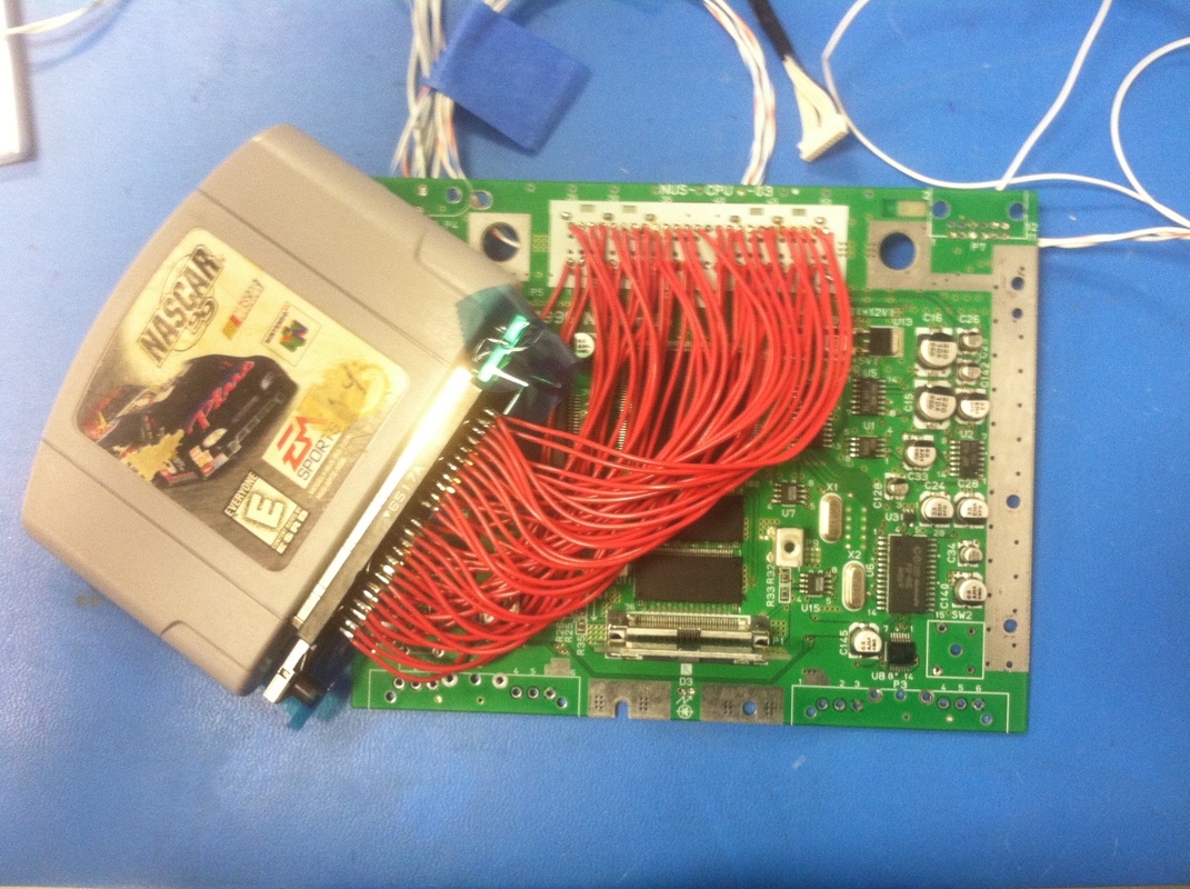
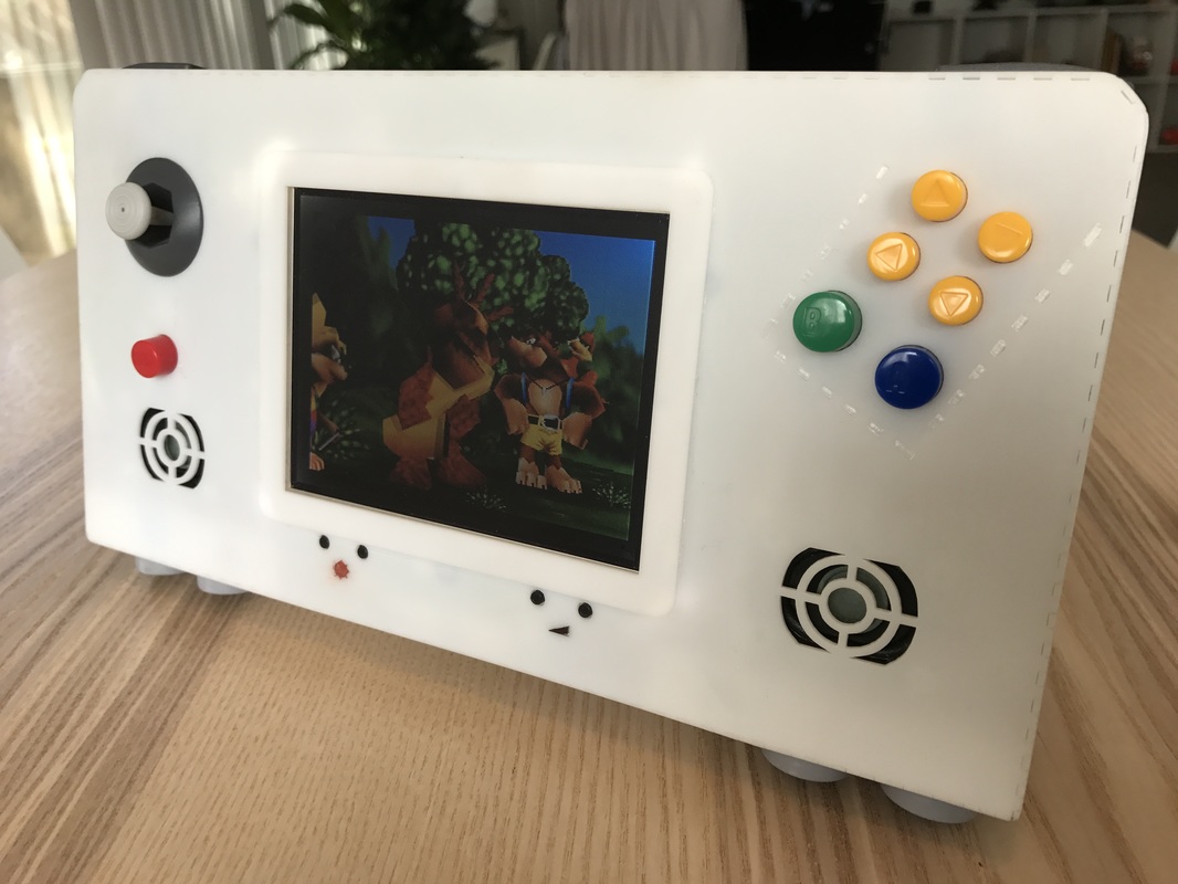
 The Case Cut out the case just like before. Glued it together with minimal problems. Applied acrylic paint just like before, then sanded the puppy down with 80 grit to take off the glue marks and round the corners/edges, 220 grit to take off the 80 grit's marks, and finally a wet 800 grit to get it back to the smooth baby's bottom it started out at. Finished off the case by gluing the nuts in place per before. Had a mistake while sanding the bottom piece where I cracked the plate, but unless you're looking for it you can't really see it. Buttons The ABC buttons were not doing well, the wires kept breaking off the PCB due to sharp corner bends I was doing. So I used the same red wire as way before when I did the cartridge relocation to do the ABC buttons. Also taped them down for strain relief and we're good to go. Main PCB I realized I hadn't taken a good picture of the bottom of the main PCB so here you go. Also put solder on the legs of the battery indicator button to strengthen it against the user pushing. Face Plate Started assembling the face plate just like before. The ABC buttons fit really easily since the rewiring. The screen screw hole locations were still a bit rough but I'm glad they worked out and held. I used a screwdriver threaded through the hole to make a small mark on the acrylic so I knew where to glue to screw. Integration This was strenuous. Lots of small details you can probably see better than me explaining in words. I rewired almost everything with 26AWG silicone wire since it was better for the tight curves, The integration sequence is pretty particular, the order really matters. The controller PCB bends a bit as you can see since I didn't size the N64 board's component heights very well, but since the controller PCB is so thin I thin and has copper only on one side I think it'll be fine. I used lacing cord to bundle all the wires together for neatness, used a clove hitch knot followed by a regular knot (half knot) to secure all of them. Final Product Here is the final product! the face plate fits perfectly on and is not being pushed up by the wiring inside like the test build before. The rumble motors work beautifully, the screen is a little dark under the sun but it'll do ok. All in all I'm really excited about this project. I'll do a demo video soon showing off all its features. Thanks for following this thread, half the fun has been seeing what other people think of the project so don't be shy about commenting.
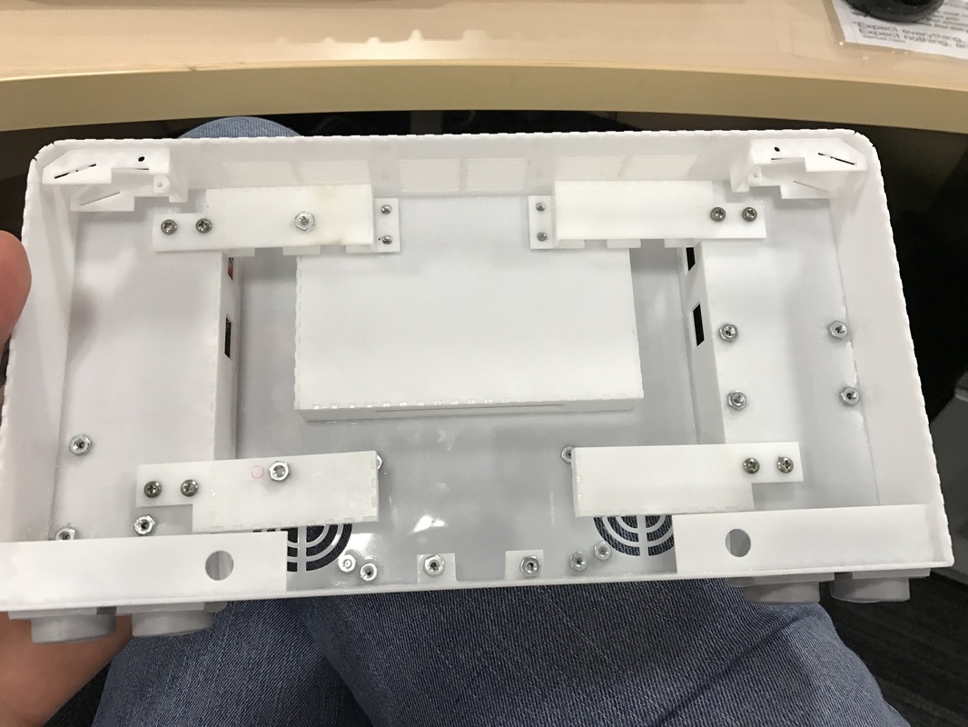
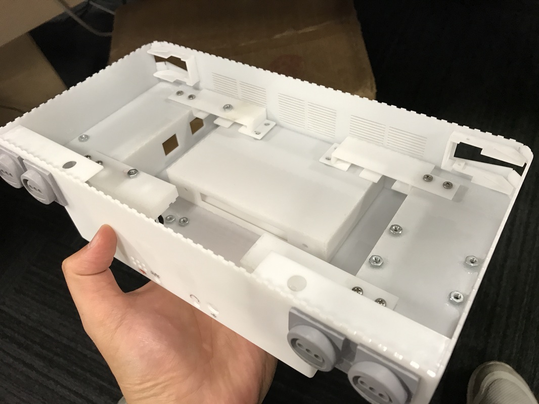
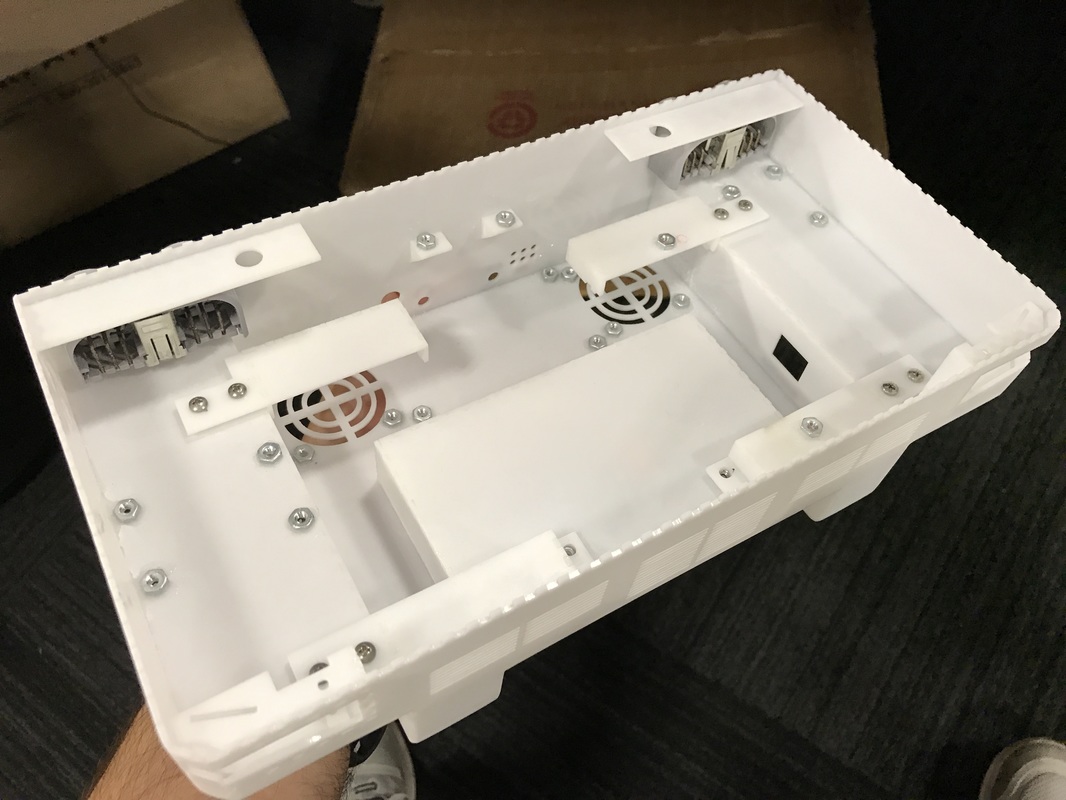
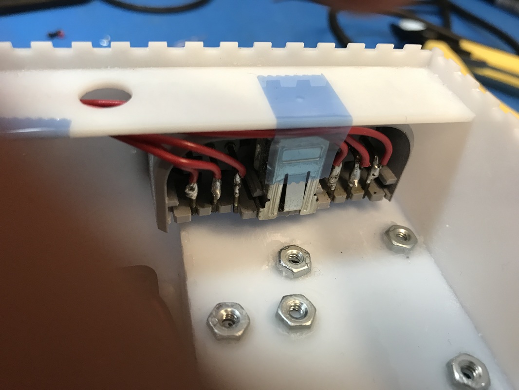
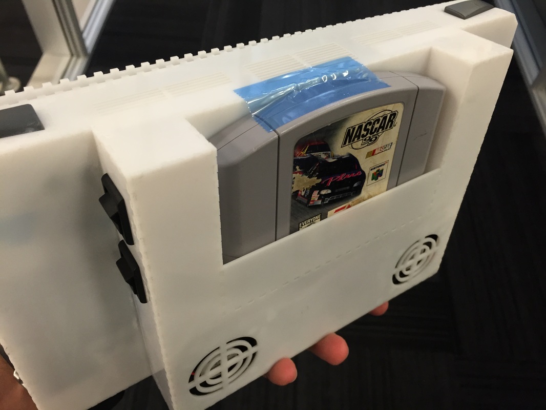
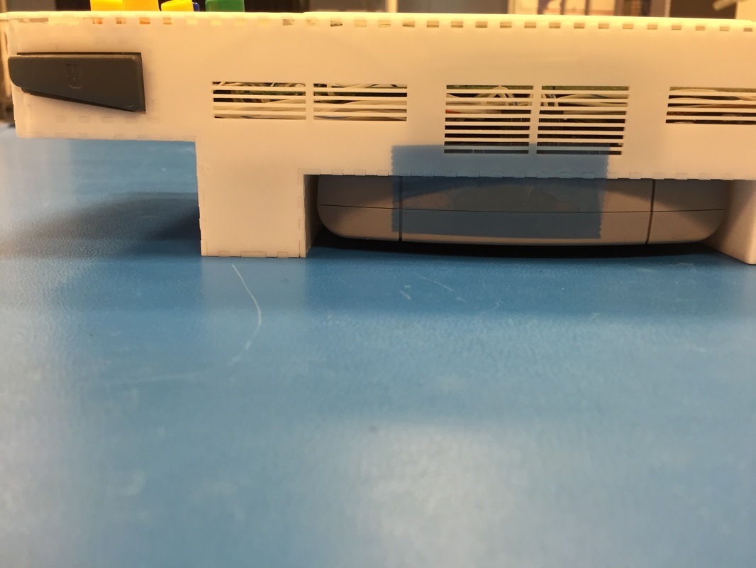
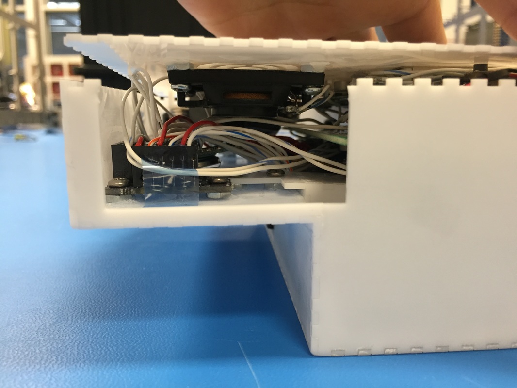
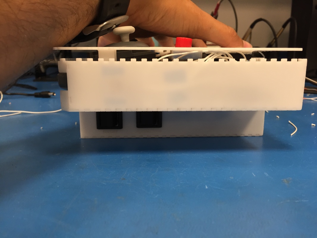
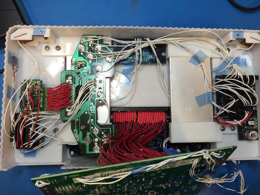
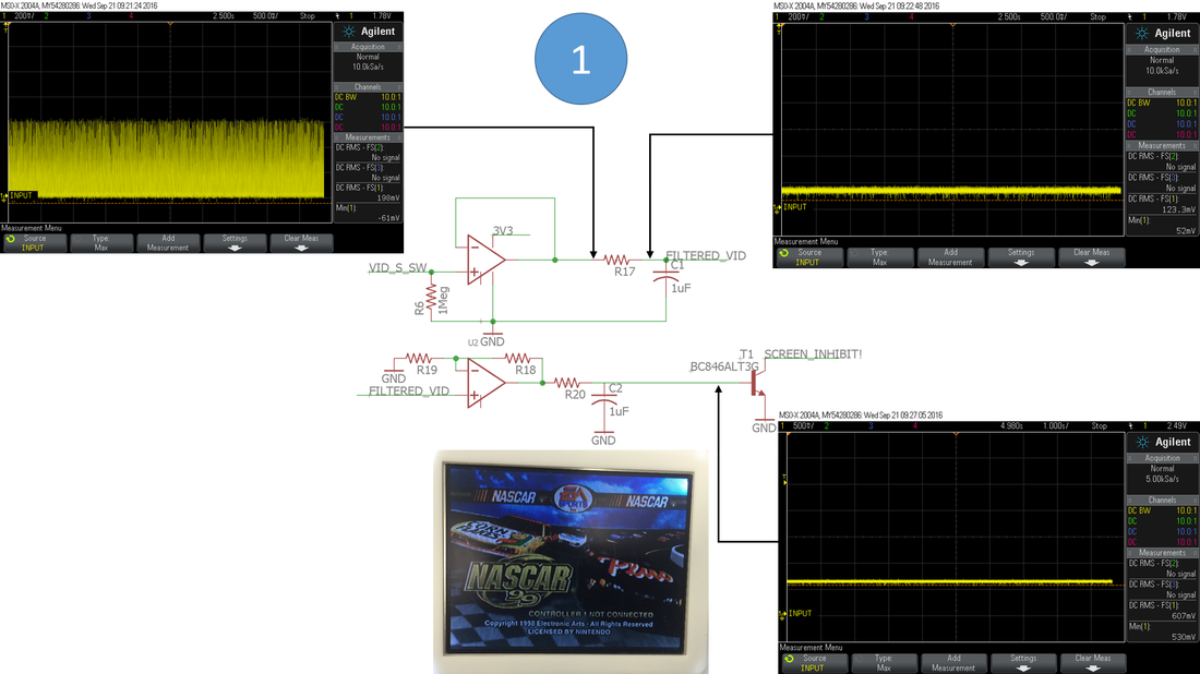
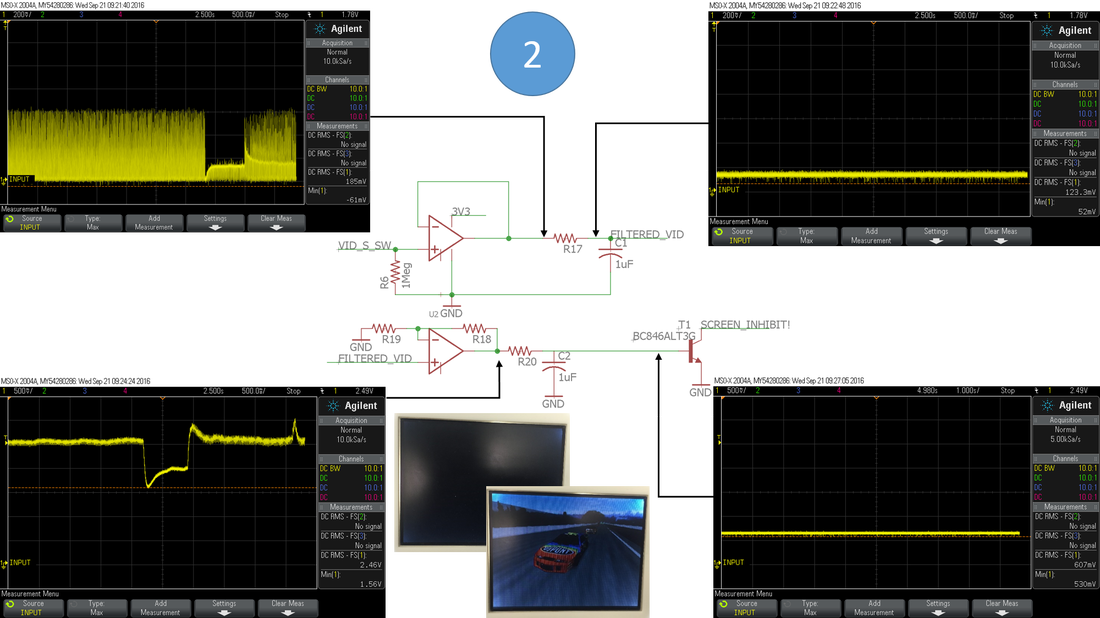
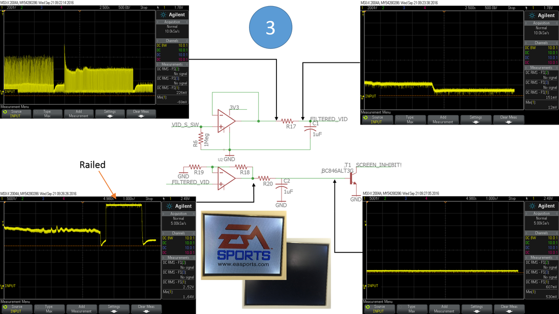
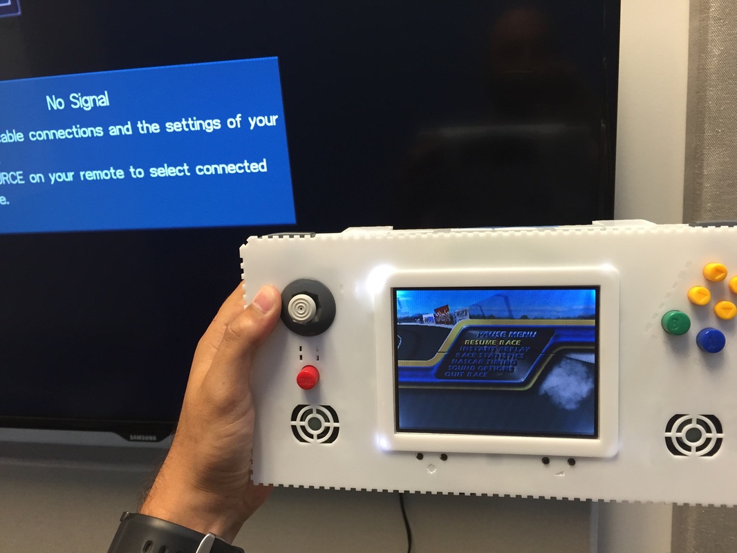
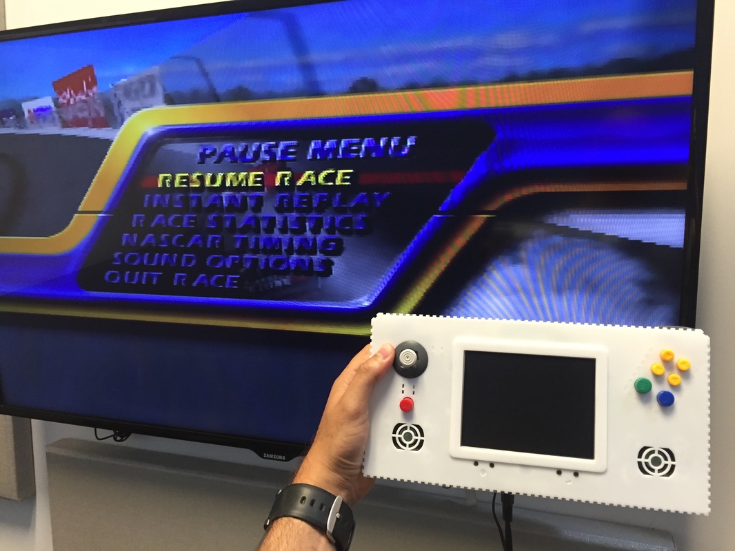
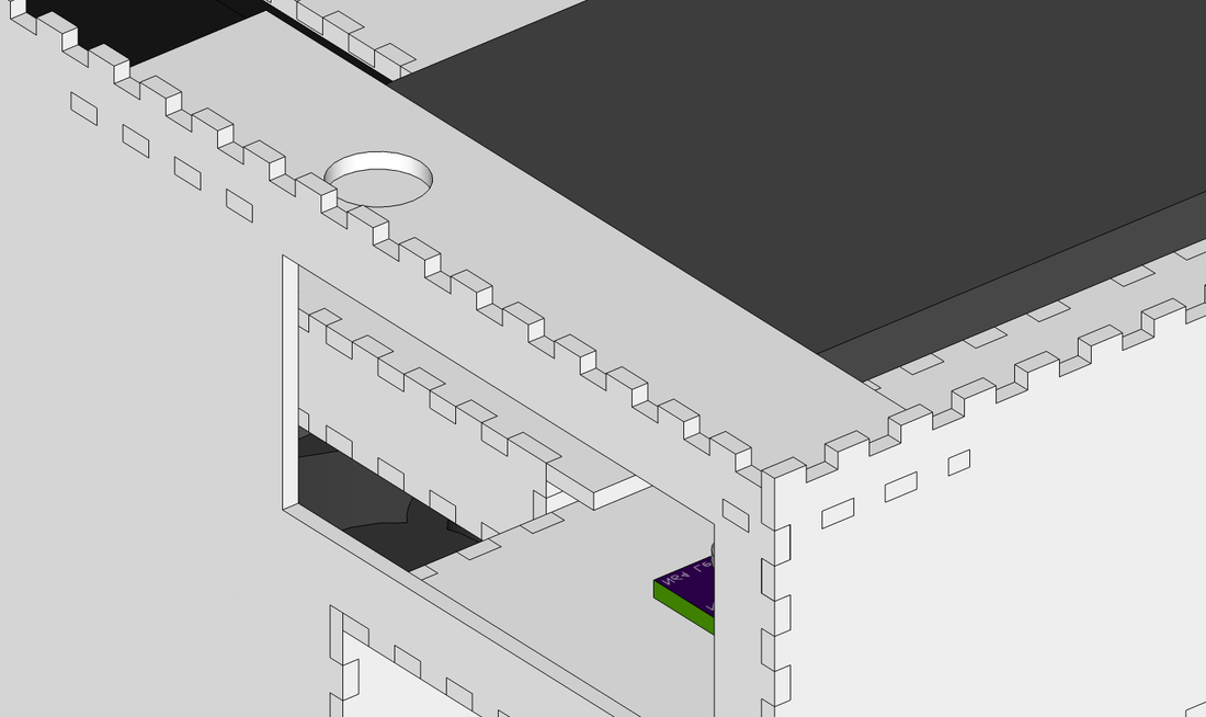
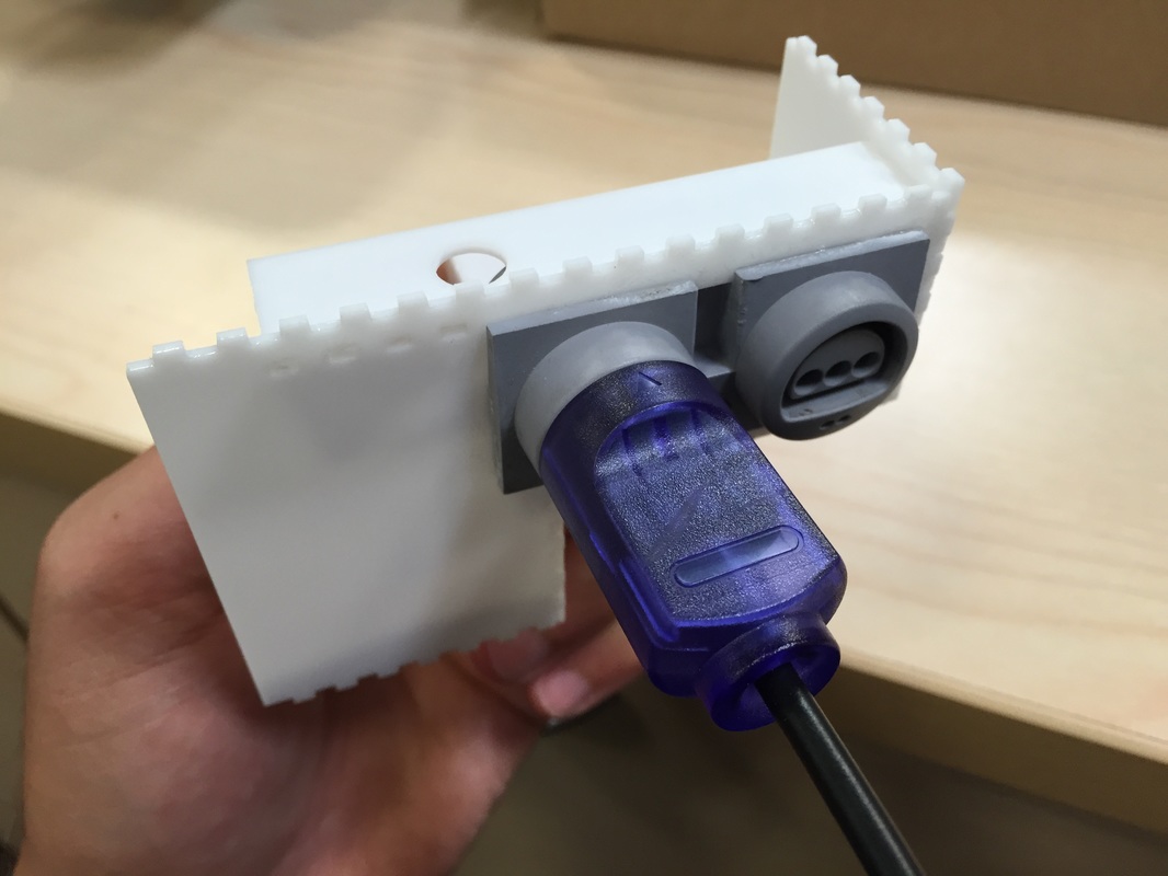
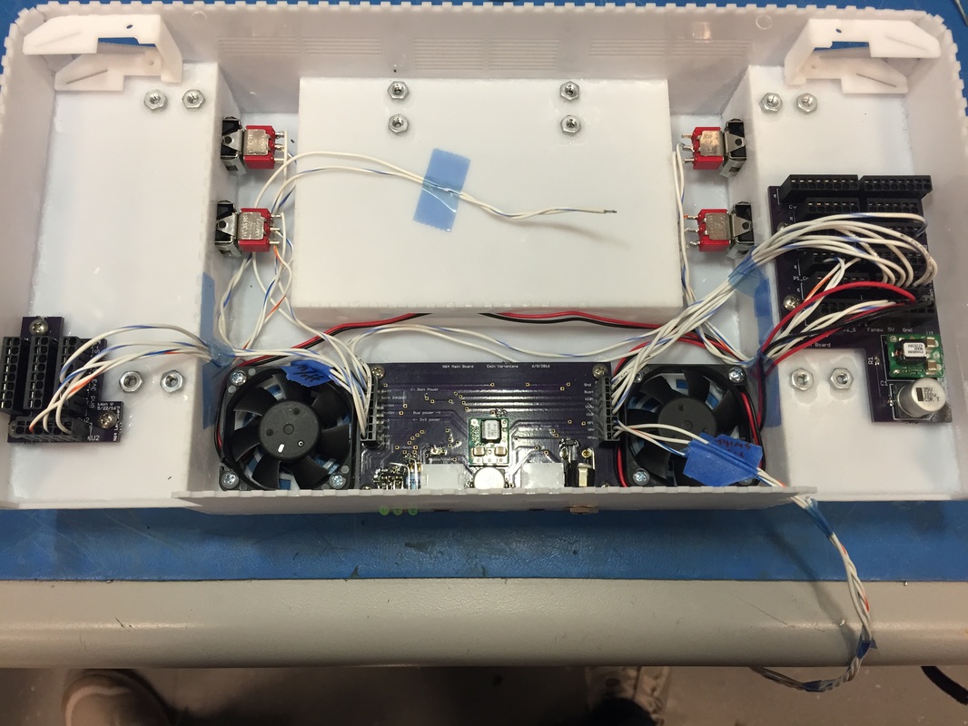
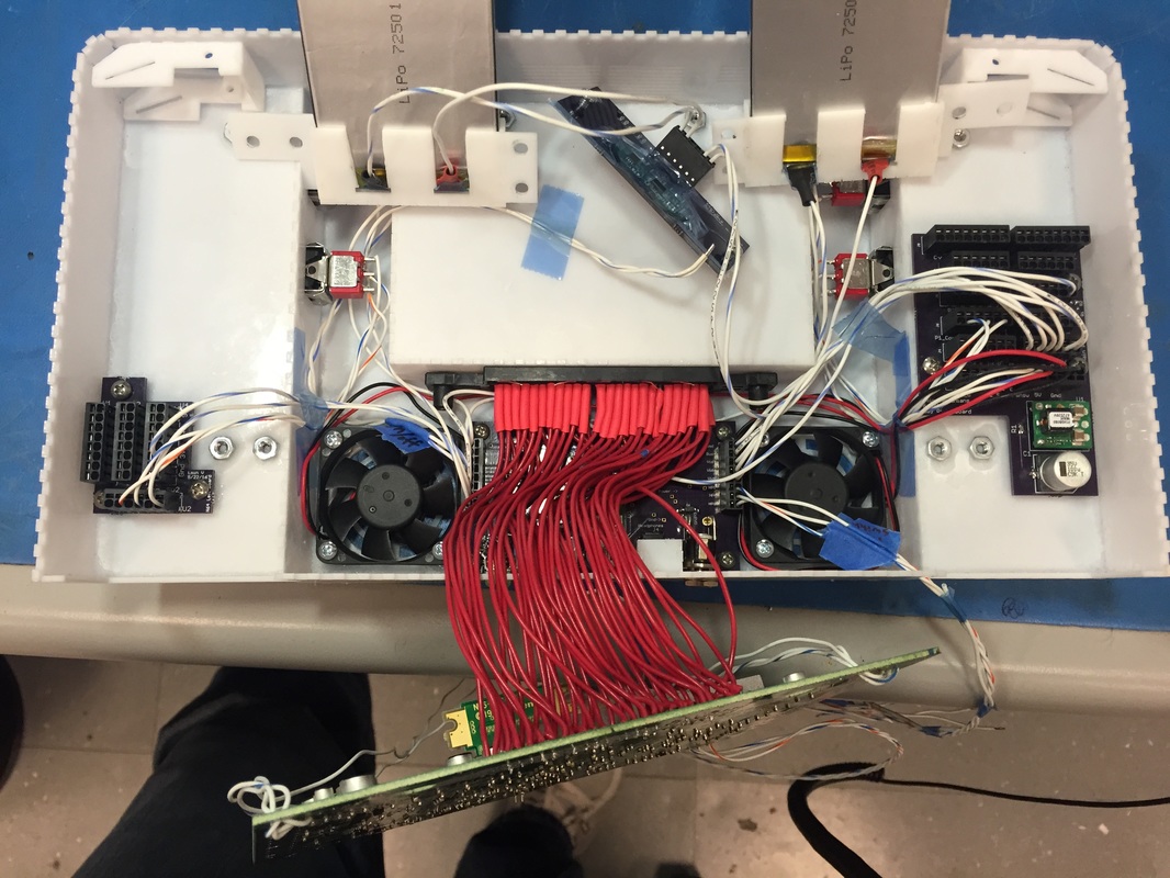
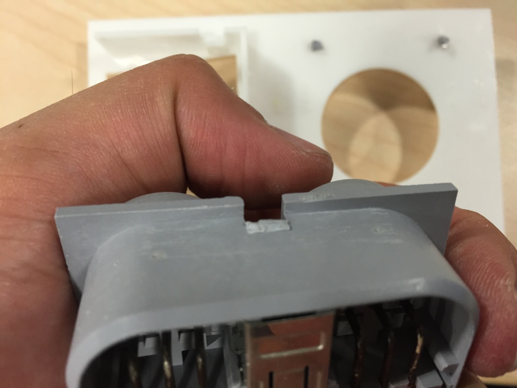
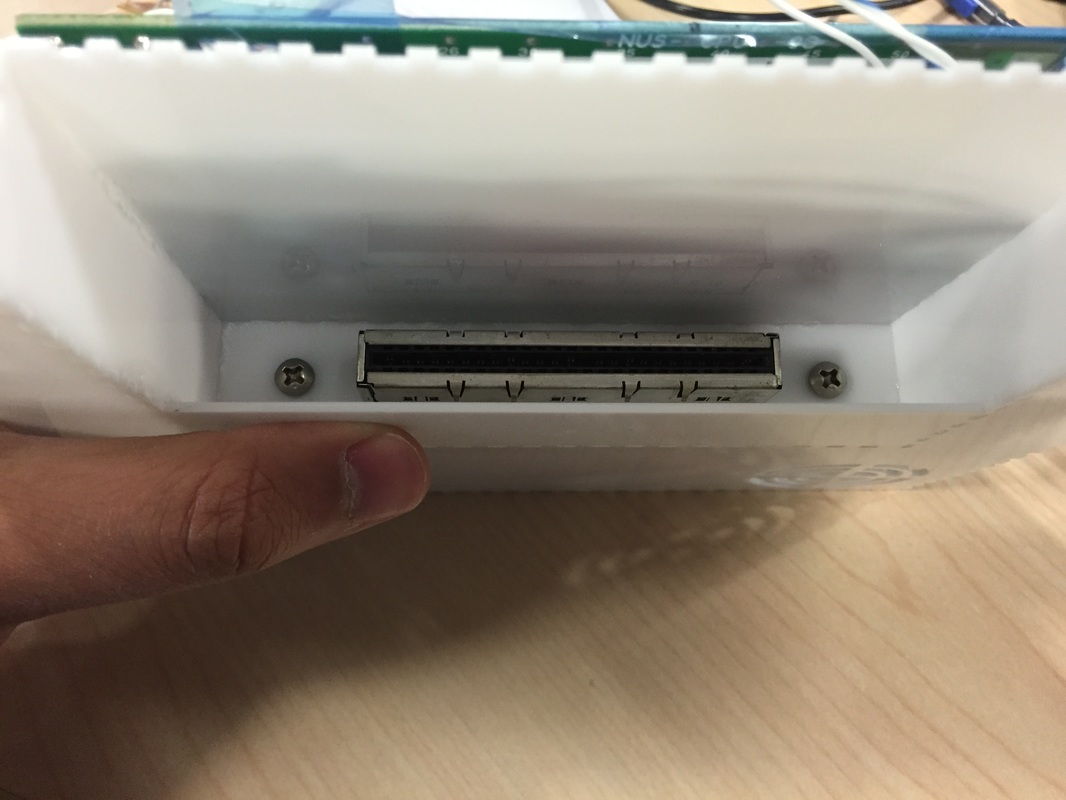
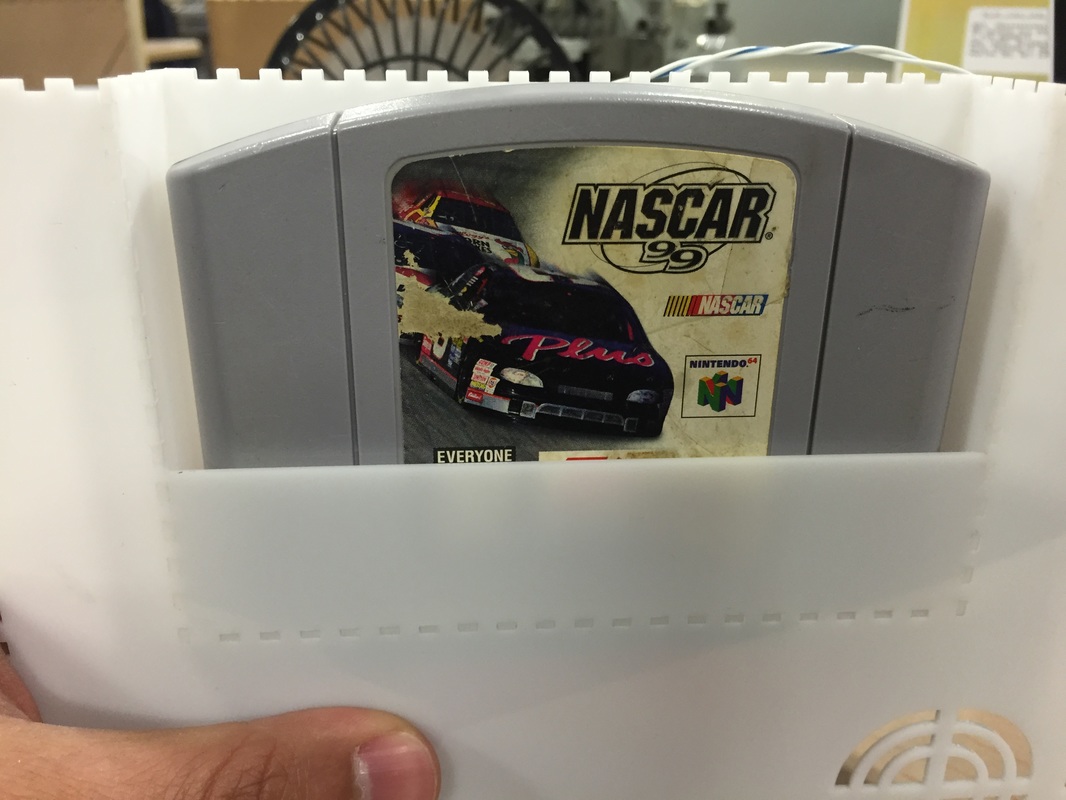
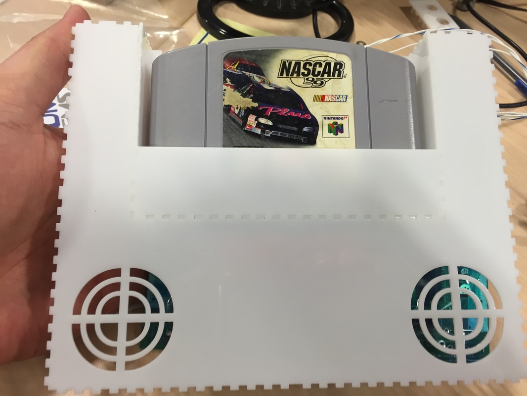
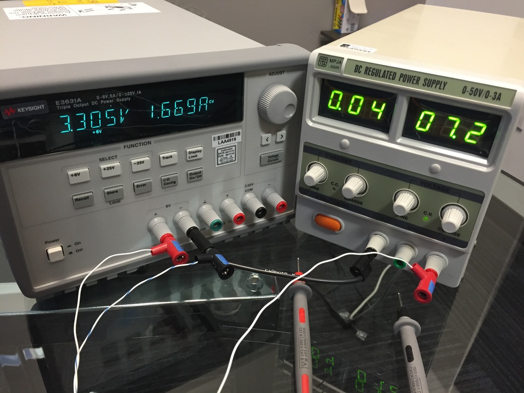
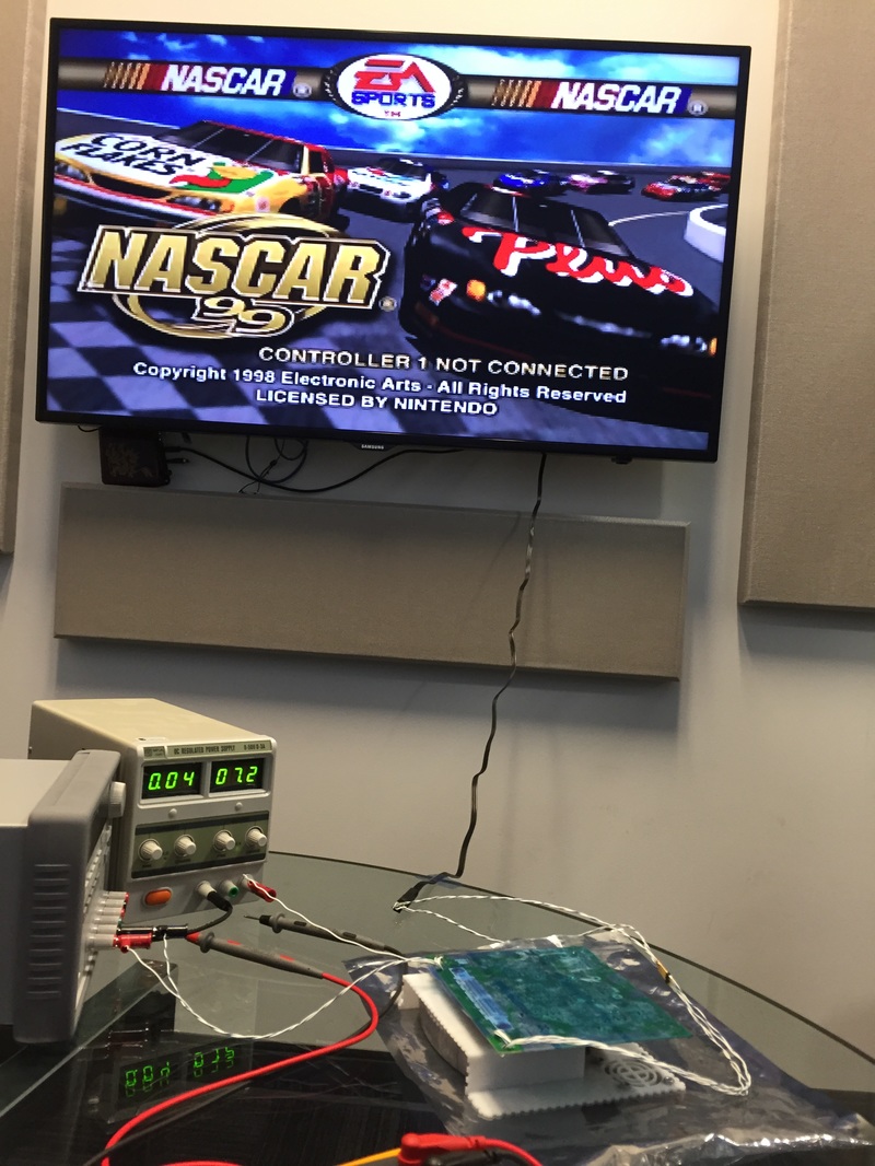
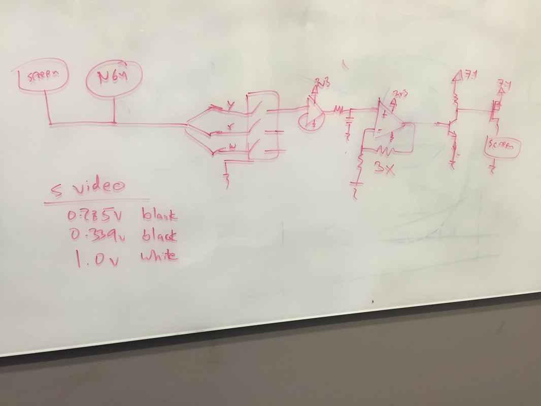
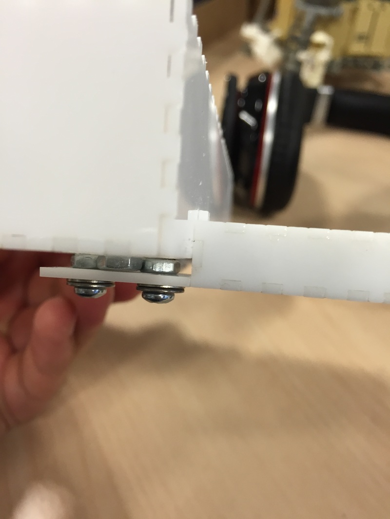
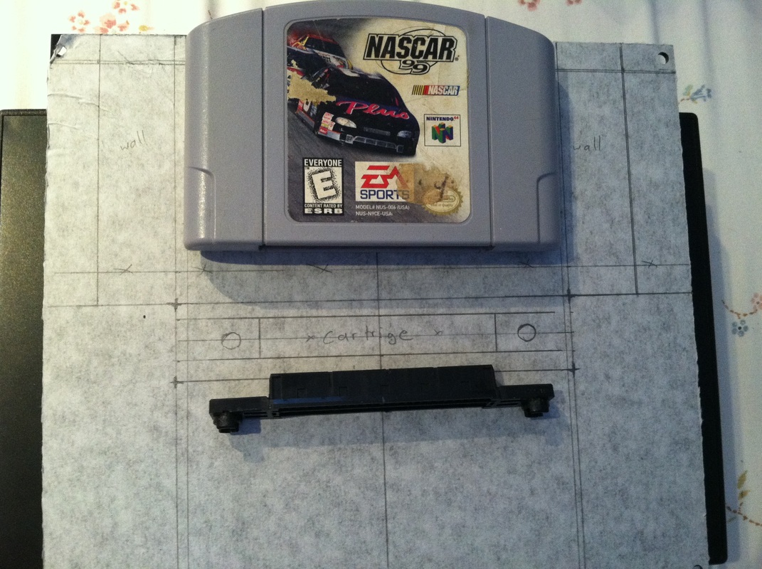
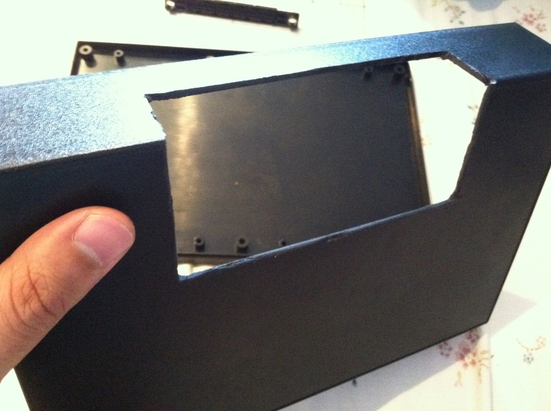
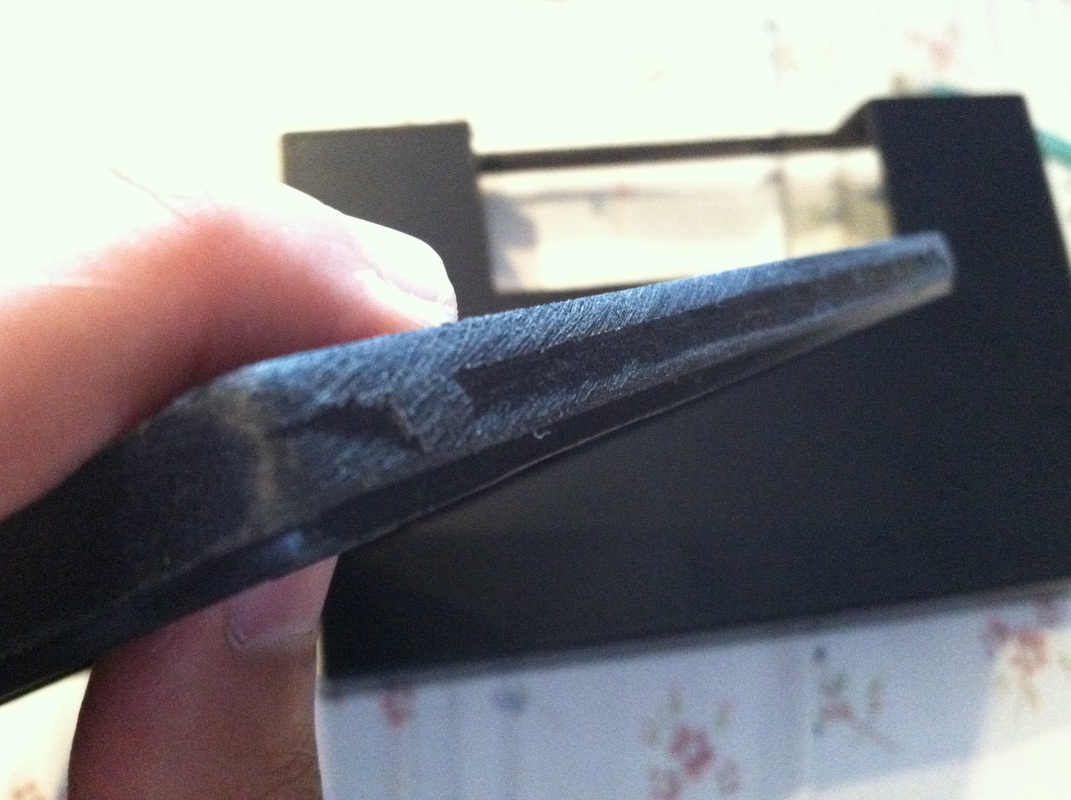
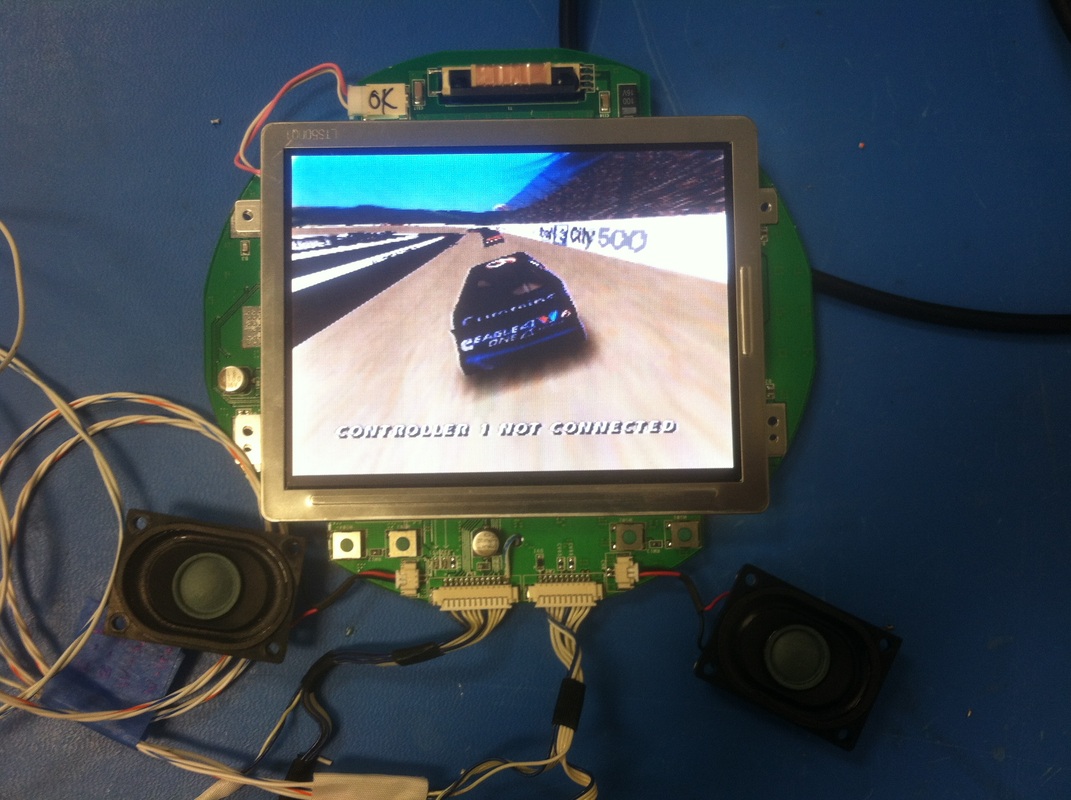
Integration I assembled all the pieces in and did a full account of all the small changes that need to be made before the final pieces can be cut. I think after this blog post it will be time to cut some final pieces and start gluing and sanding the box,So as I integrated stuff into the box I was snipping wires and making the wiring as short as possible to reach the terminals.After a ton of soldering and cutting I ended up with pretty short wires but they extend too high above the connectors to fit in the box when I bring the cover down. You can see in some pictures that the speakers are hitting the wires and not allowing the lid to close.I measured the distance to be about 6mm to I gotta make the top part of the case higher by 6mm, not a huge deal. I also found out that I gave too much margin to the cartridge so if the game isn't buttressed it'll fall out, I'm using tape to hold it here but for the final assembly since I don't wanna redesign everything I'm just fitting in small rectangle pieces inside the cavity of the cartridge. A/V Jack Seems like the video detection circuit isn't working too well. It still randomly cuts the screen off when the signal is too low. So I went back to the circuit and R18 from the 9k it was to 19k. Its definitely overkill to amplify the signal x20 but I'd rather overdrive the opamp the few times that the screen is fully white than to under drive it and have the screen turn off randomly. You can actually see in the diagrams below the succession of screens and how the signal looks at some parts of the circuit. Notice the dip in the incoming video signal when then screen is completely dark for a long period of time, I still need the screen to be turned. Conversely, when the screen is mostly white the opamp output rails at 3.3v for about 2.5 seconds. After the R18 switch I put it all together and tried it with a real TV and it all works! Controller Port Brace Last month I found out that the controller ports are too weak to survive repeated plug/unplug cycles of the controller plug. Although with the side of the case 6mm taller the walls would be stiffer I wasn't gonna risk it breaking so I put a brace parallel the controller port and perpendicular to the direction of plug/unplugging to stiffen that part. I cut the pieces of a small part of the case and tested it out by this time gluing the port straight onto the opening since I have spare ports after buying a new N64. Did a plug and unplug test with a controller and it all looks good. Heard some slight crackling at the joints but I bet when the whole case is there it'll hold up better. I think the design is done! Next Step
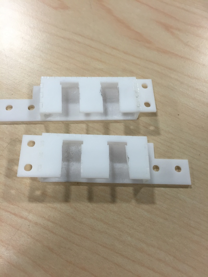
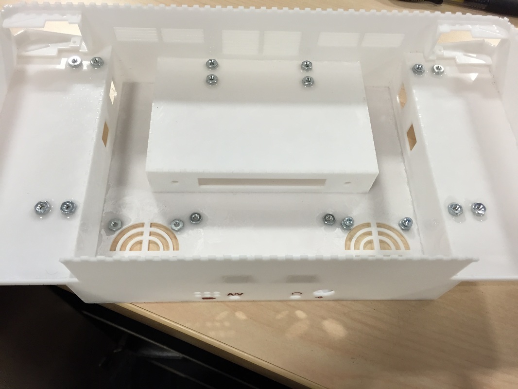
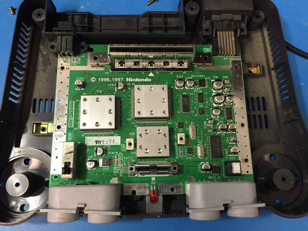
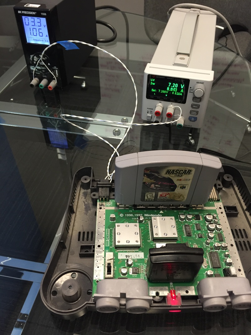
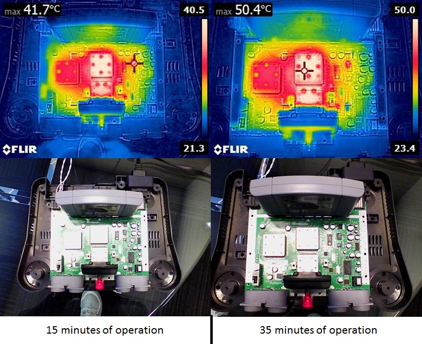
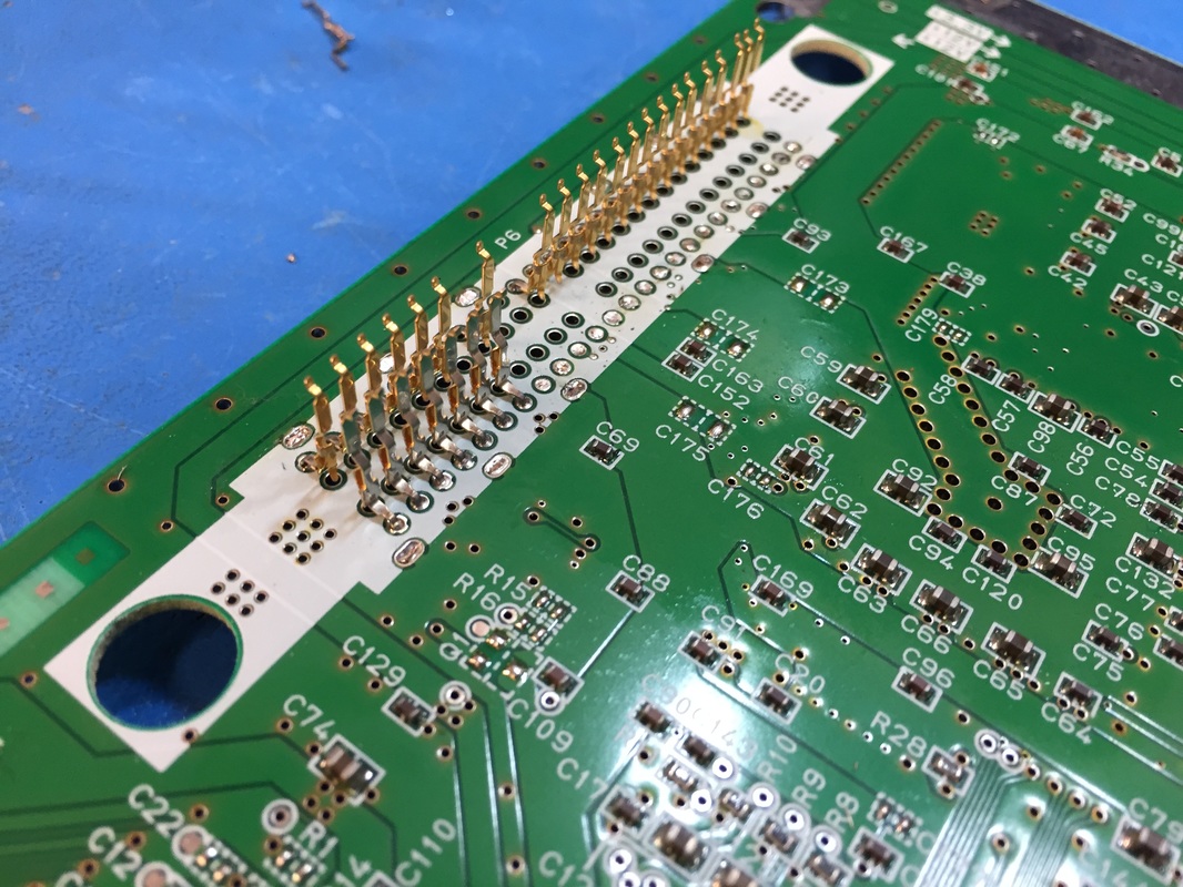
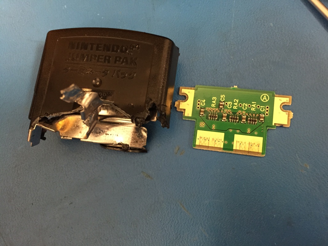
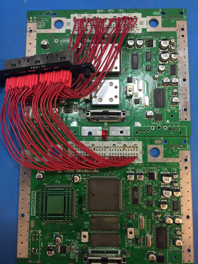
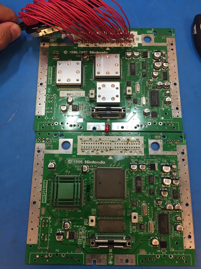
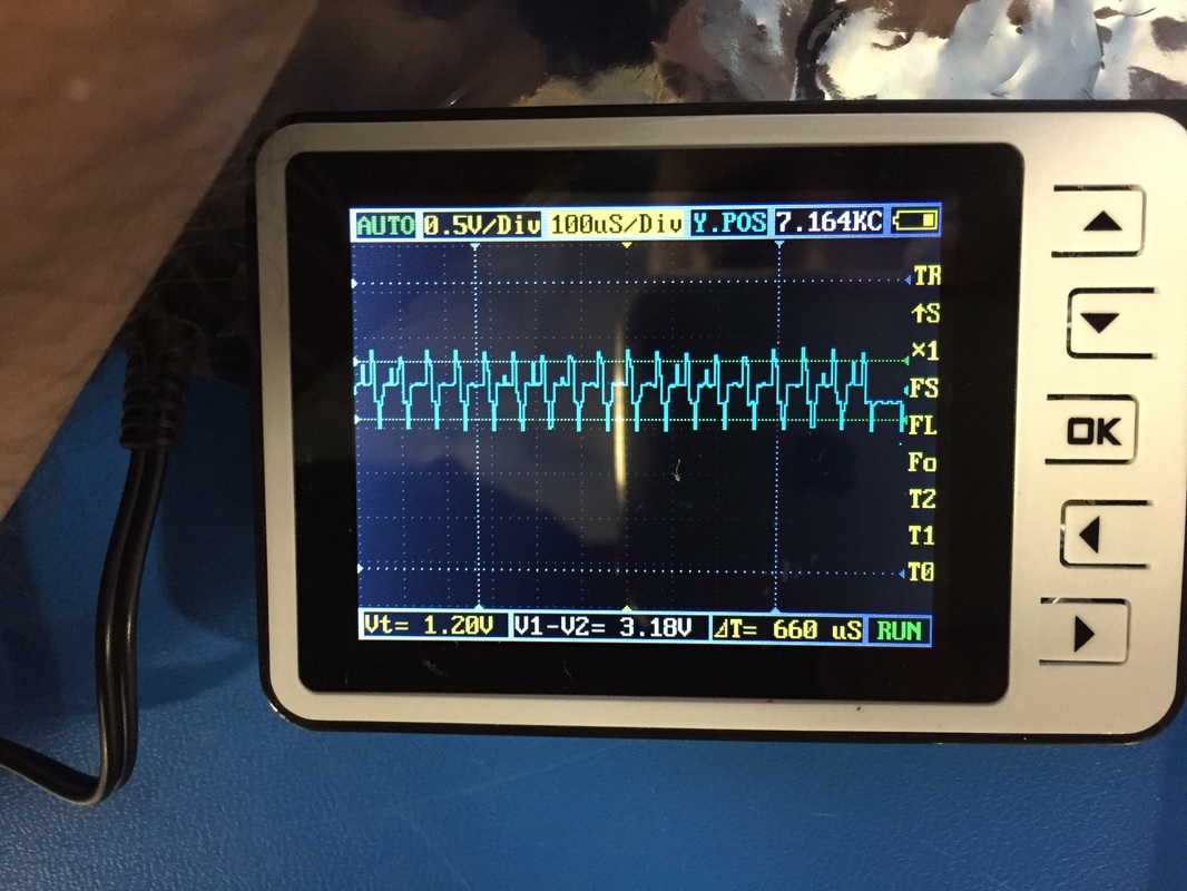
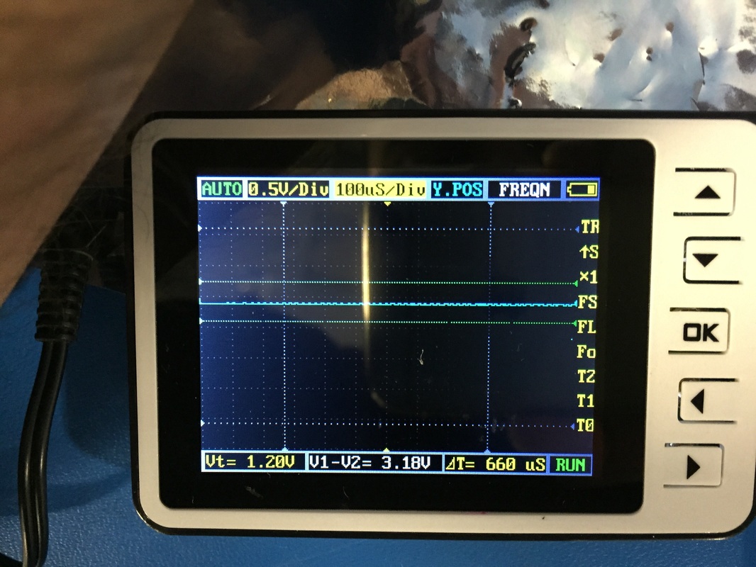
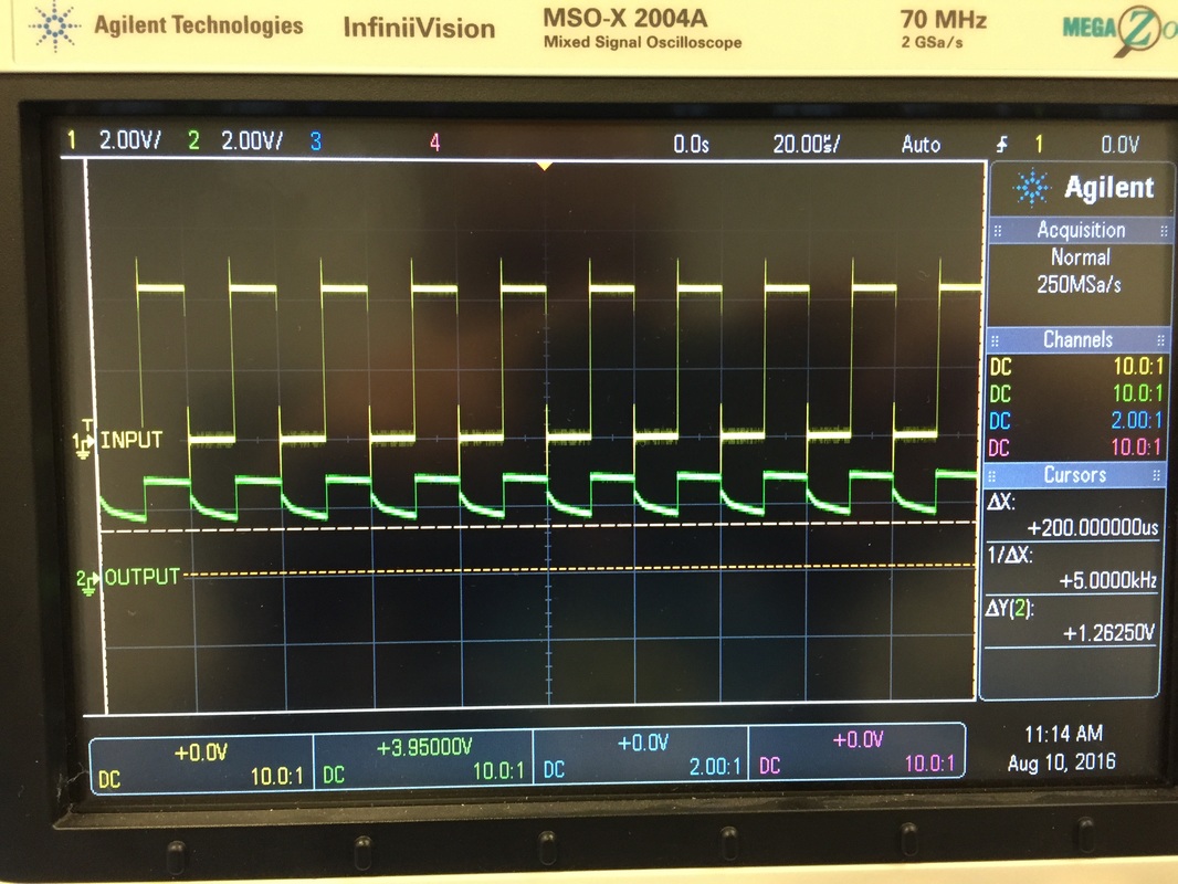
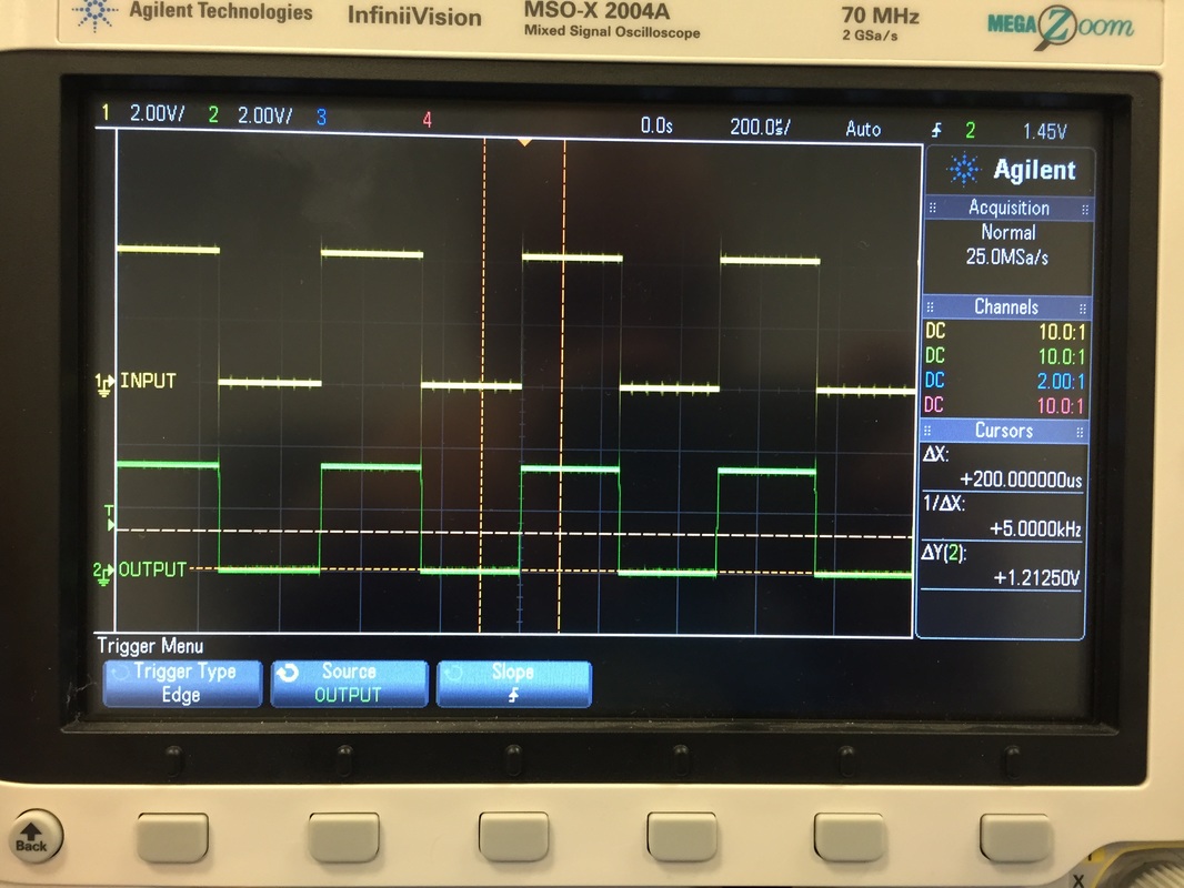
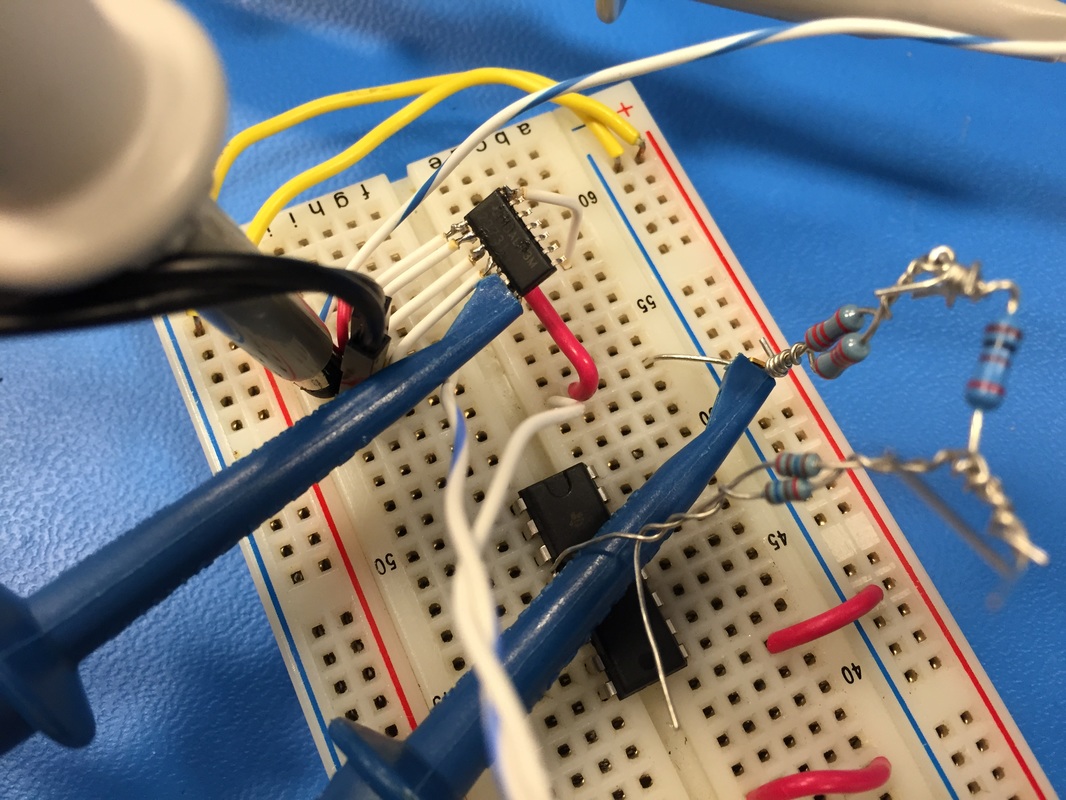
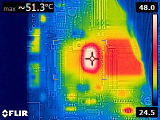
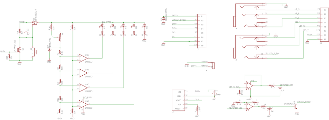
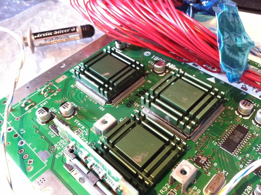
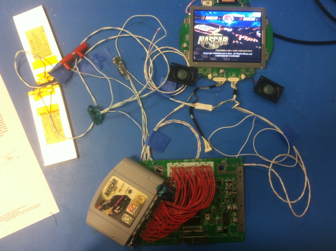
I'm ready to cut the final pieces now! Got a lot of the kinks worked out, got lots of gluing experience, and have proven that the pieces work all together relatively well. Next post should be the final one of the assembly and integration as well as some demos of the unit. See you soon! Battery Brackets Started with the brackets for the batteries so I can position the PCB's finally, The brackets proved to be a bit crappy design since the opening for the wires were too small and the tabs for the batteries too rigid. Ended up dremeling wide channels in the bracket where the tabs and wires would come out of the battery and bracket. It still proved to be stiff so I'll update that in the Illustrator file. Buttons While I let the glue on the nuts that hold the battery brackets dry I focused on the face plate and buttons. First wired up all the controls on the control PCB and connected some stuff to test the game still works, check. Then I cut up the button's rubber membrane for each button. I found that they kept slipping when I pressed the A button so I ended up hot gluing the membranes to each of their button bottoms. Hot glue is not really seen and its easily replaceable. After I did all that the buttons didn't slip and contacted the PCB a lot better. The A button is still a bit finicky but it'll do for now. First go at Integration So I after all the glue cured I put everything but the N64 board into the box and tried to test it all. With the Battery brackets in I could finally put the power PCB in, then connect the N64 and screen wires to each other. DIdn't try too many buttons but the few I tried worked just fine. My general plan is to integrate with long wires, try it out, then replace with shorter wires custom for each length. Run the Unit Connected everything with the N64 outside and ran the game. It all worked! Even tried the rumble motor and it rumbles just fine. Cram More Stuff In! Now comes the N64's turn. Tried a million ways to integrate the game cartridge without taking anything out...failed miserably. Had to take everything out including the fans and main PCB and batteries so I could fit the cartridge through the slot. So now I gotta integrate everything with the N64 in the middle which makes me nervous. Currently holding wires down with blue tape (flash breaker) but I think the correct course of action will be lacing cord. Next big thing should be securing the controller PCB better and gluing nuts to hold that down, the one that goes all the way through the N64 will be a bit of a struggle. Can't wait... New Unit here Very excited to get back into it after about a week of down time. Took apart the new unit and hooked up wires for the power connector since I don't have the power module that plugs into the back of the console so powering it off of two power supplies. initial test worked so the unit is healthy. I took FLIR readings of the heatsinks that came with the unit to get an idea of how much heat the fans are gonna need to cool down inside the case. In an ambient room that's ~23 deg C with still air the hottest parts of the N64 reach ~50 deg C. Rise of 30 deg C is a bit much but can't do much about it, just be cognizant. I proceeded with desoldering all the connectors and stuff. Not sure if I noted how to desolder the cartridge easily last time. There are metal tangs around the perimeter that keep the shield grounded. You can cut those from the top connector and slip the whole connector out, the connector that holds your cartridge is not soldered down through the pins, just those metal grounding tangs. Then around the bottom side, the expansion pack connector can be slid off in the same way, the plastic connector housing will come off leaving the metal contact soldered down. Then you can go through and desolder each one very easily. I didn't have the screwdriver for the jumper back so had to break the case. Seems like the one that came with this new N64 is made by Nintedo (original N64 I bought didn't have that writing... maybe it was counterfeit or cheap knock off?) Rework With the N64 board cleaned and nudered of connectors I went through each wire of the cartridge connector and transferred from old N64 to new N64. Pretty simple job, some wires were a bitch because you can't heat it up to much or else you'll melt the plastic insulation but the ground contacts can really sink some heat!. Tested the unit again and it all works, no mistakes made. Hope I don't have to do that again... Back to debugging PCB You can see the composite video signal in the first picture, I'm looking at this on U2 pin 3. But when I try to see the output of that first opamp on U2 pin 1 the signal is not there (picture 2). After a lot of headache and looking at the datasheet for the opamp (TLV2373) it seems that the shutdown pin can't quite stay high if left floating. The datasheet explicitly says that if left floating or tied high the opamp works but that is not the case and it needed to be tied high. So I jerry-rigged another clone of the opamp on a breadboard and fed in a square-wave with the DSO nano v2, You can see in picture 4 that if the shutdown pin is not explicitly tied high the output does weird non-opamp stuff, but picture 5 is the opamp clearly acting as an opamp when the shutdown pin is pulled high. After I wight-wired the shutdown pins high on the main PCB I hooked it up to the N64 and screen to see if the whole thing worked. I had to tweak a bunch of resistor values to get the correct control. So R17 was changed from 1k to 110k to really dampen and incoming signal. The starting screen output gave me a DC RMS of about 180mV with not too much pk-pk. With that R17 so high and the DC RMS at 180mV, the second stage amp had to be bumped from 3x to 10x so I replaced R18 from 2k to 9k. This ensured that I'll have a signal that's above 0.6V for the transistor to turn on. Lastly, I changed R20 from 1k to 110k so that the output signal was filtered and did not flutter to fast. One problem I was having after changing R17 was that times when the screen was dark the signal was so low (around 90mV) that the screen was being turned off. So had to amplify and filer just right to not have the screen turn off even if there isn't much activity on the screen because a black screen is still a signal just a faint one. Sadly I didn't take any pictures of all this but testing it proved me right. I'd turn on the console and the screen was on, would plug in the A/V jack and the screen would shut off. I even tried it with no game and the screen was on when the jack wasn't connected and off when it was so my circuit correctly told the difference between a blank screen and a black screen. Onward I tested the full unit with a range of voltages, found out that the screen starts to be squirrely around 6.8v so I adjusted the battery indicator to turn off the last green light at 6.9v, turn off the second green light at 7.5v and first green light at 8.1v. Now there is two things I can do: build battery holder brackets so I can start assembling stuff into the DTV case and do testing, or I could cut some acrylic and build a small jig to test the controller port fin so that the case doesn't break apart when someone uses the controller ports. Woohoo! Testing PCB's I finally finished all the PCB's and tested them. Mostly they worked, only one circuit needs further investigation.
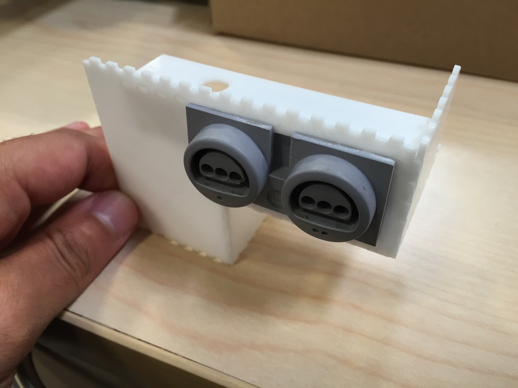
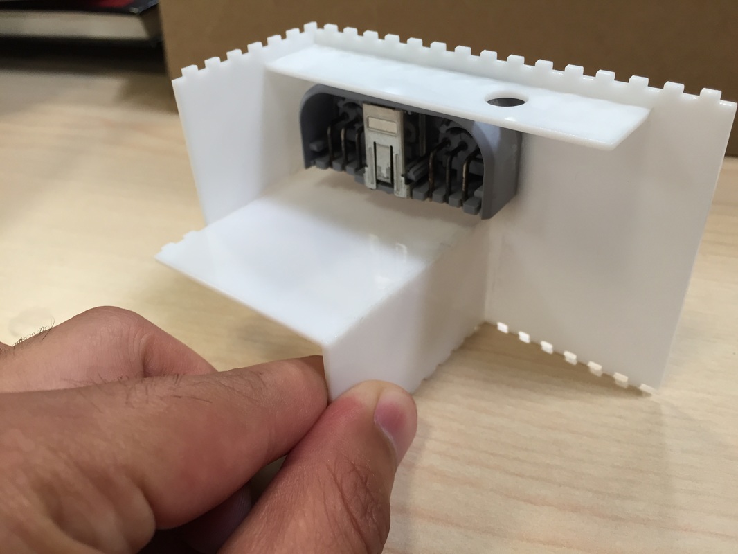
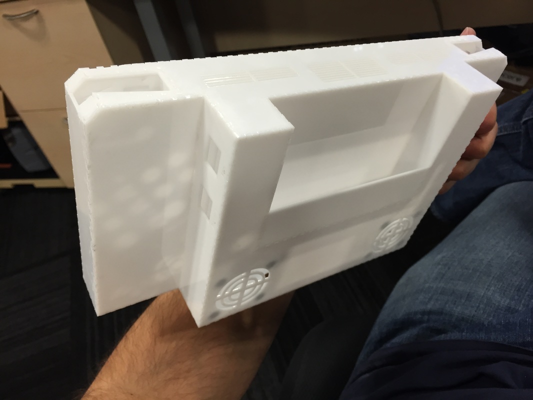
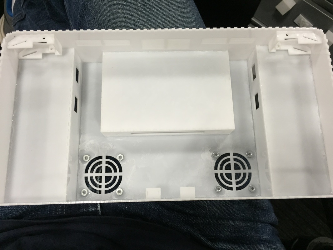
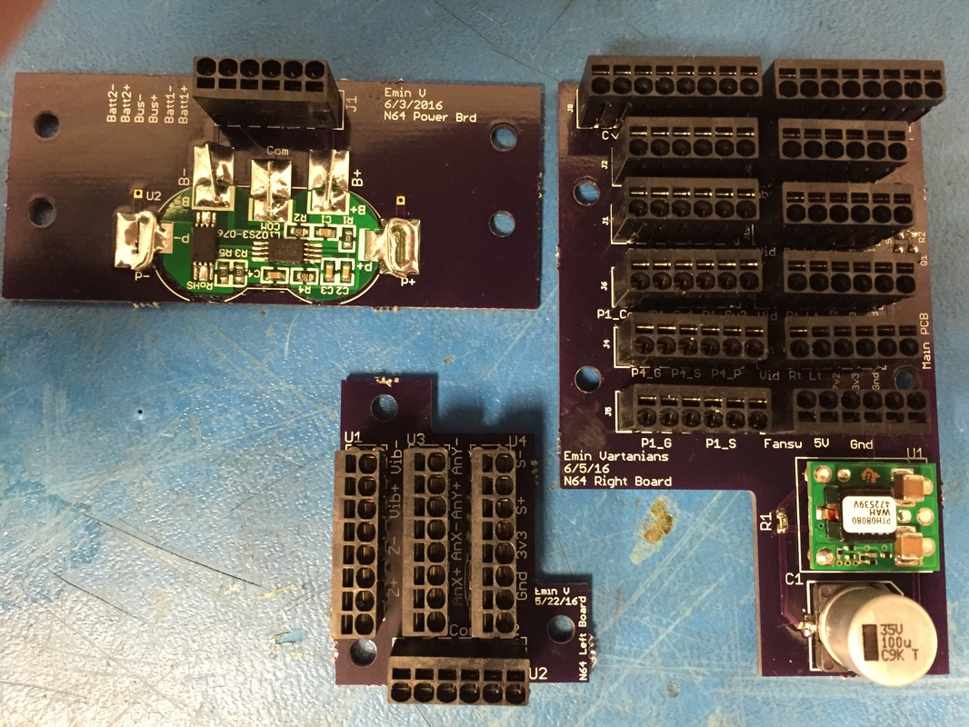
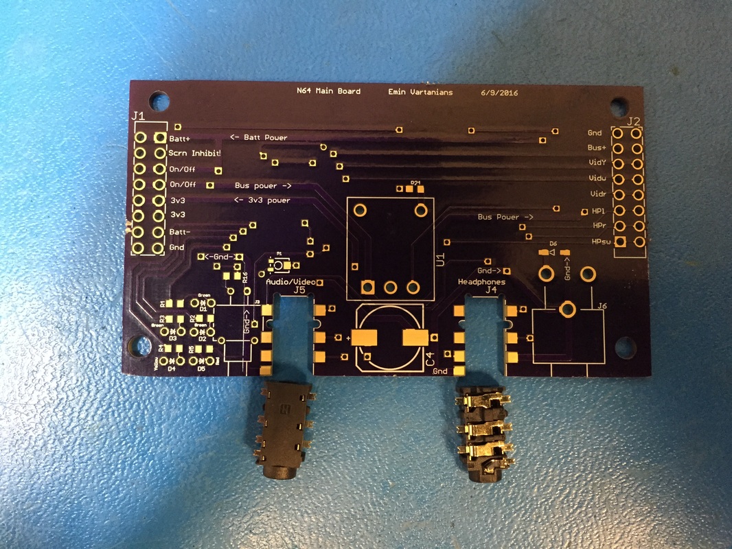
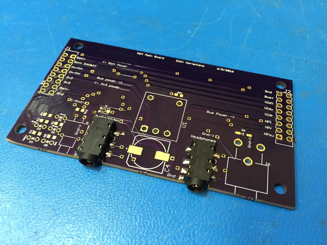
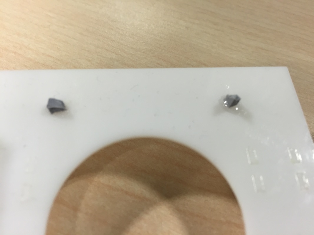
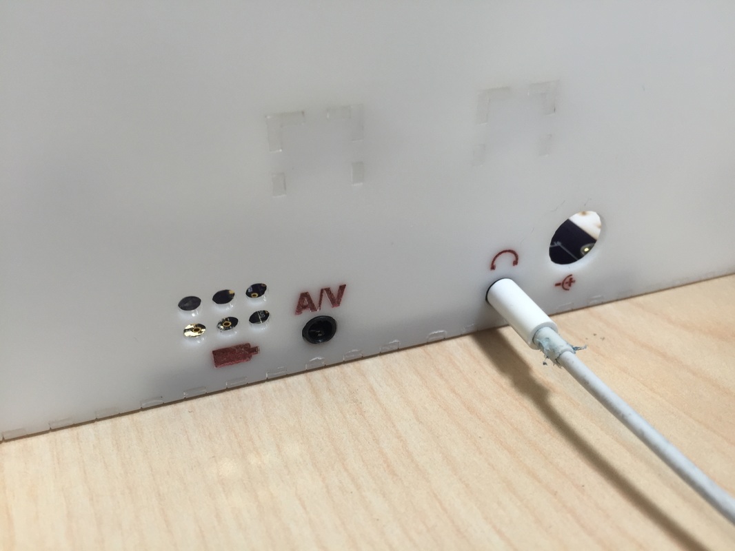
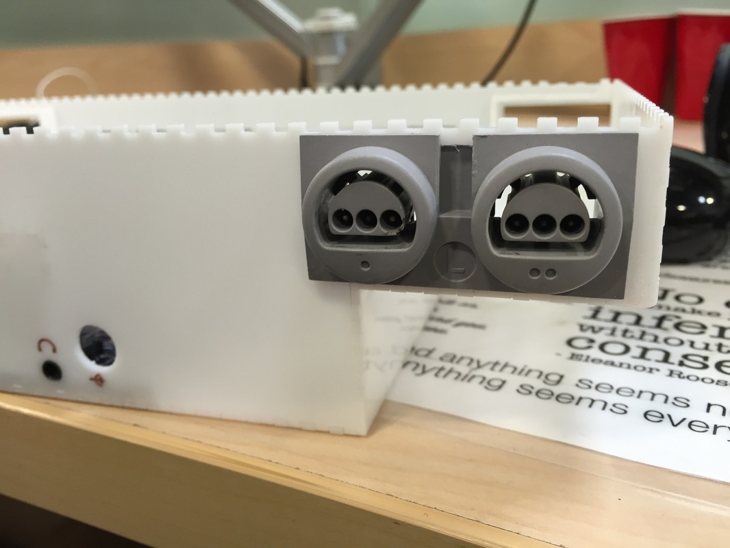
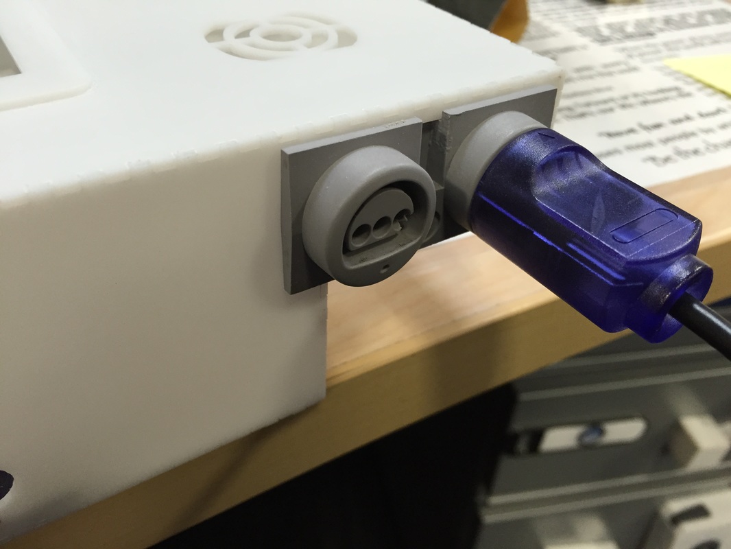
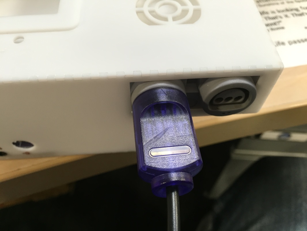
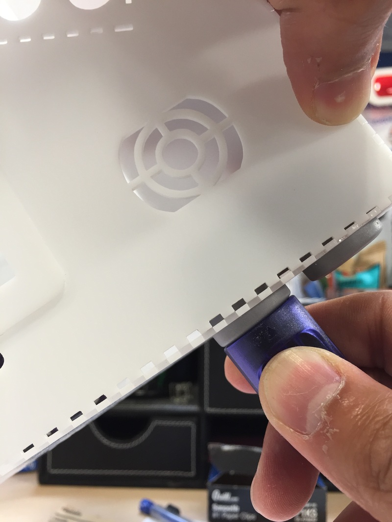
Killed my N64 I think I killed it by being cocky. It was 2:30AM and all my tests were passing, so I got too sure of myself and was not grounded and touched the N64 heat sink on the RAM modules and the screen went blank. Power cycle did not fix the problem. I should mention that earlier I had accidentally plugged the Jumper pack (Ram Bus) backwards so the 3.3v was shorted to ground. Took me a while to figure out what was messed up. So maybe its just that little PCB that's fried. I couldn't see any visual indication of stuff messed up. The 3.3v regulator is pretty smart and protects against over-current conditions and recovers in "hiccup" mode where it tries to bring the voltage back and cuts again if its shorted. Either way after the screen went blank it never recovered. I saw took off the heat-sink on the RAM modules (RDRAM18-NUS B) and took some heat readings with the FLIR. You can clearly see that one chip is getting way hotter than the other. I looked up the part and found other people talking about it, at the bottom of the page you can find the Datasheet for a very similar part. I used that to scope the output pins. No activity on the Data lines, and the clock was barely oscillating. So I'm pretty sure the whole board is busted. Plus I was careless and got thermal paste on the pins of the components... that stuff is conductive at 99% pure silver so shorting can occur. I bought a new N64 on ebay for $40 including shipping. I was very happy to find something so cheap. The worst part is gonna be de-soldering stuff again and soldering the cartridge connections, those were painful. Will fix the screen inhibit circuit before I start hacking the new N64 board... provided its not dead on arrival. Test Box (DTV) Decided that since I had a bunch of the parts already cut out, I'd go ahead and finish the 3D model translation to illustrator and cut out the remaining pieces I need. I tend to be very conservative with risk and having a "draft" case where I get to test stuff out is crucial. In the aerospace world we sometimes call this a Dynamic Test Vehicle (DTV) where you build the shell of a spacecraft and see if the structure holds during testing and fit checks. The build was pretty good, not a whole lot of problems, just had to figure out how to set stuff down as the glue cured. The faceplate is not glued as it will be held on by friction and magnets. Some small parts in my illustrator file have to be redone since I made some mistakes in the translation. But mostly good. I'm gonna start mounting some stuff in here to see how well they mount and how hard gluing all the nuts on here are gonna be. The screen is already proving to be a pain in the ass to locate holes and glue. I noticed a lot of glue vapor etchings around the interfaces. I think the possibility of me messing up is high and I don't want to take the chance of some vapor or glue smudge being on the case so I've decided to sand the whole case after assembly. I start out low at 80 grit then work up all the way to 800 grit in circular motions. This dull's the shiny white but is still really smooth to the touch and gives me a way to fix any mistakes during gluing. Printed Circuit Boards Got the PCB's in from OshPark and they are prettyyyyyyy. Populated the 3 easy PCB's and only did the 3.5mm jacks on the main PCB to make sure the solder pads were strong enough for me to plug in and out the connector. Haven't tested any of the boards yet, will need to do so before they get integrated. Bottom Panel Plugs A big thing I worry about is if the glue holds for me to plug stuff in and out of the headphone/AV jacks, Battery charger, and multiplayer ports. The Headphone and A/V jacks were surprisingly strong. I mounted the PCB down on the inside of the back piece and screwed it down. The 3.5mm jacks are in the perfect place, the Battery charger port is a bit too large, my mistake in CAD, so gotta fix that for the final version. Was worried about the controller ports 1) gluing to the acrylic and 2) ripping the case as I plugged and unplugged. To get a better handle on the first worry I glued a couple small pieces of plastic I cut from the controller port onto a sample piece of acrylic. They hold beauitfully so I have faith in the controller port not separating from the panel. Next worry is that the panel will break apart. Since I only have one set of controller ports I can't glue these and find out, but if I position the port in the place (as seen in the 6th picture) I can test plugging it in. It wen't beautifully, no cracks, no sounds. Then I had to pull the controller out so I positioned the port behind the cutout inside the case (as seen in the 8th picture) and tried to pull it out. As you can see in the last picture the bottom piece bows out a bit to the point that I have to put my finger at the top of the port so it doesn't break. I think if I put a brace on the inside of the case running like a spine down the top of the case then It'll stiffen up that interface. Next Steps
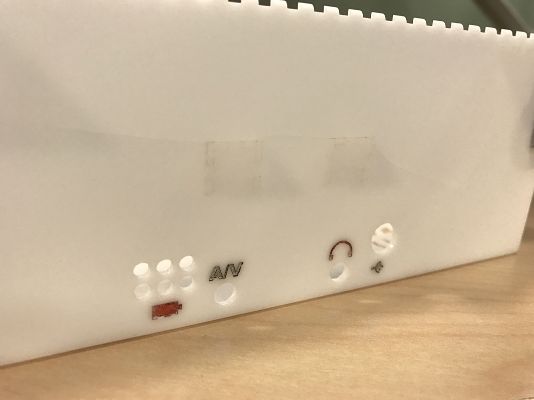
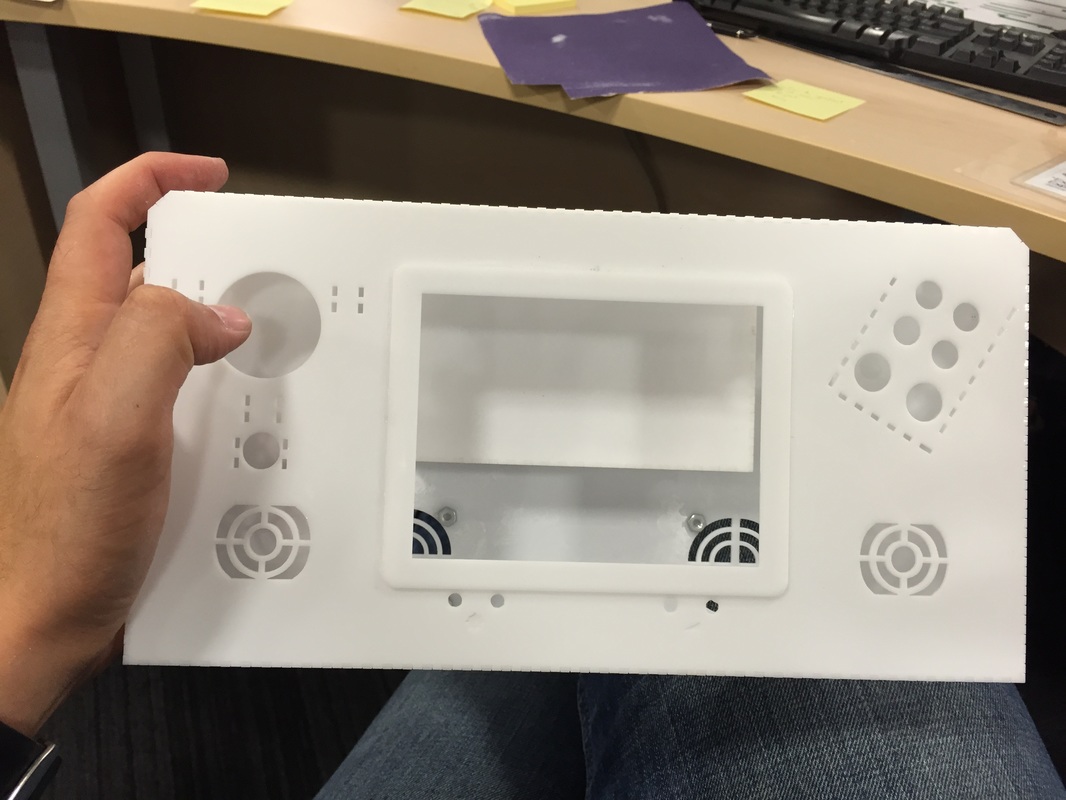
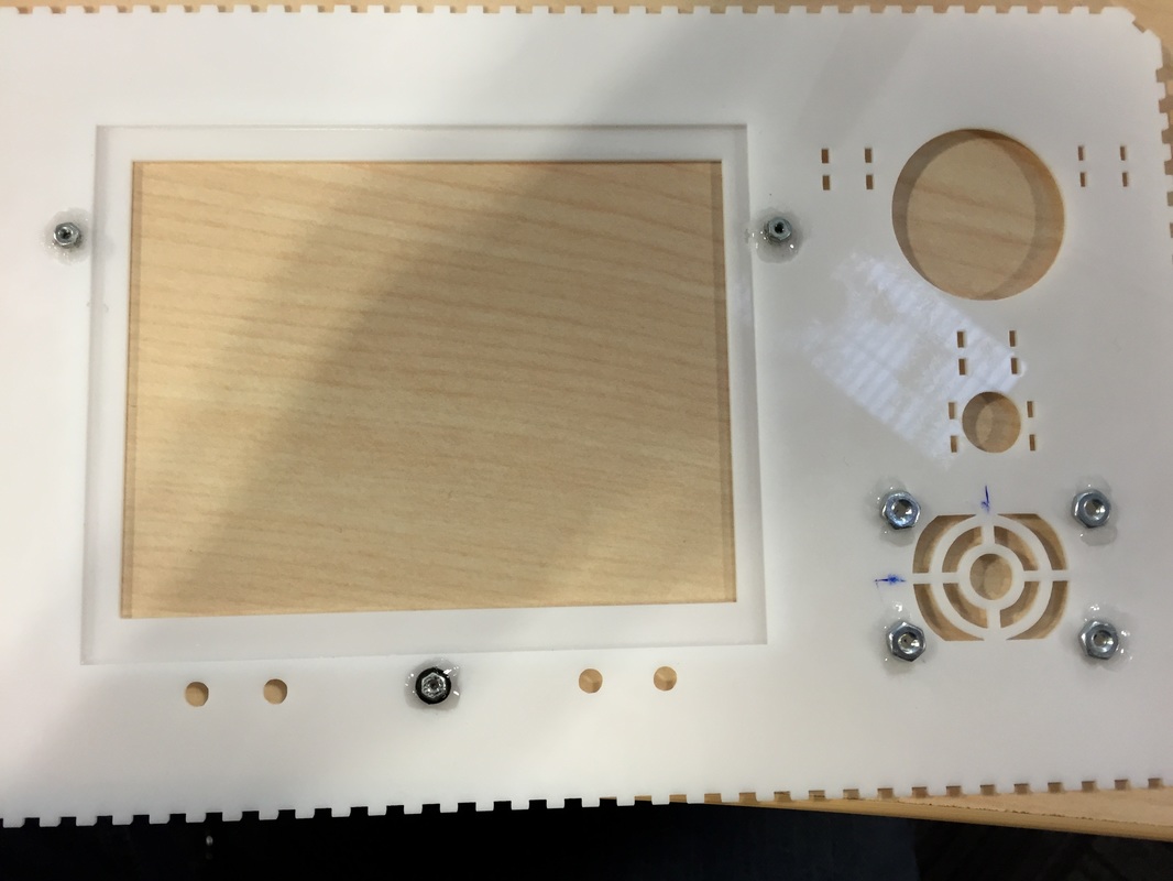
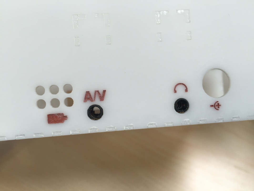
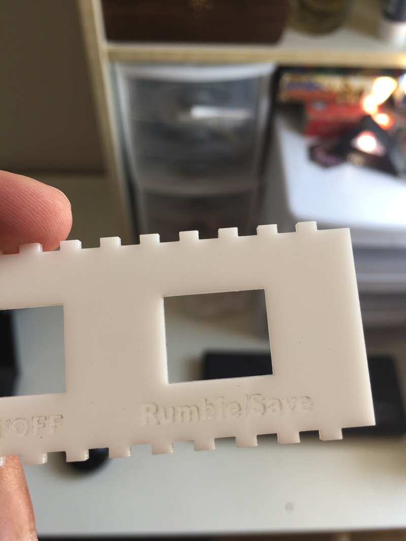
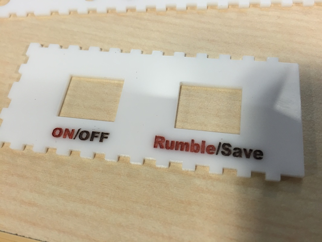
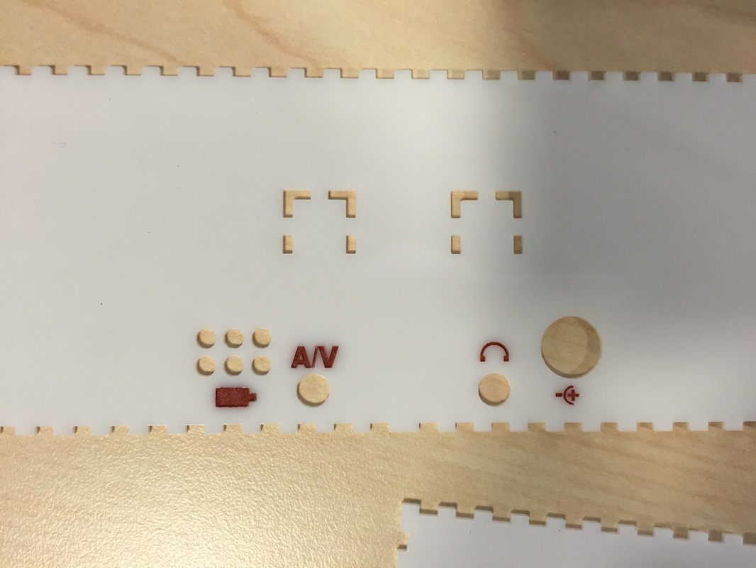
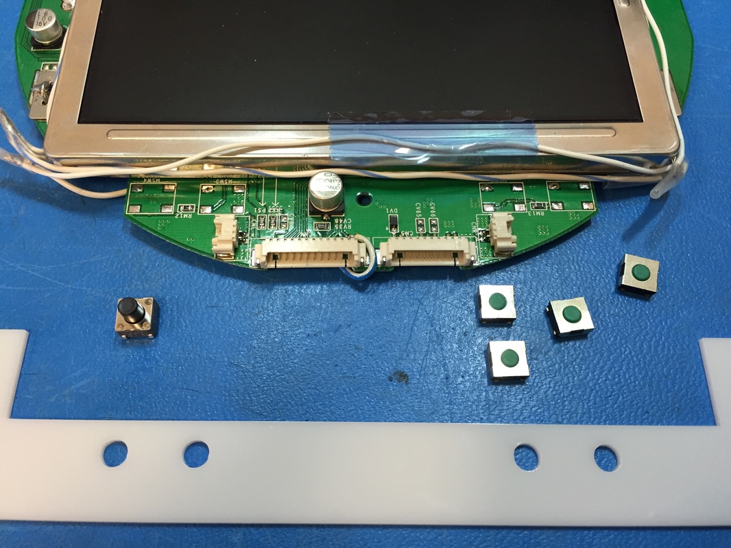
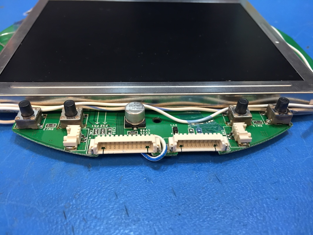
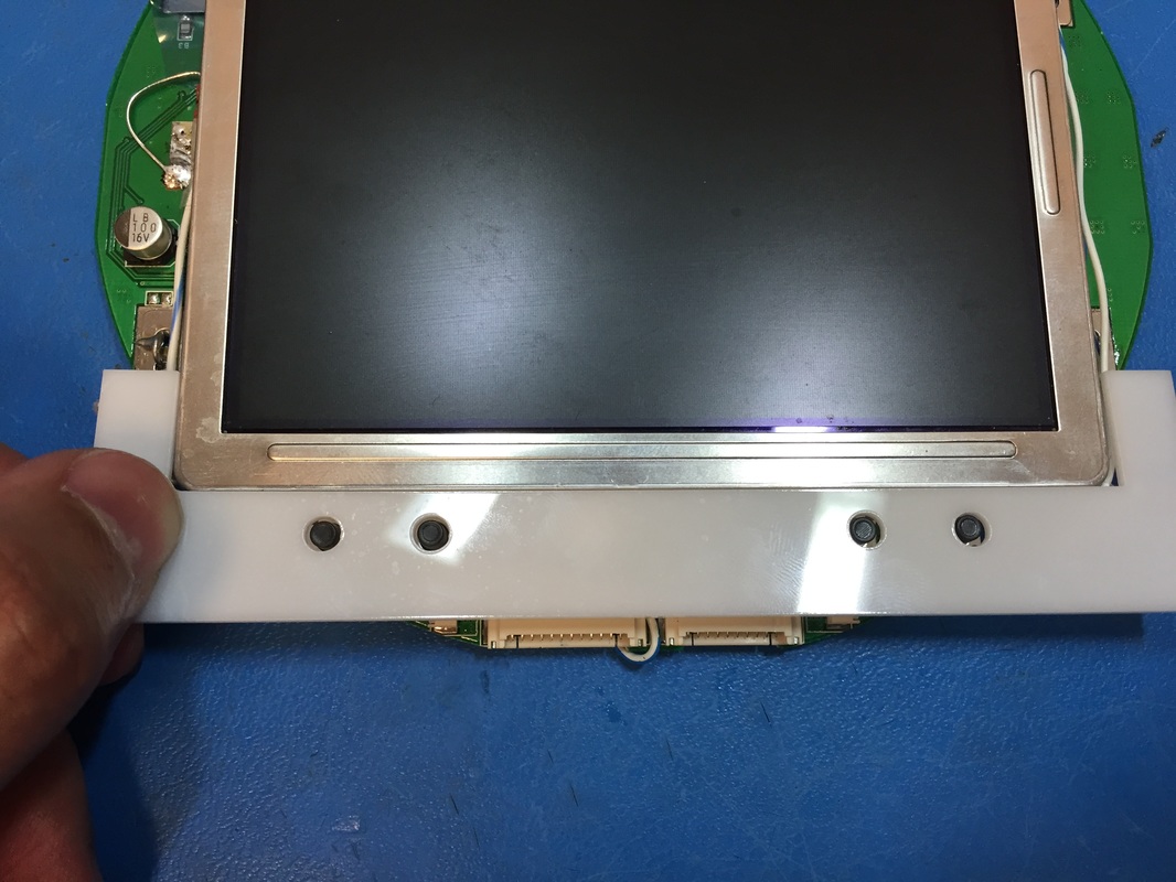
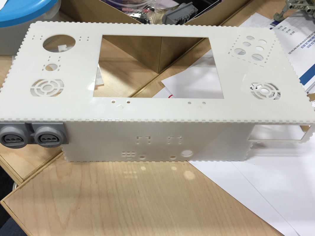
I'll have to finish up the main PCB assembly and test out the boards individually. Then do an electrical connection test on all the interfaces. This will be just like the final assembly just not in the case. Once I know that all the electronics work I can focus back on the case. I've also Gotta cut that spine and retest the controller port real quick. Then assemble the battery holders and stuff so I can integrate stuff into the DTV. Once it all works I'll update the illustrator file and cut the whole kit one final time. Decals and Paint Asked my girlfriend for some help with the decals. The symbols/labels are engraved about 1/3 of the way into the acrylic with the laser. My original notion was to use a pen or something to get fine control of the engraved part but my girlfriend suggested acrylic paint. With a fairly wide brush I was able to paint a blob over the engraved parts as well as the surrounding non-engraved parts. Then after a few seconds I just wiped the remaining paint off with a tissue. The engraved part is very rough since it's been hit by a laser at 1000 dpi but the non-engraved part is really smooth, so the paint sticks to the engraved portion really quickly and don't have a chance at sticking to the rest of the perimeter. All in all I think it came out really great for test pieces. Screen Buttons I ordered this button off of digikey. Because of its plunger height it just sticks out above the plane of the case. So I de-soldered the old screen buttons and tacked on the new ones. I made a small mold of where the button holes will be based on the corners of the screen. Then I used the mold to position each of the buttons and tacked them on. Didn't want to fully solder them since I might change my mind about the hole size or tolerance. The holes seem a bit big so I might go with a smaller diameter, we'll see after the first real front plate. Test Face Plate Cut out a first draft of the face-plate. First time that I could hold the whole thing in my hand and get a sense of how big its gonna be. It felt pretty nice, just gotta make sure the case is sturdy. A few things needed tweaking but all in all it was good. I think I'm going to build up a mock-up of the case using the back part that I messed up a month ago. It'll give me a chance to practice with gluing and integrating things. Full Project Laser cutter Outline I've arranged the full project in a PDF ready for the laser cutter. I'll cut parts of it at a time to not waste acrylic if something needs changing. I've added long thin pieces which will be glued on the inside corners of all the interfaces to give the box more rigidity. I'm scared of the glue breaking when I plug controllers or headphone jacks in and out. Once all the PCB's come next week I'll do a bit of a pull test to see if the mounting screws and nuts can even tolerate me jamming jacks in the connectors or if the super glue with break after a few times. Can't wait!
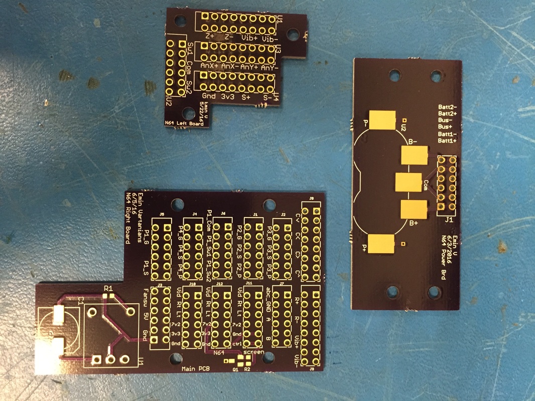
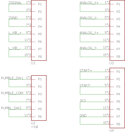
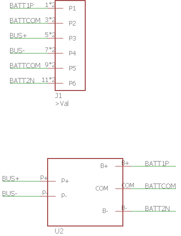
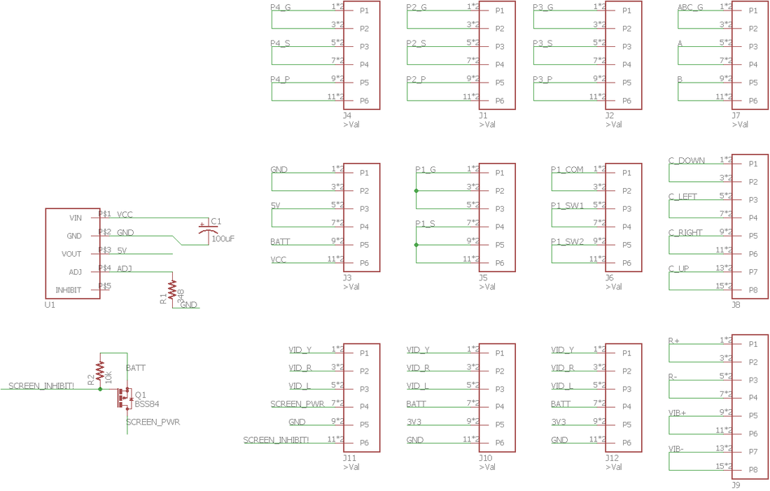
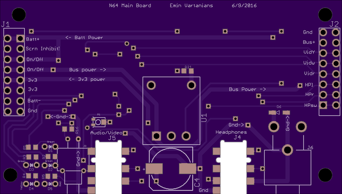
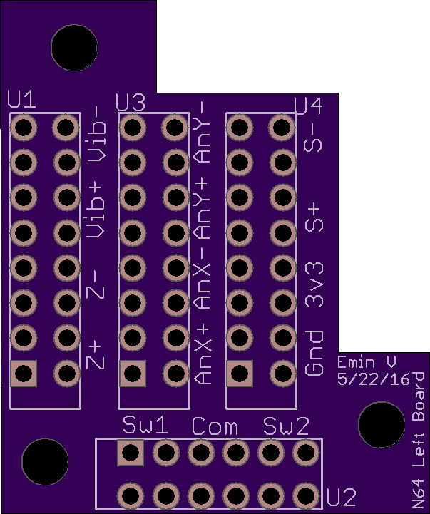
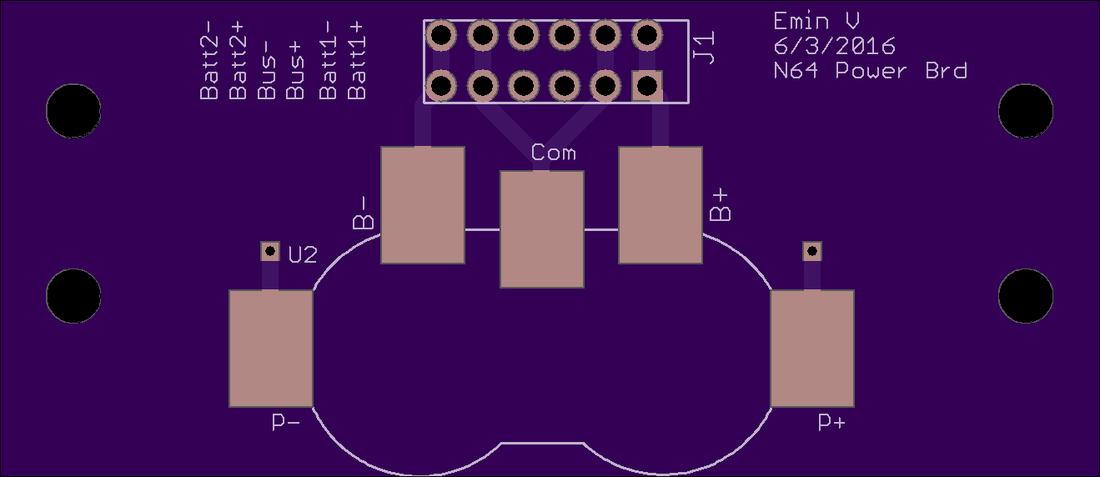
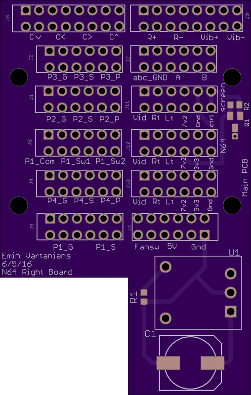
PCB's Spent a week or so doing PCB's. I used EagleCAD to make the schematics and Layout then used OSHpark to actually get the PCB's fabricated. They do it for really cheap and you can just submit the ".brd" file from Eagle. My electrical engineer brain is really embarrassed at the level of these designs but It gets the job done, sorry if they are hard to understand. The electronics are split into 4 PCB's.
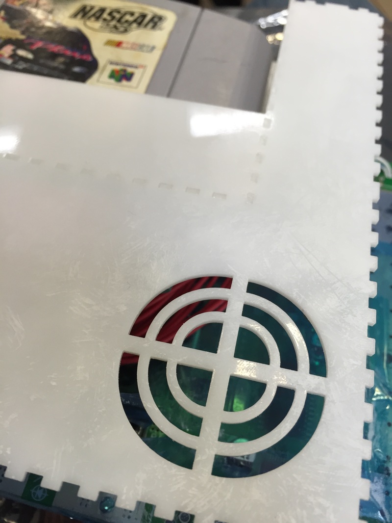
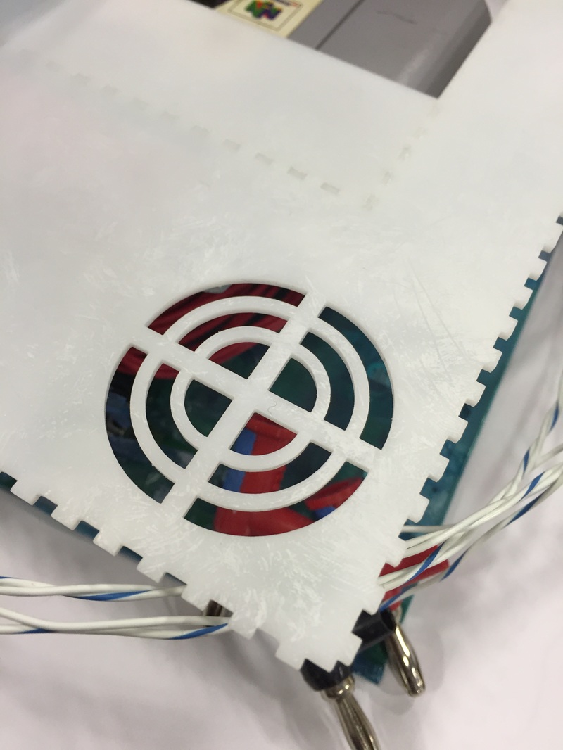
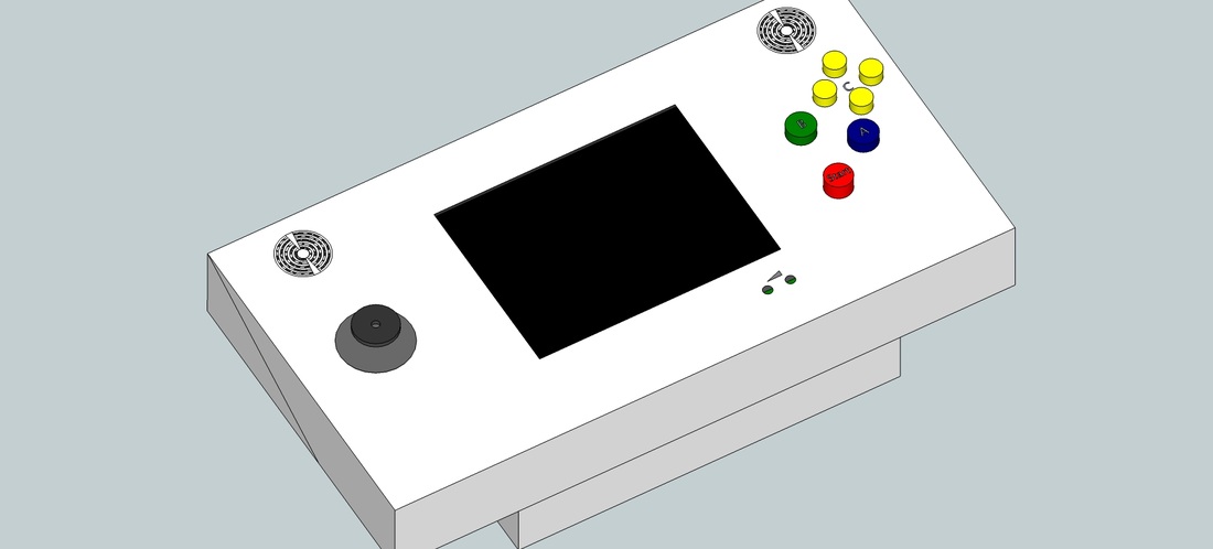
I've also ordered parts on Digikey. I had some parts already in my scrap bag (like a rail to rail opamp for the video signal sensor). I hope I had enough patience to put together a final As-Built bill of materials at the end of the project because I've changed small things in the block diagram I posted last time as well. Once the parts come in I can hook everything up and slowly build up a flat version of the N64. Once I know everything works through the boards I'll integrate it into the case. The Case I added these 4 PCB's to the model, added air intake vents at the top and added little holes for controlling the screen. There's a little blemish at the bottom of the case since the N64 has a bracket on the inside which is not centered so I've temporarily places a small plaque that has the N64 logo on it. We'll see what I end up putting there. At this point the case is pretty much done. I'm gonna cut some a test piece of the bottom which will let me test the holes and controller ports. After that I'll be ready to cut all the parts as I wait for the PCB's and components to come in. Next Steps Gonna wait for the digikey parts and PCB's to come in, gotta order some nuts and bolts again based on the newest (and pretty much final) CAD model. Meanwhile I'll go back to cutting the case walls starting with the bottom face and try a couple attempts to etch decals into the acrylic as labels.
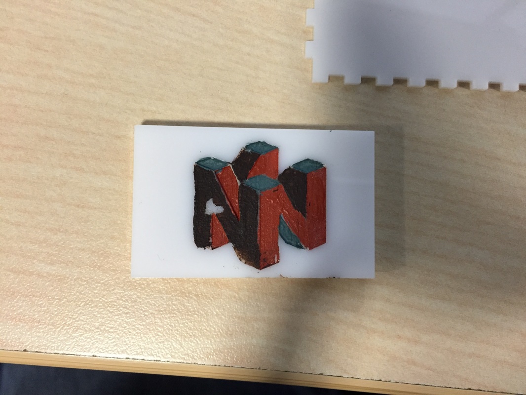
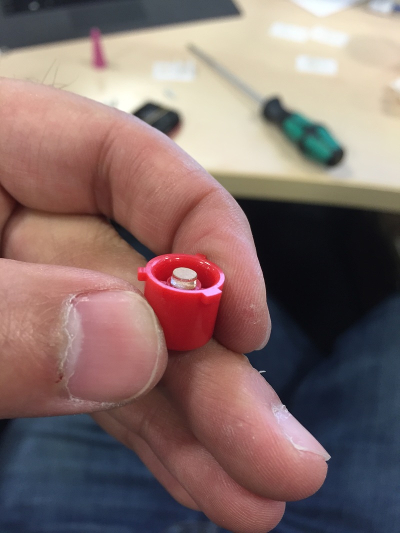
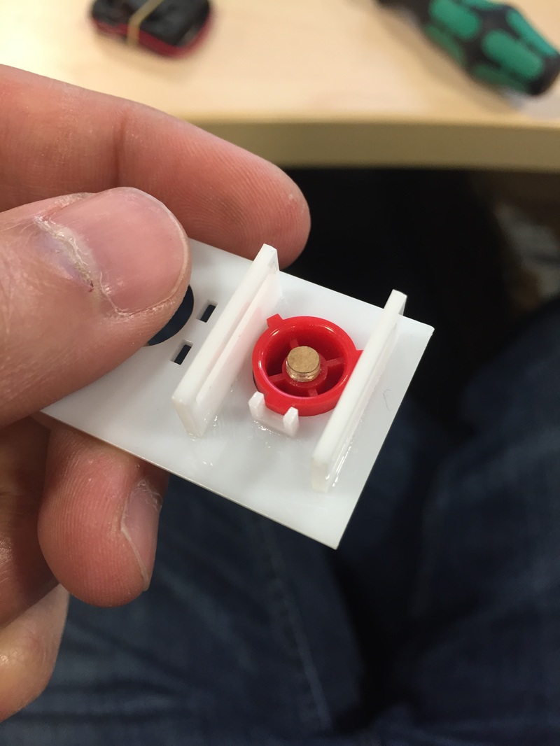
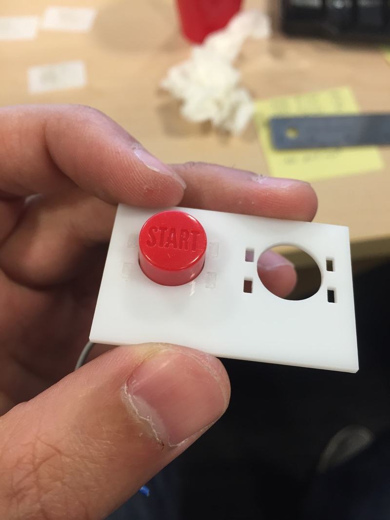
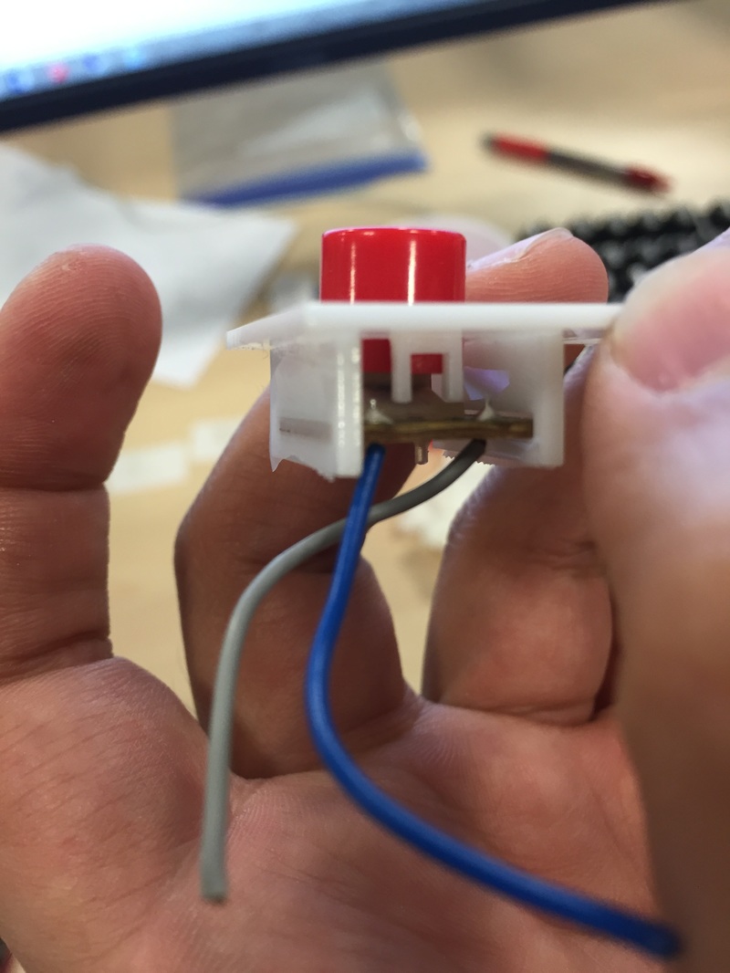
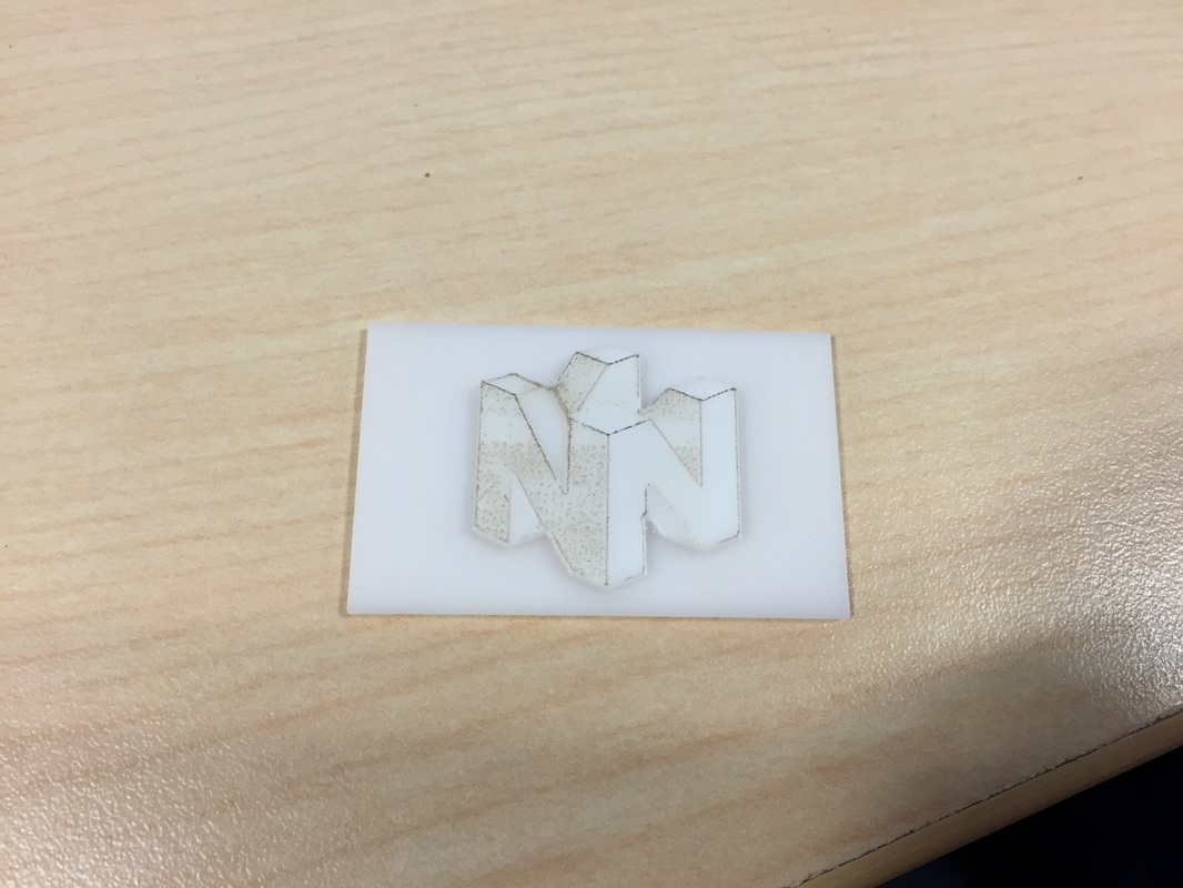
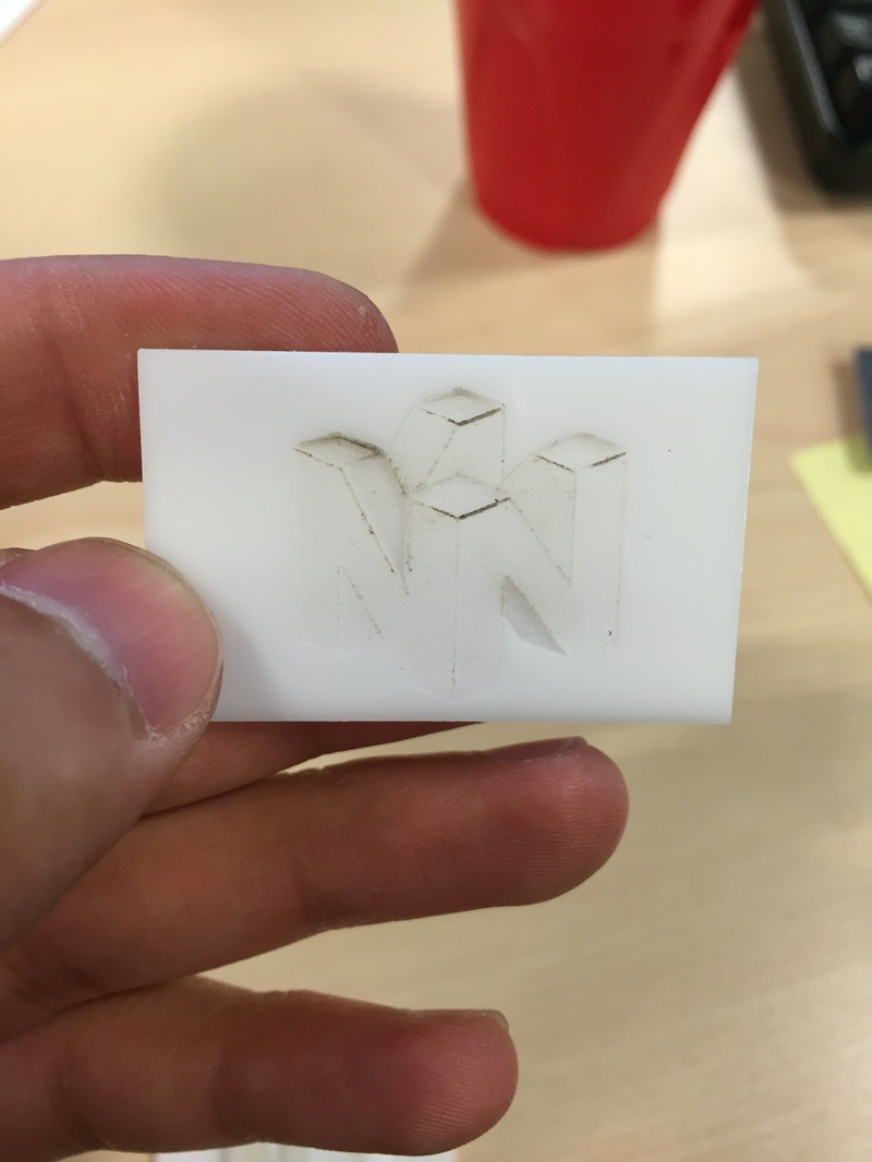
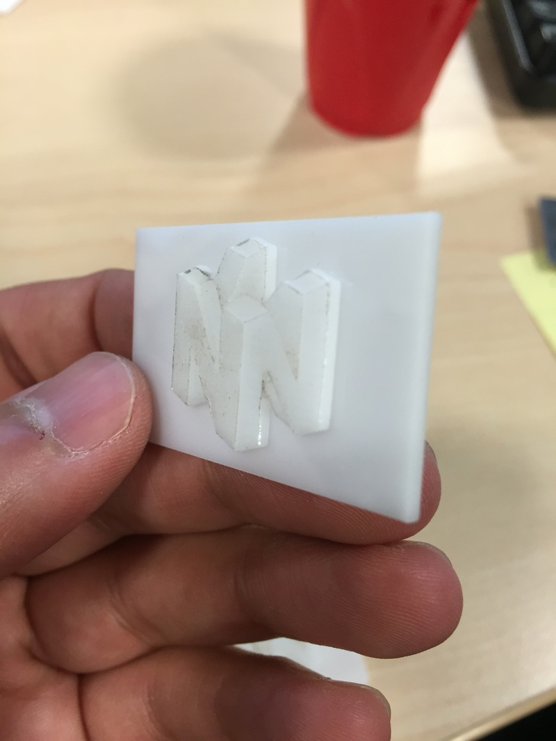
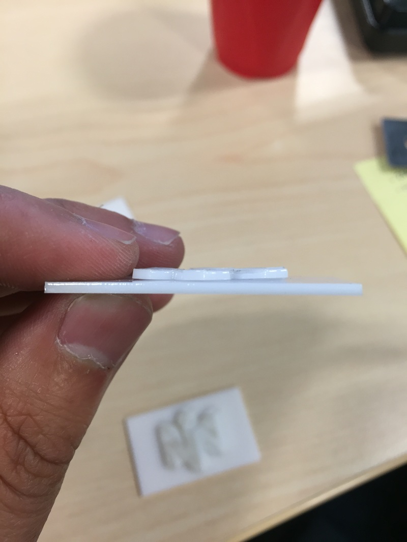
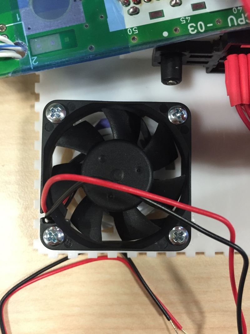
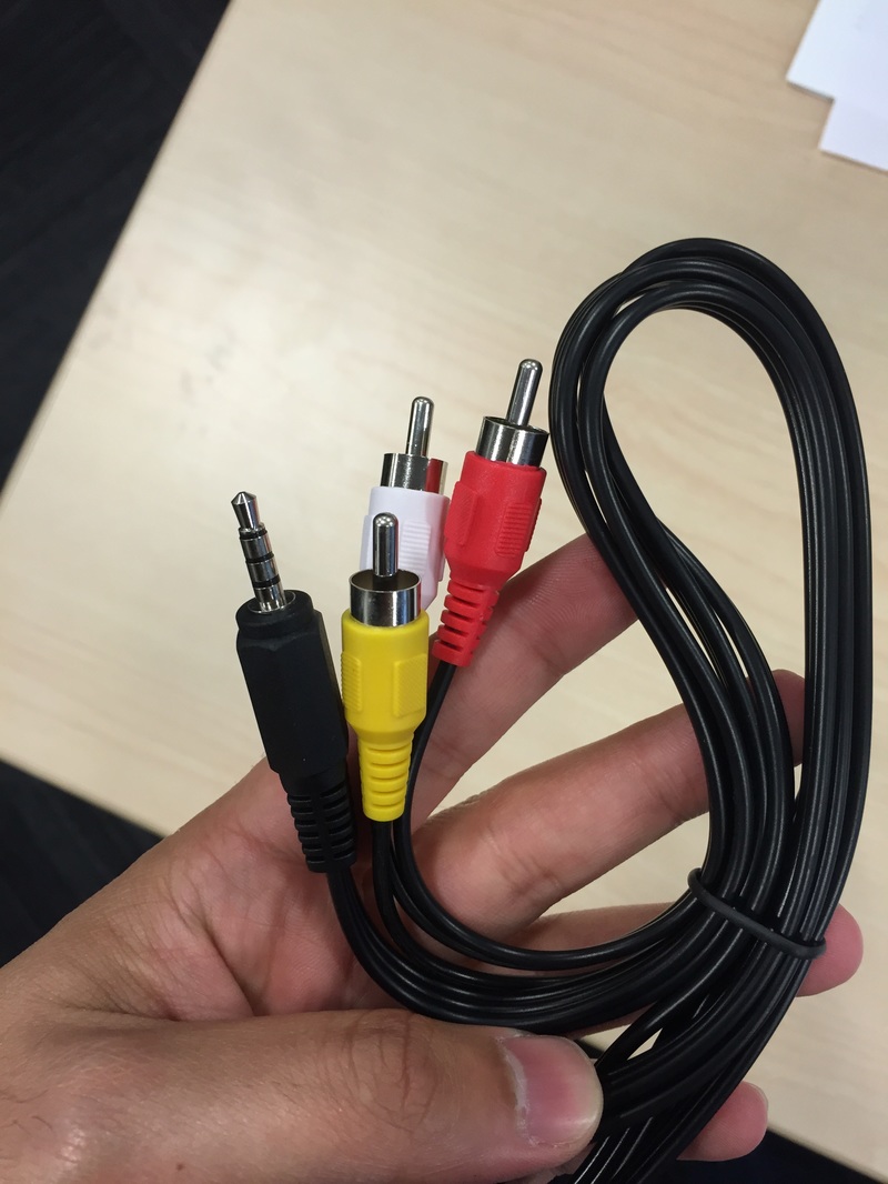
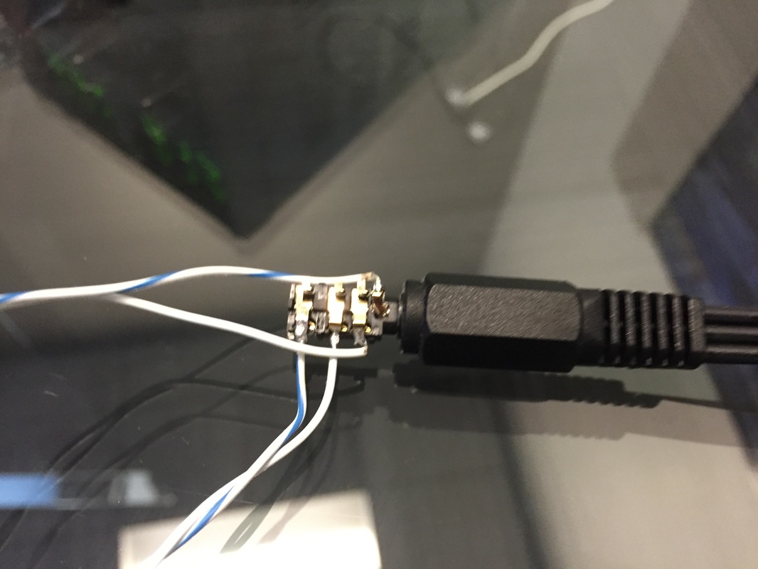
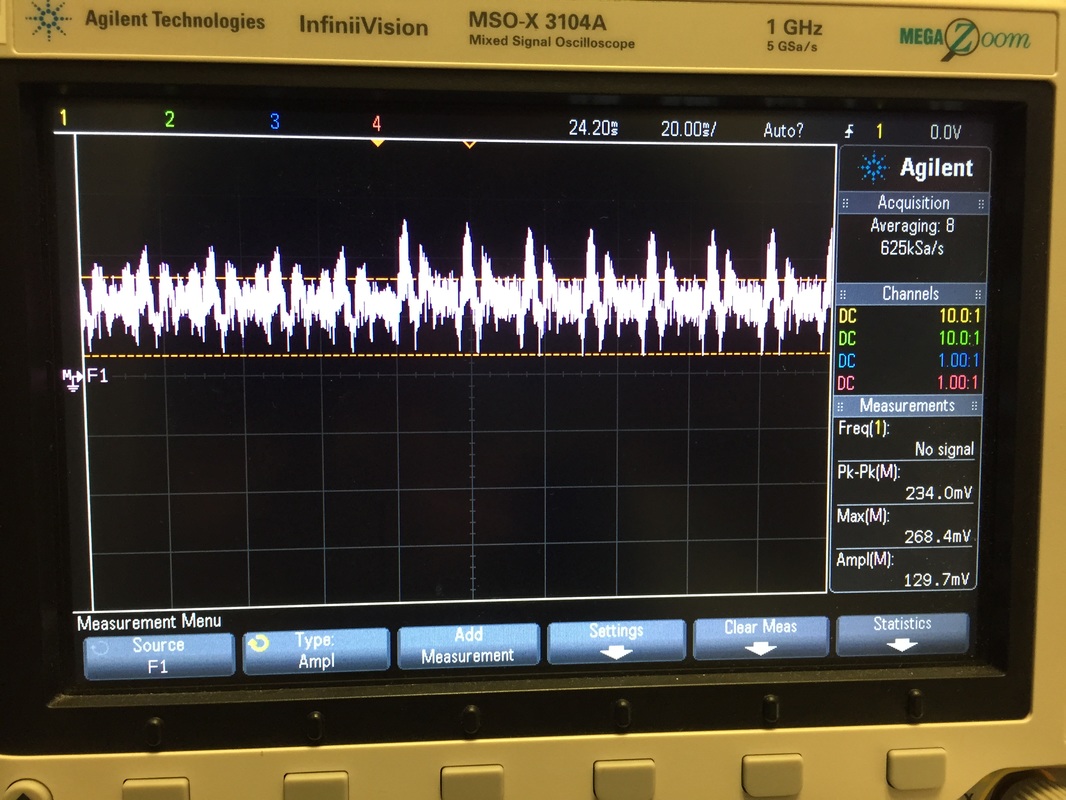
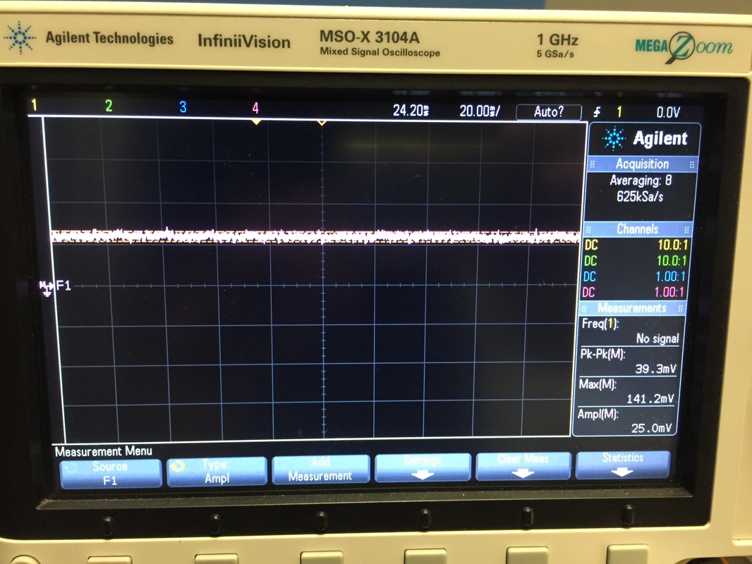
Start Button Started out with building a tiny bracket for the Start button. It's similar to the shoulder buttons in the way the bracket holds the PCB in its slots. Had to add a tiny piece under the Button to make it be able to actually actuate the membrane underneath since the button wasn't meant for the PCB. All in all it's a nice and simple design. N64 Logo Got a bit creative and wondered if I could engrave the N64 logo into acrylic with different power levels for each color (since the logo only has 4 colors). The results are neat but I wouldn't put it on the box quite yet. When I cut the logo outline out you can see a bit of warping from the engraving process, and in general the different power levels have a distinct depth to them but I can't really make the different sections pop which is frustrating. The only shading you see on there now is because the cover paper melted on to the acrylic. Will have to experiment, not even sure where to place it on the case. Case Bottom Cut the bottom part of the case that holds the game cartridge and glued it. This piece also has the holes for the two fans so I glued some nuts down for those (aligning those holes was pretty challenging).The whole thing came out really nice, The screws held everything really well and the gluing job was nice and clean. Used 4-40 screws and nuts to hold stuff down. Superglue needs to vent as it cures. The vapors will cloud up anything they settle on. I was an idiot and left the whole thing inside a bag overnight as the glue cured and came back to a messed up case.... will have to redo this bit. Audio/Video Jack Hooked the Component cable thru an RCA cable I bought which takes the yellow/red/white component inputs to a 3.5mm headphone jack with 4 conductors (4th conductor is ground). From here I wired it to the S video and audio coming from the N64 that would normally go to the screen and took it to the audio jack. Magically, it worked without blowing up the unit or the TV! very excited. After a little research I coworker found that the S-video signal goes to a minimum of 0.285v so if I can amplify that signal I can tap it off the switched side of the connector (remember the barrel connector I'm using has switched contacts on the tip and 2 rings which are NC but become open when a jack is inserted in). So when I don't have something plugged in the Svideo signal will flow through the switched side and get amplified so that I can use the video signal itself as a way to turn on the screen. If I insert the jack in then the switch becomes open and the amplifier reads zero which means it shuts off the screen.Will have to SPICE and try out the circuit of course but its got a good chance of working. I took some scope plots and you can see the signal when its active vs when there is no cartridge plugged in. So there's always some voltage on that line. I think I'll have to tie it lightly high or low to get the desired effect when the jack switch is disconnected. You can also see that the 7.2V supply draws barely any current with no screen present since this supply is mostly used for the screen. Next Steps: I updated the block diagram and started working on PCB's and connector placements. I'm not going to have anything soldered to each other so I'll be using terminal blocks with push action release pins to hold harnessing. Gotta start doing PCB stuff and get that sent out to be made. Just found out that EAGLE which is a free schematic and layout software is limited to 2 layers and 80x100 mm boards. Kinda crappy but I think it'll be enough now that I've broken up my boards a bunch. Once the boards are ordered I can buy components from Digikey which will help nail some more things down. In the mean time I'm pretty much done with the model which means I can start cutting pieces and gluing (again...)
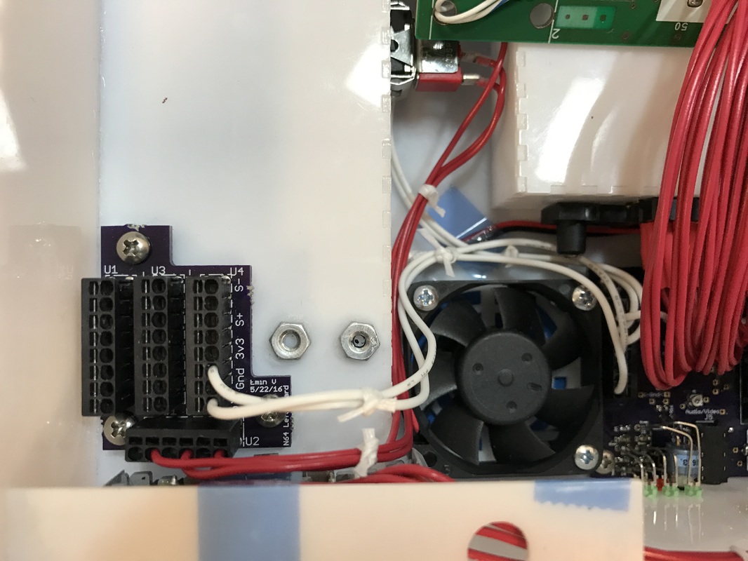
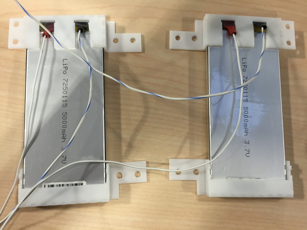
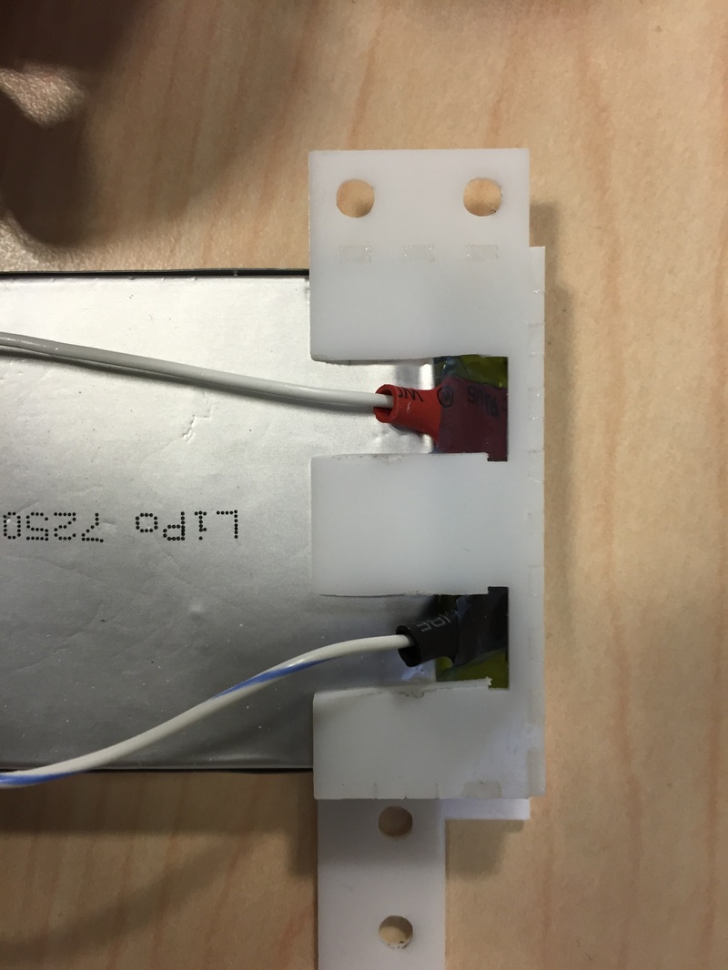
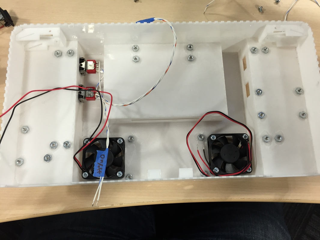
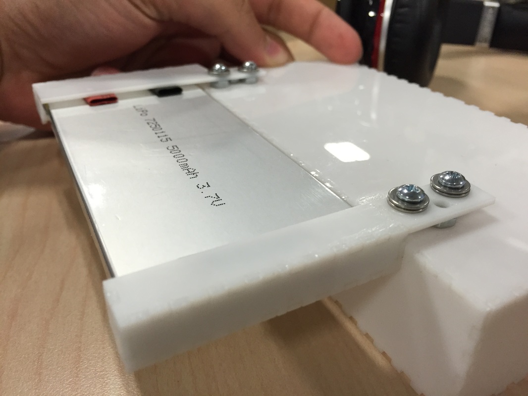
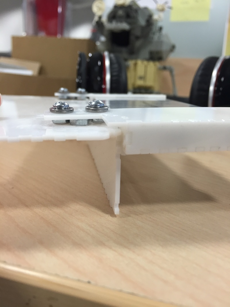
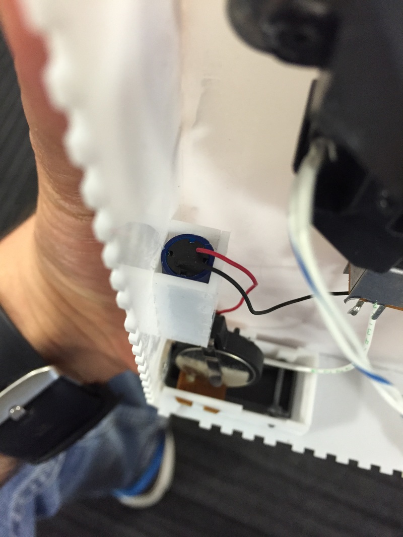
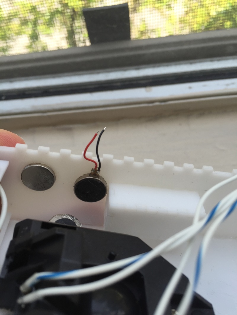
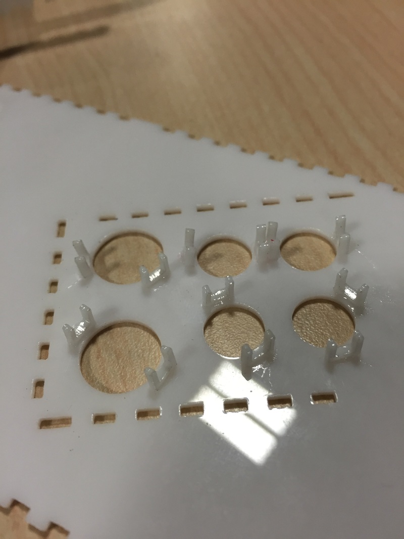
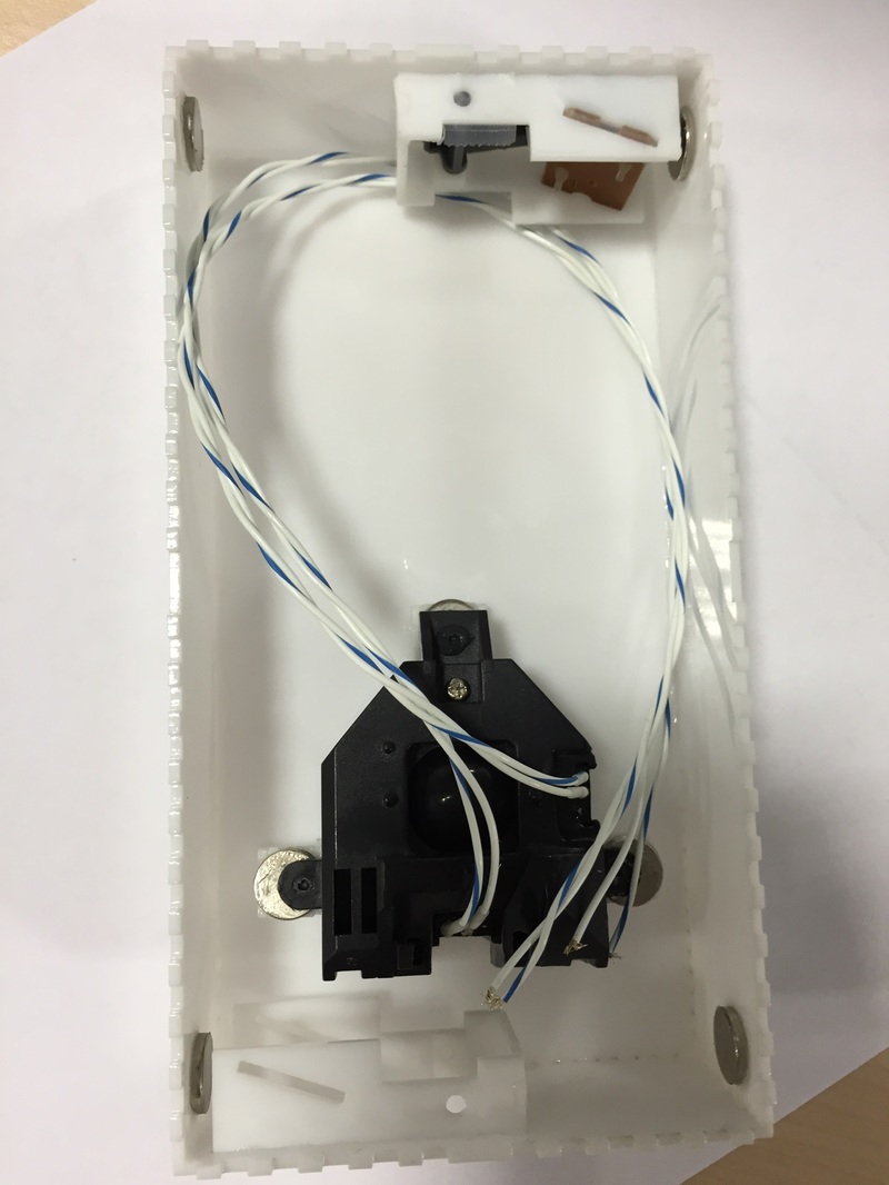
Box corners Small change to the box. Everyone who picked it up commented that shoulder buttons are hard to reach because of the harsh right angle edge of the box. So I set out to make a bevel. This pushes the button a bit more the the edge and makes the structure of the whole case less sound but feels so much better! Also looks really cool too. So the shoulder buttons and case area are settled. Battery Bracket Had to find a way to hold the batteries in place. It's hard to do since it's got no holes to put bolts through or anything. I re positioned them just under the N64 board so that I can put brackets around the top ends and anchored them to the inside of the bottom side of the case (see the picture). This allows the batteries to be taken out if they need to be replaced while allowing the bracketing to be moved out of the way so the N64 can be taken out. I used 3/16" 4-40 screws and nuts to hold the bracket down. With a couple washers as shims they held on really well! I just used the acrylic glue to hold the nuts down. I got all the nuts and screws from McMaster Carr. Vibration Motor + connectors I ordered the 28822 vibration motor from Digikey. and designed a little pocket for it on the inside of the test box. Turns out that thing is REALLY powerful and shakes out of its pocket so it rattles too much. You can see pictures of it inside the box being powered off a switch and 3V coin cell battery. I swapped the 28822 motor for a tiny button vibrator from digikey again. This guy was way nicer. No rattling and the current consumption is way smaller (I think like 50mA) plus it comes with a small sticky backing so I don't need a bracket for it. I also bought a connector which has push pin release from digikey. This will come in handy when I gotta build the PCB which takes all the controlls and wires coming from everywhere and distributes it to other places (since nothing is soldered down). Next Steps:
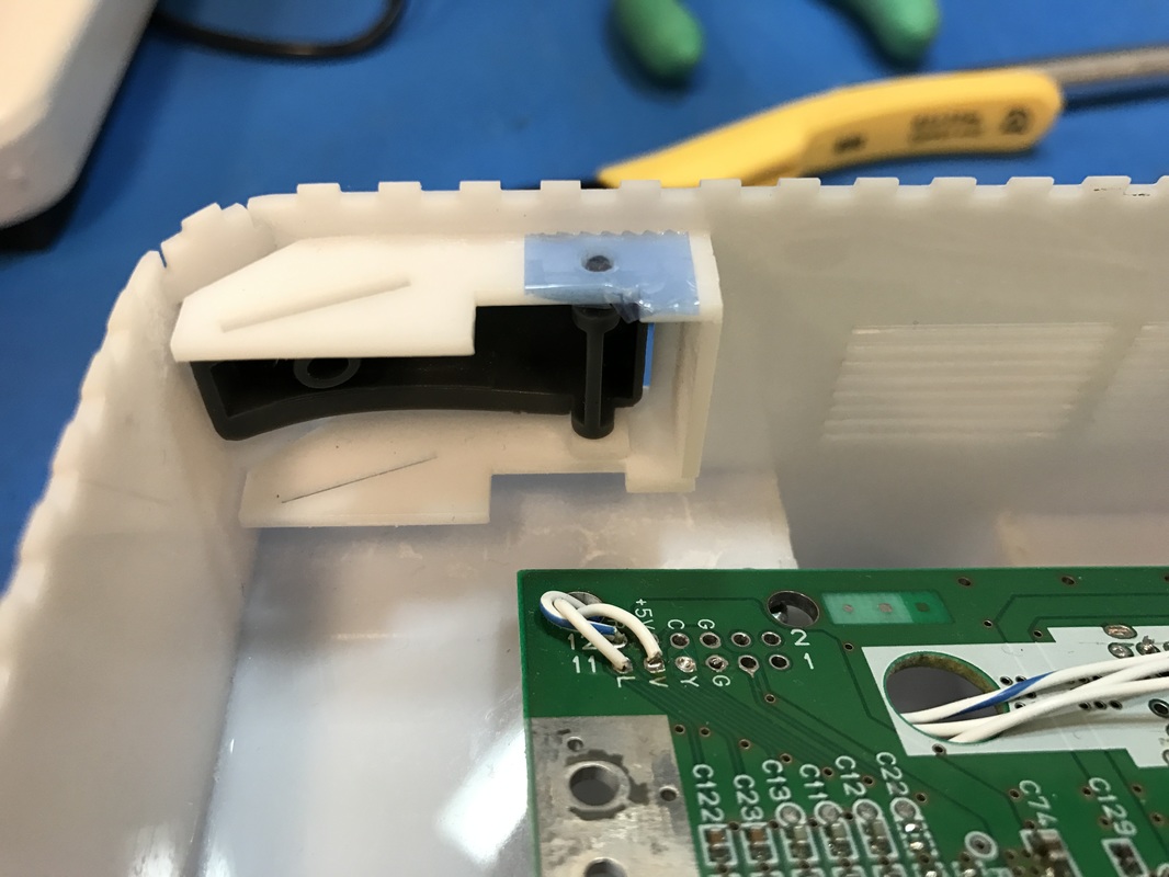
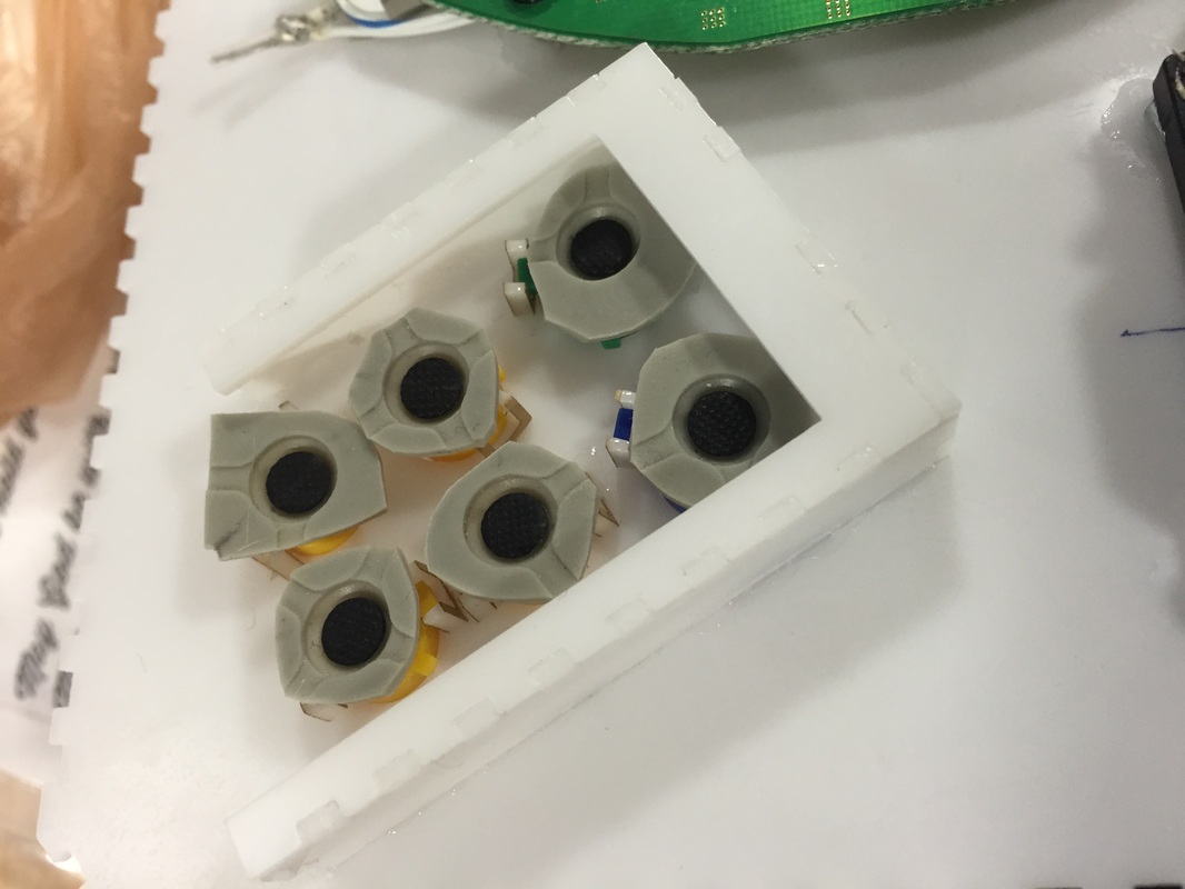
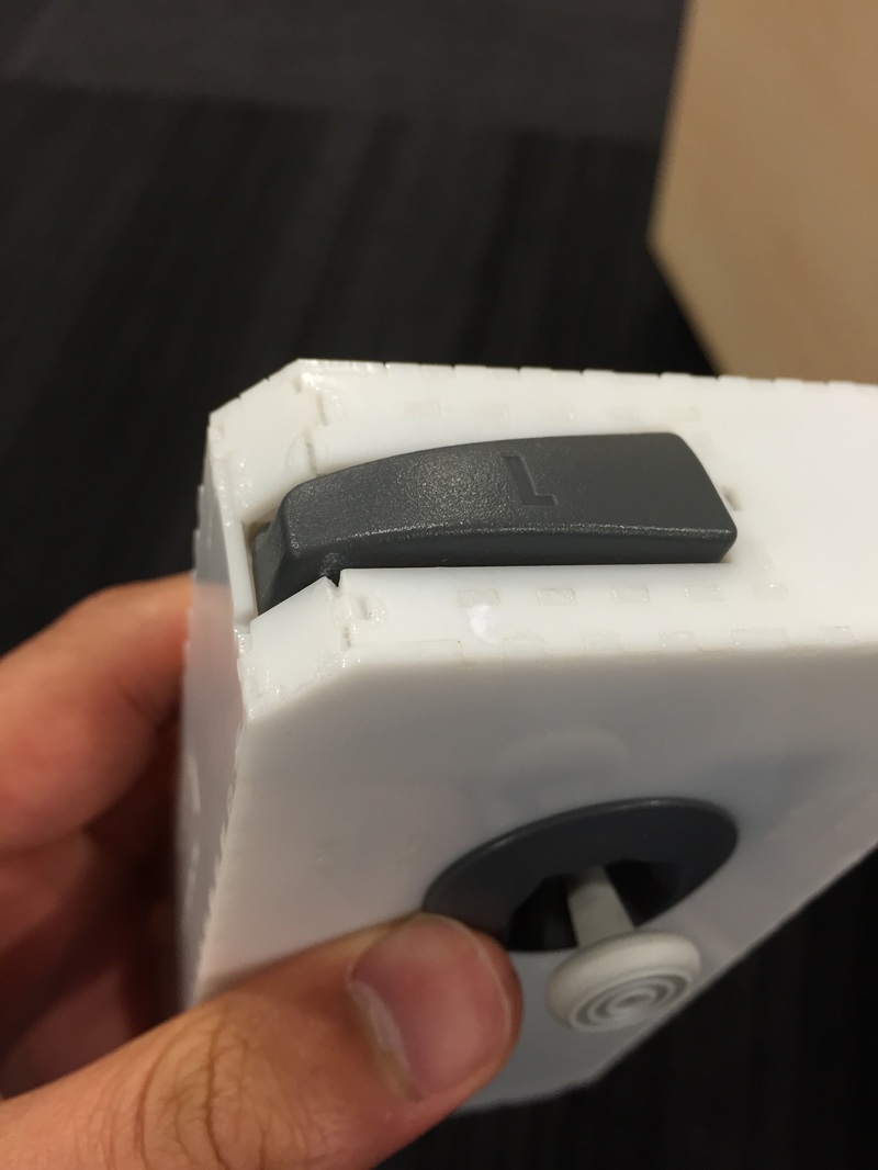
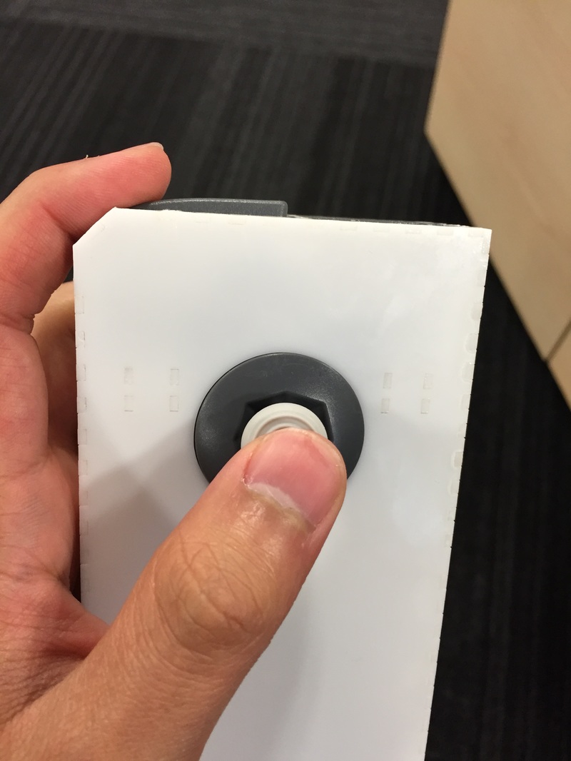
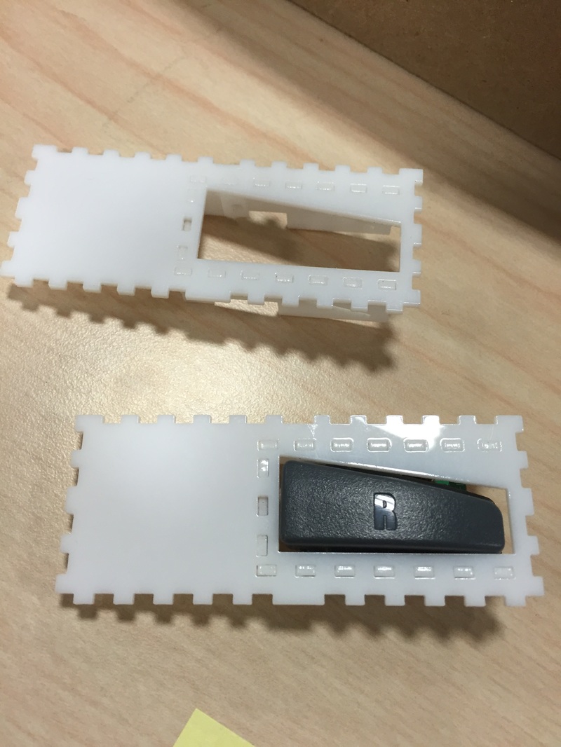
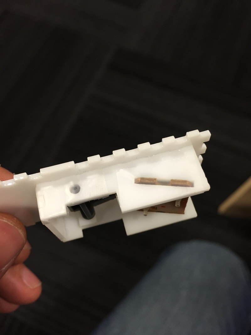
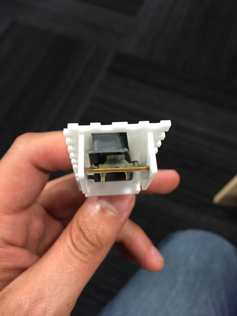
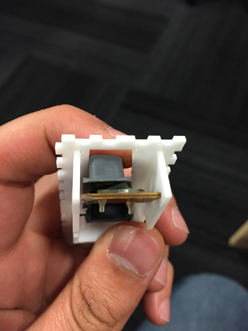
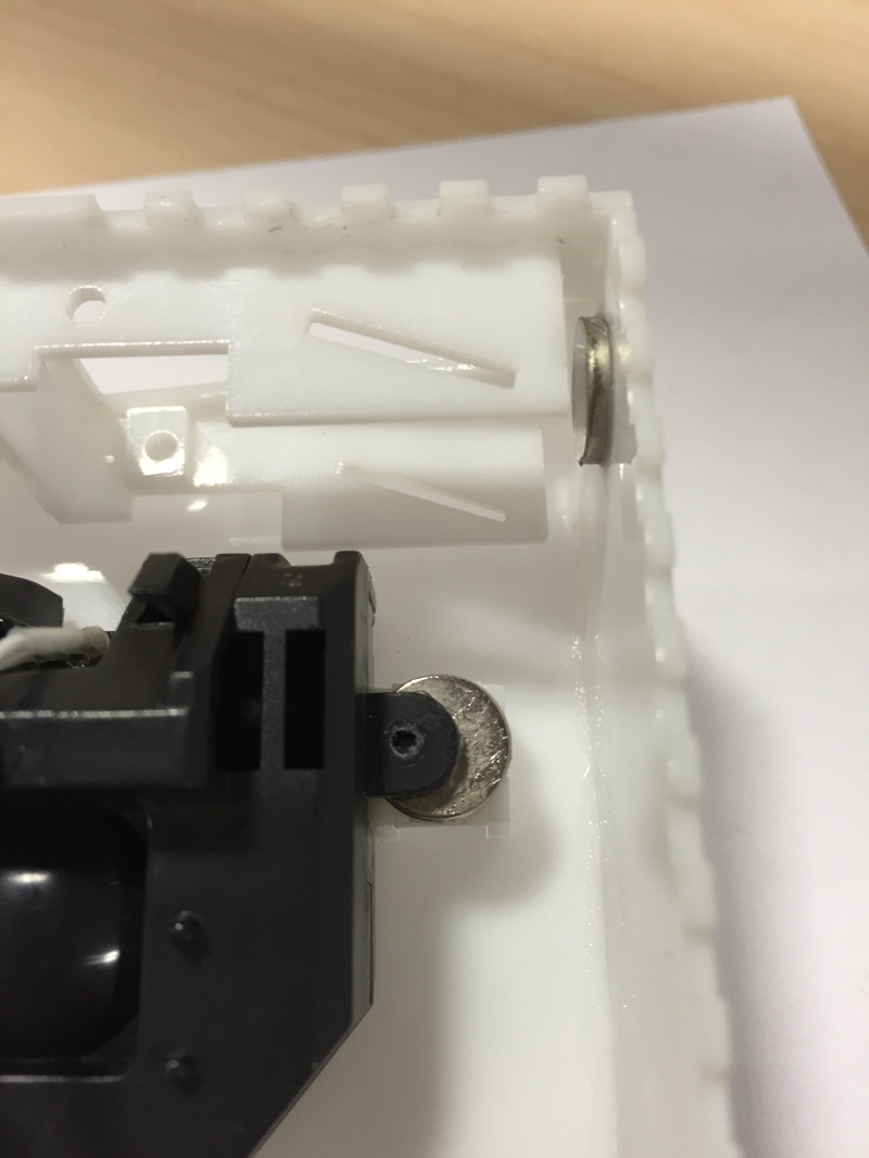
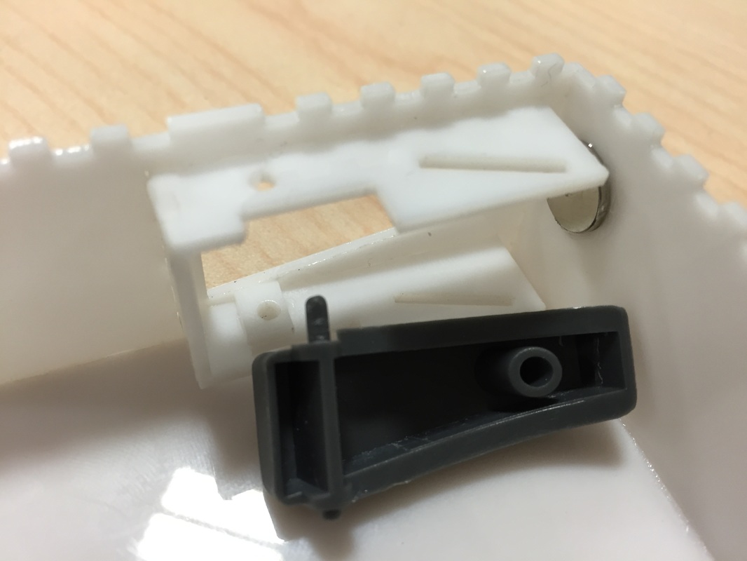
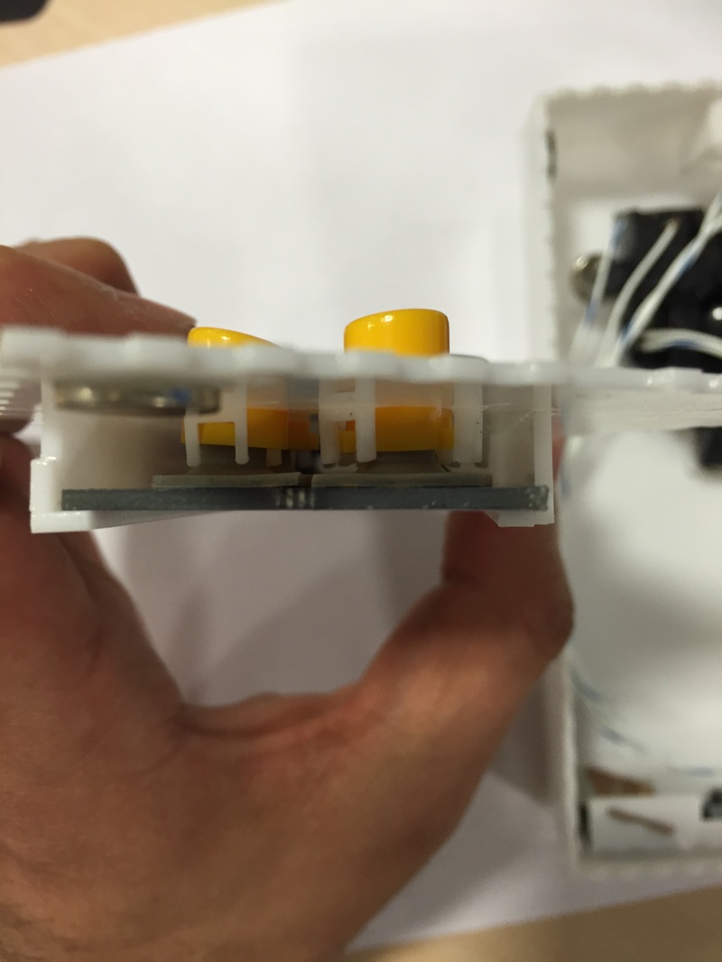
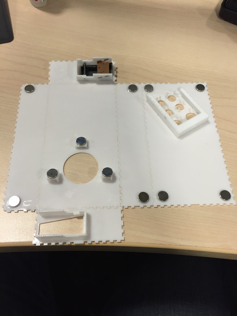
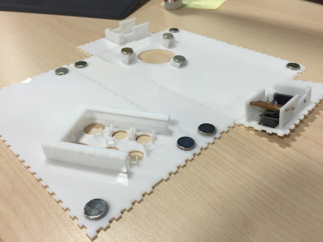
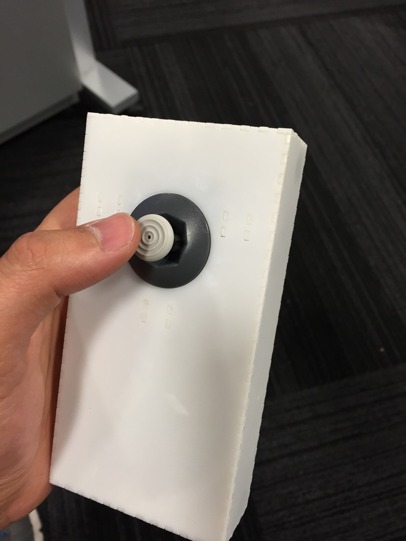
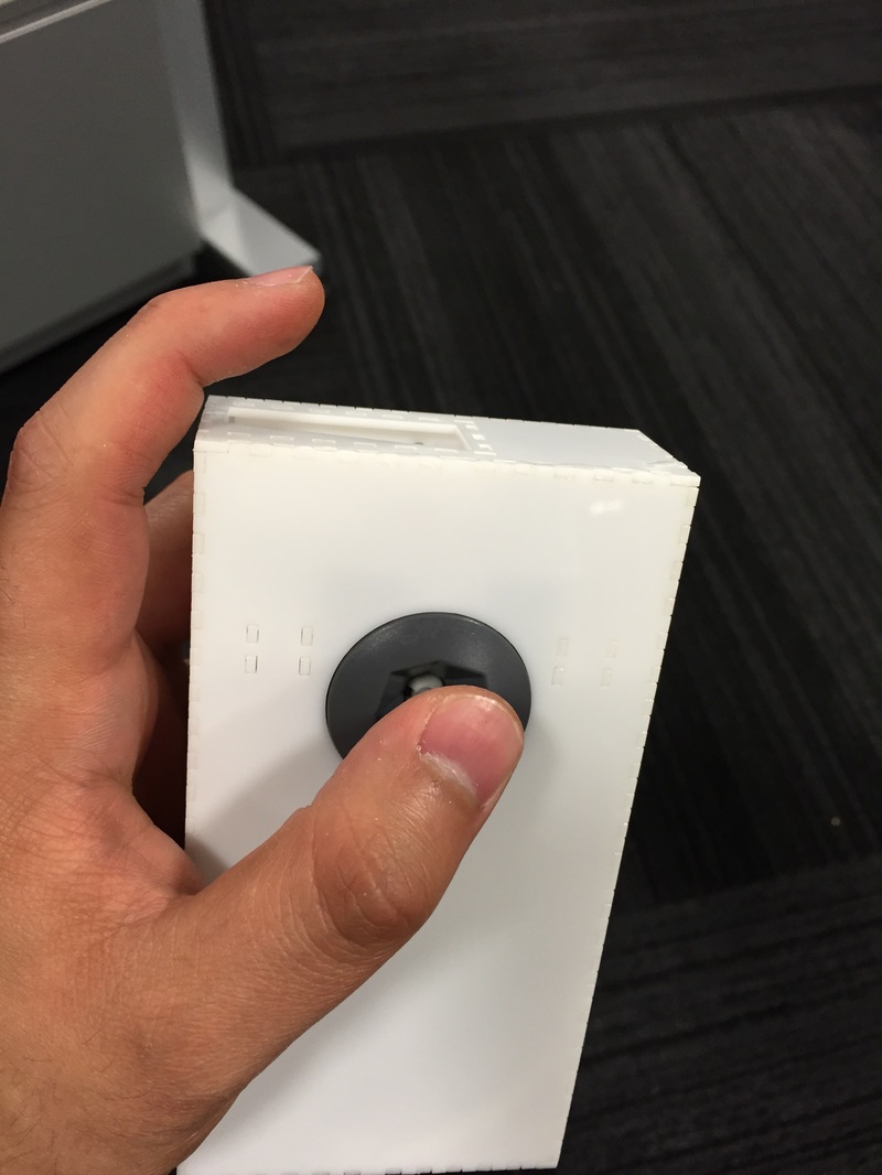
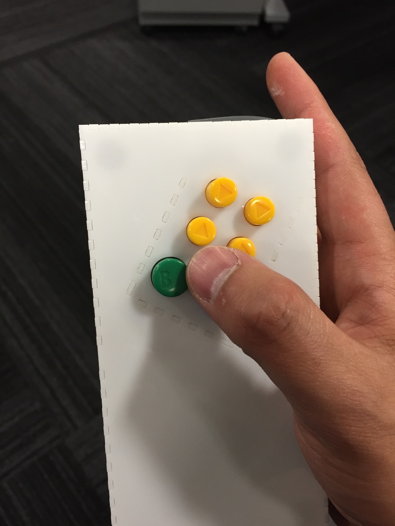
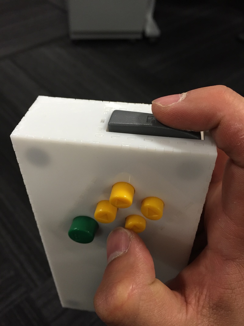
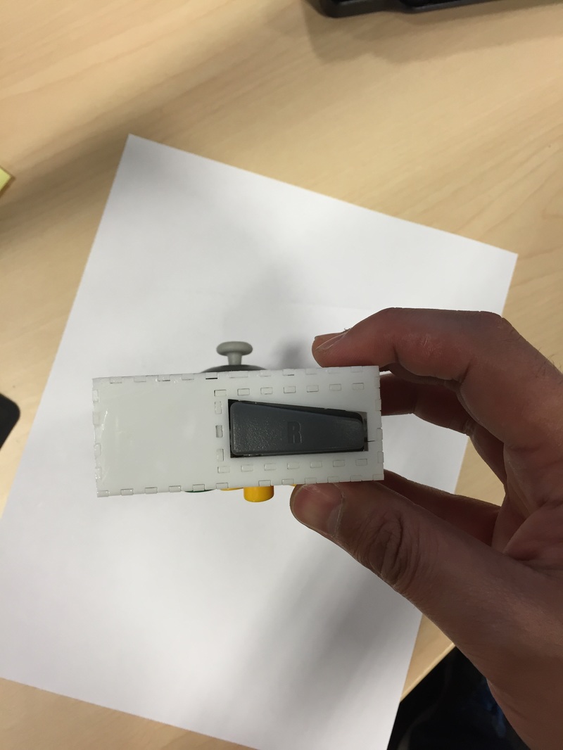
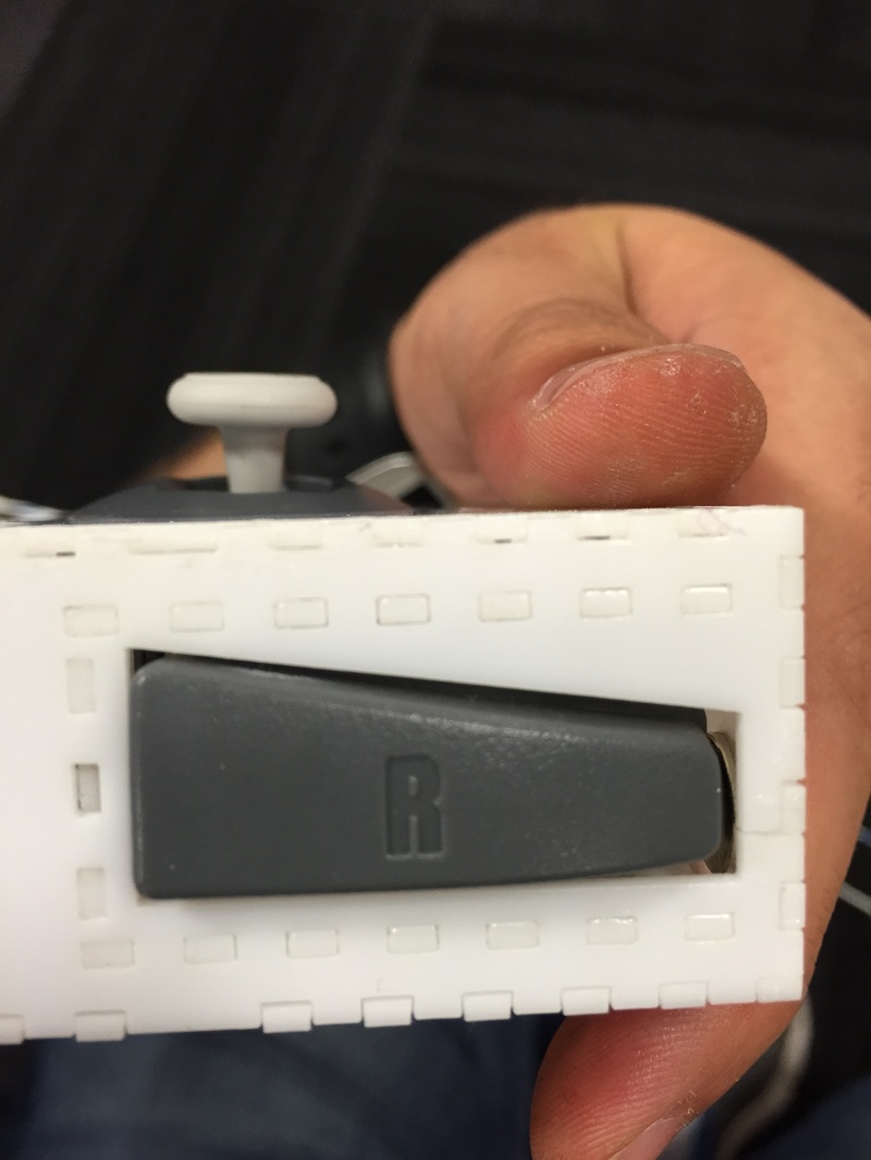
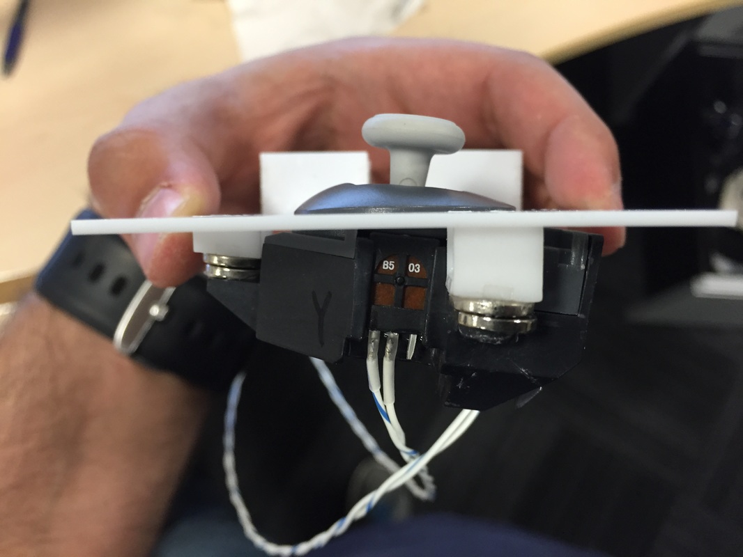
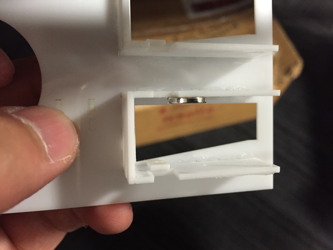
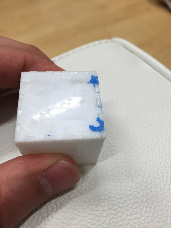
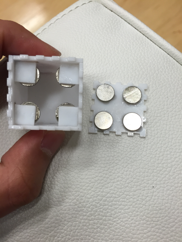
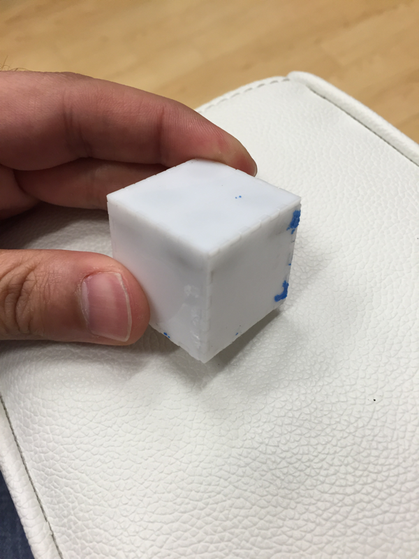
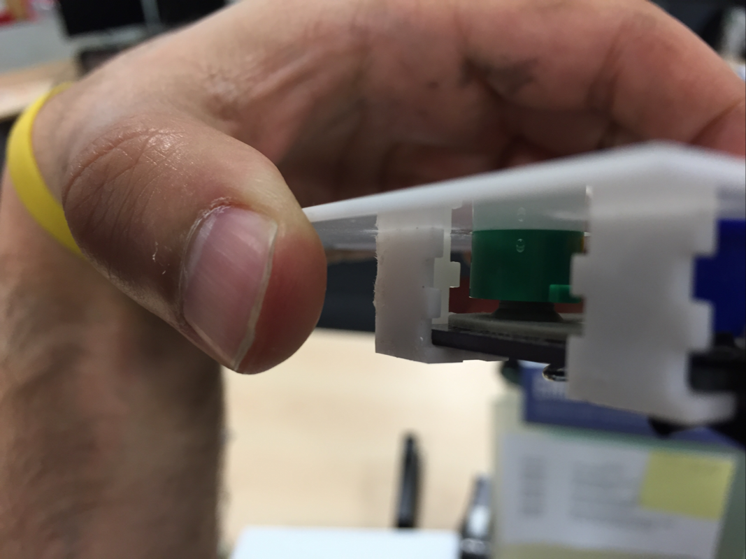
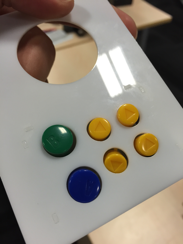
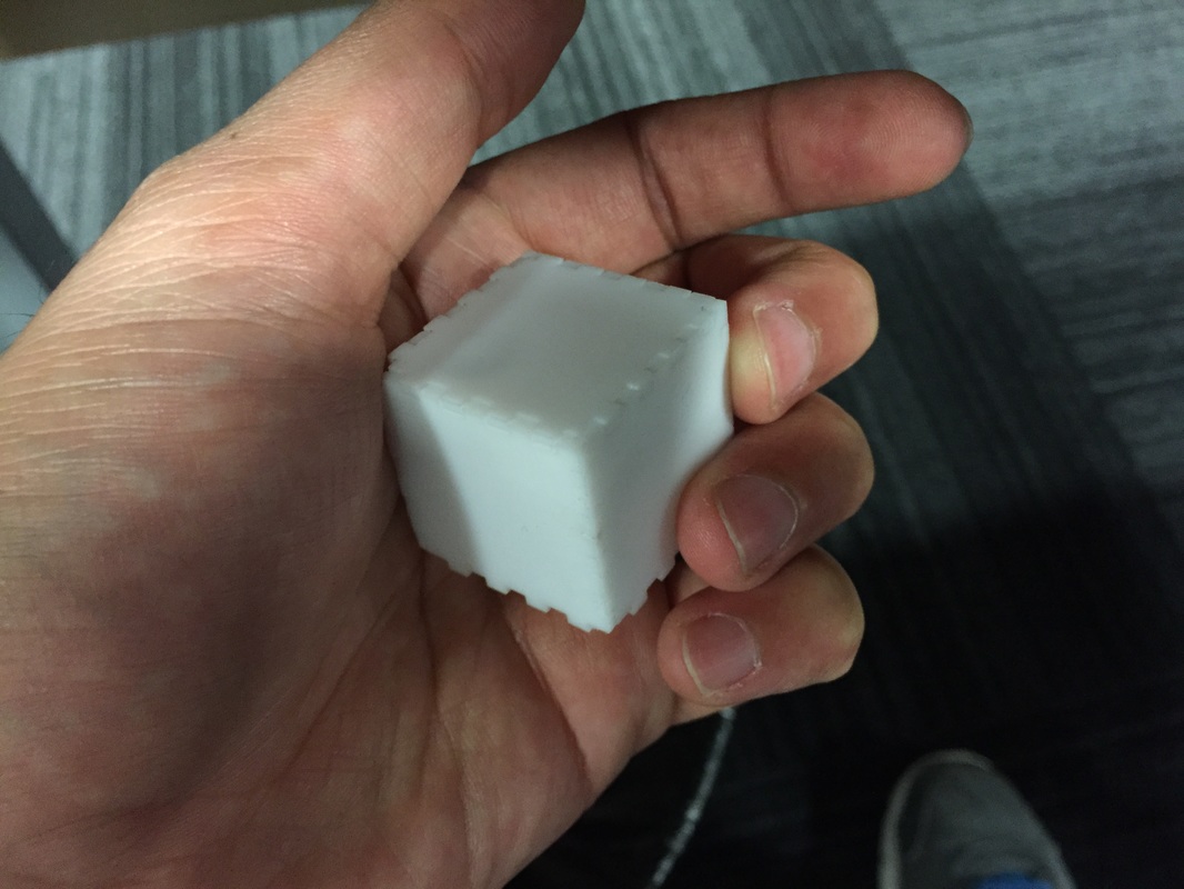
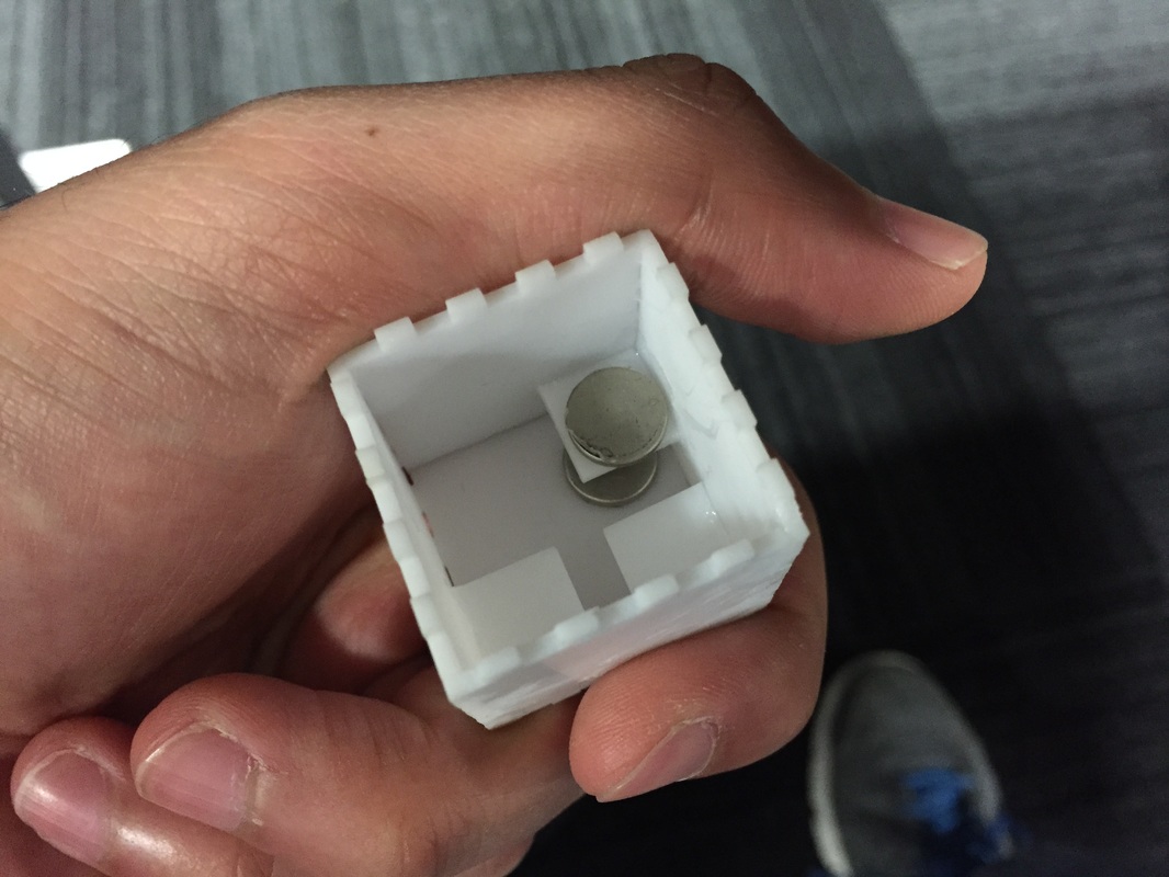
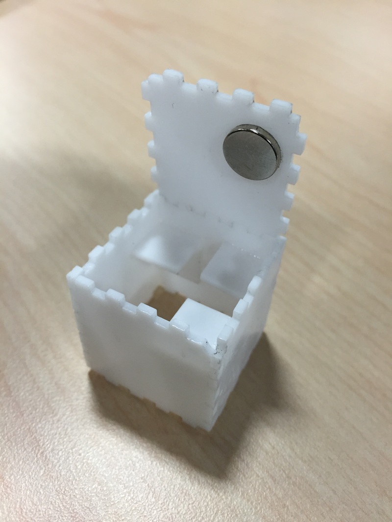
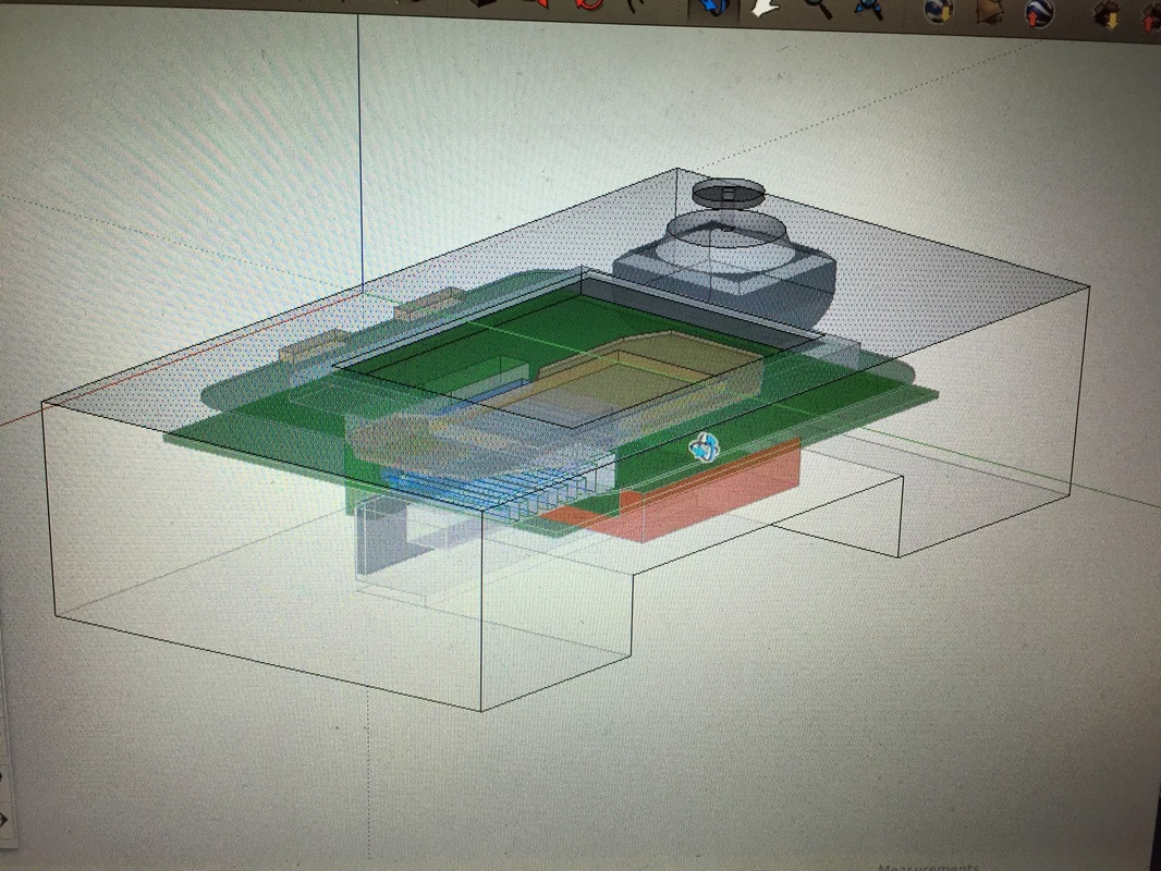
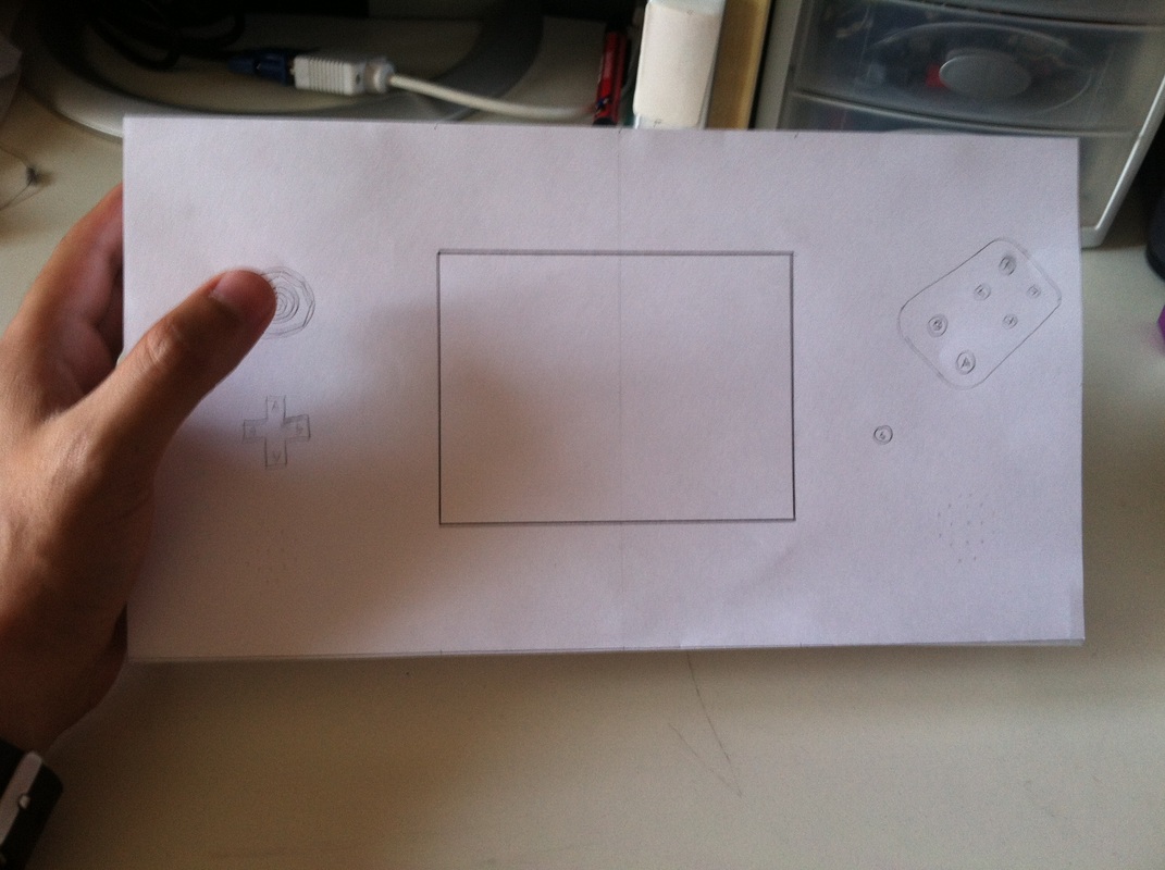
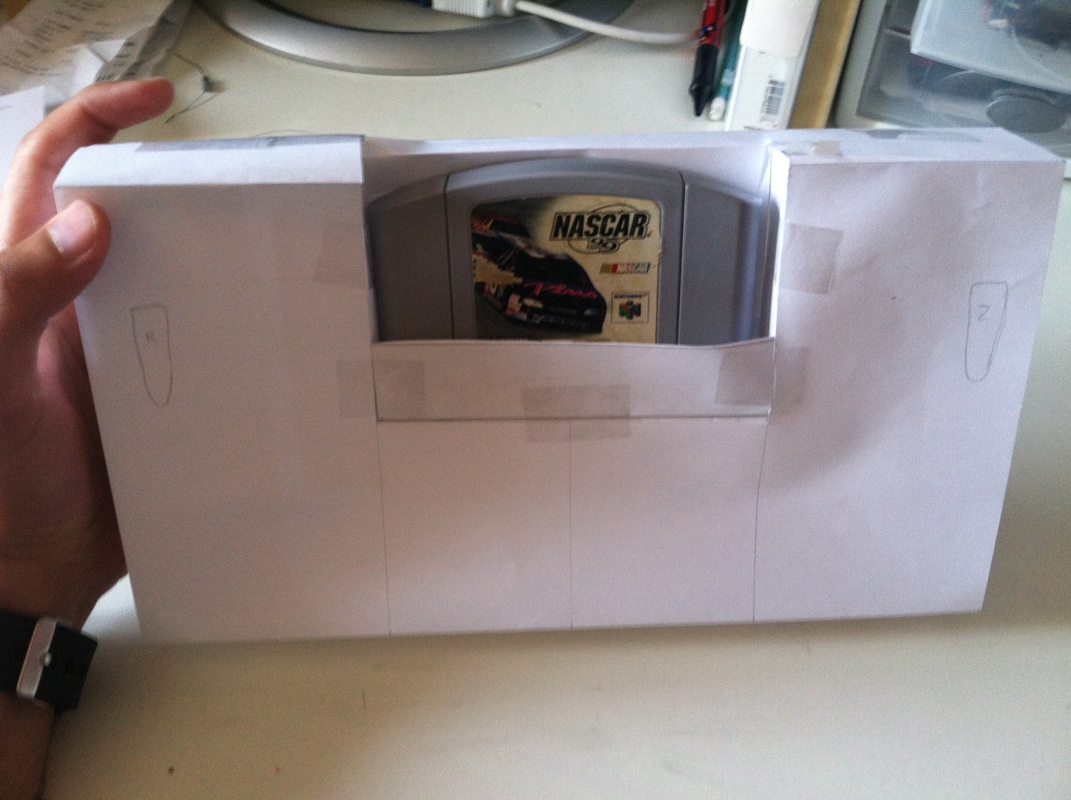
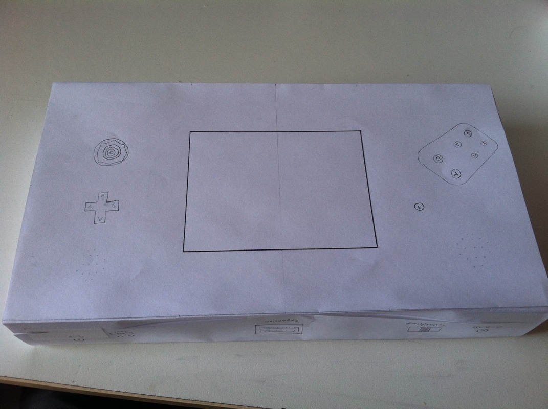
I gotta work a bit on the mounting of the screen. Once that's settled I can cut a complete face plate (including a place for the start button since that's never been done before). If that needs no revisions then I think I'll be ready to start cutting the bottom most pieces of the final case and start integrating stuff into it. Very exciting! Shoulder Button Redo Had to redo the shoulder button, making one side of the bracket holding the actual button pcb a tight fit and the other side a wider fit so I can sneak in the PCB after the fact. Have to use a piece of tape to keep it from playing around too much but I think I'm happy with that. It doesn't take too much effort for the tape and its small enough. The pivot point bracket was slimmed down as well. As you'll see in the sketchup model the bracket for the ABC buttons was encroaching on the space of the shoulder button bracket. A tiny piece of tape keeps the pivot dowel from rattling too much as well. I also made the opening for the button a bit slimmer. I'm very happy with it. Made a mistake and cut the same panel out for L and R buttons so the L button wouldn't work for this demo, but I swapped the R button around for pictures since its all made to be serviceable. Also you can see there is a tiny magnet next to where this guy mounts, this is to that the box closes and stays shut. Refer to an earlier post where I made a simple box with magnets. I brought to button about 3mm away from the edge of the box so my index finger wouldn't have to reach as much. ABC Buttons I had to make one side of the bracket shorter this time around so that I can push the buttons as close to the top edge as possible without hitting the shoulder button assembly. I also got a bit too cocky with the little alignment pegs and messed up a few places. But all in all it's just like the last design. Box I wanted to make a box that would allow me to hold each side of the controls (ABC and R button, Analog stick and L button) to get a feel for how far away from the edge I could put each assembly while keeping it comfortable for me to hold in my hand. Bot Analog stick and ABC buttons are centered about 37mm from their respective side edges which gave me a comfortable grip so I wouldn't have to reach to hit the B or C buttons and I could move the stick all the way to the right easily. I wanted to keep both controls at about 40mm from the top but the ABC buttons' bracket was getting too close to the shoulder button bracket so the analog stick is centered at 40mm from the top but the ABC buttons are about 45mm (ABC button assembly's middle I'm taking to be a bit higher and to the left of the A button. The rest of the box is pretty simple. The face-plate is held on by magnets. The analog stick is held on by magnets as well just like my last post. I made the box's depth 30mm from outside top face to bottom face. This gave the inside ~27mm which was just enough for the analog stick (I think its like 26mm at its lowest, hard to measure since its on a slant). I miscalculated a little for the panels that hold the shoulder buttons, they are a bit too short so you can see they cracked in a couple places when I glued that piece in. Not a problem though, just gotta be careful on the final cut. Conclusion The grip feels great. I was worried at first when I only held one side and tried to articulate the stick and press the shoulder button as well, since that's going to be the Z button for most of the time I wanted it to feel comfortable. After realizing that I'll be holding the whole console with two hands and that there will be force from my right hand helping me hold the thing my left index finger was a lot happier in pressing the shoulder button.
Next Steps:
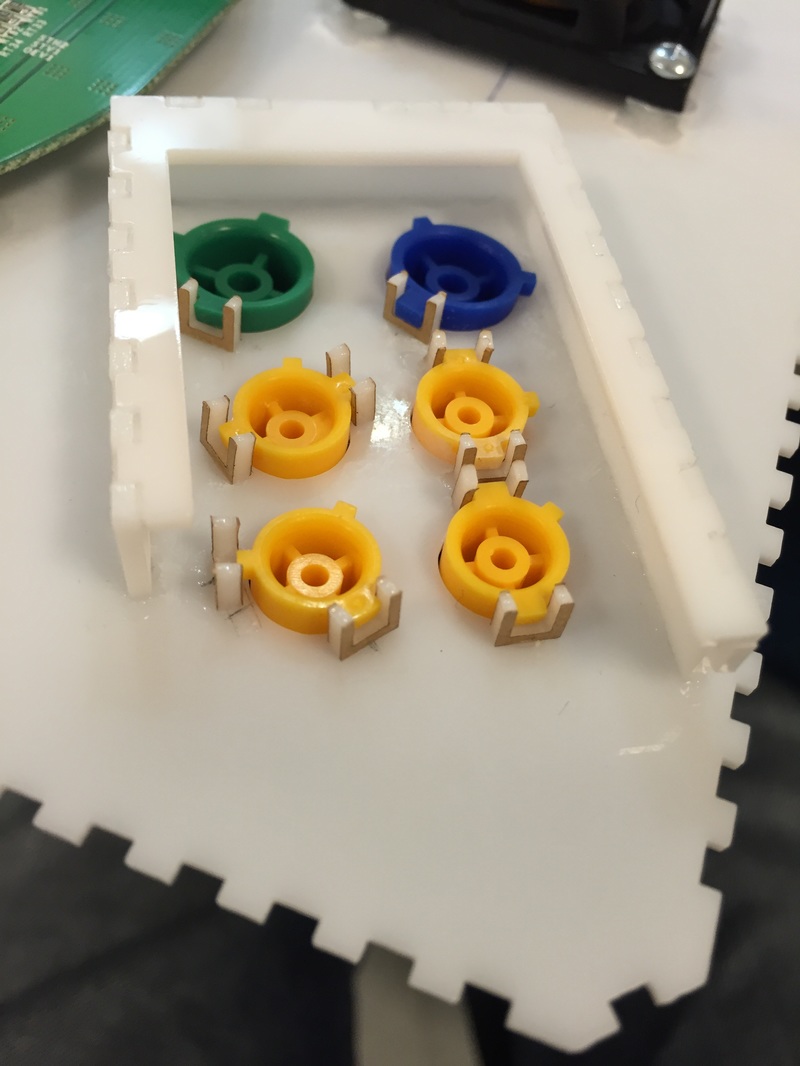
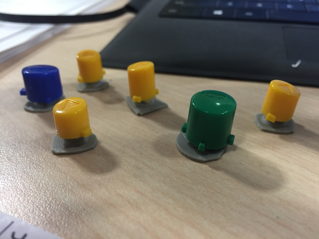
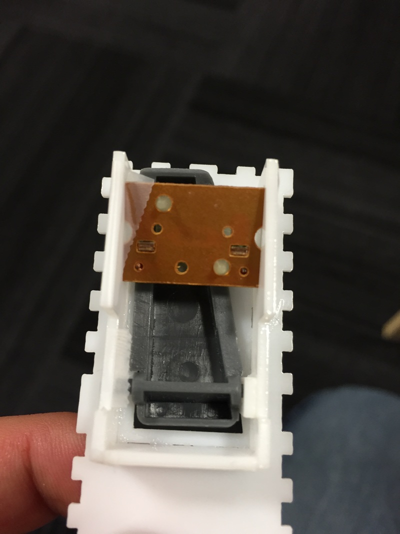
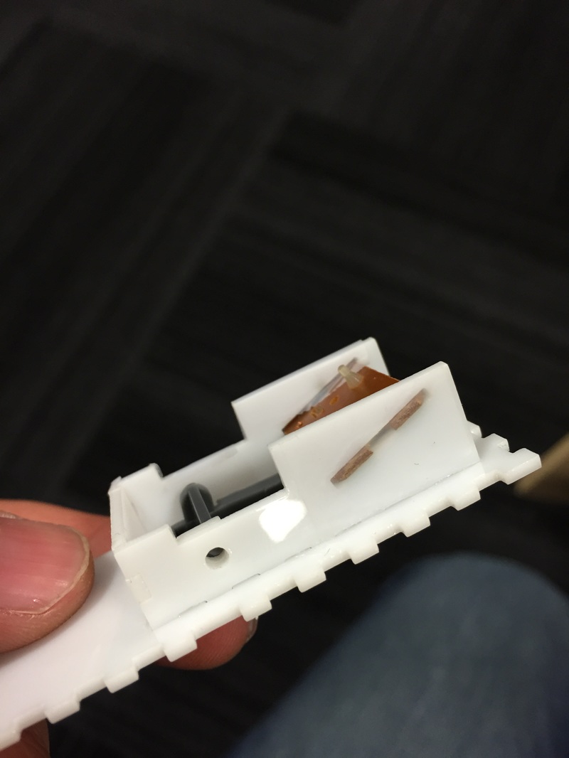
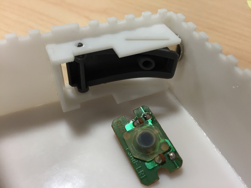
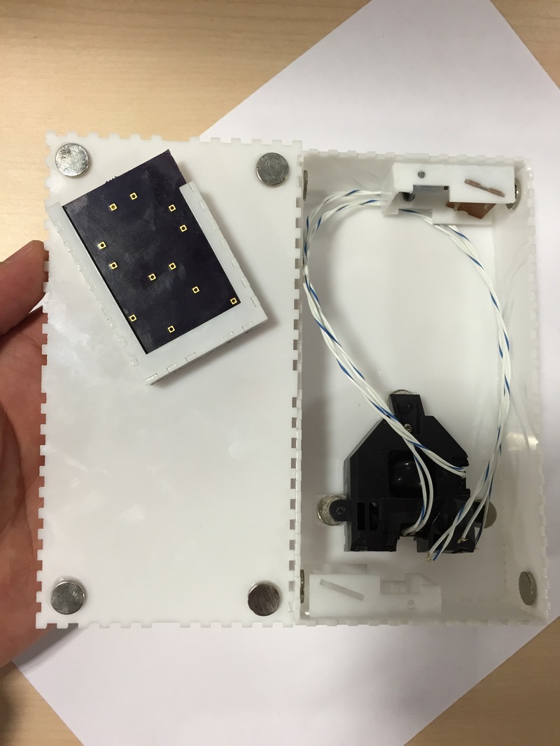
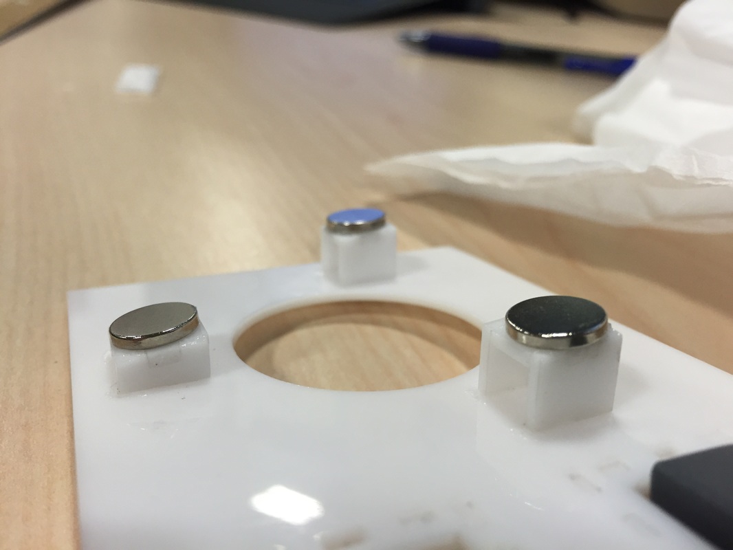
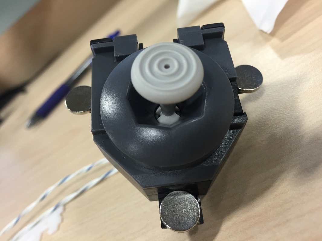
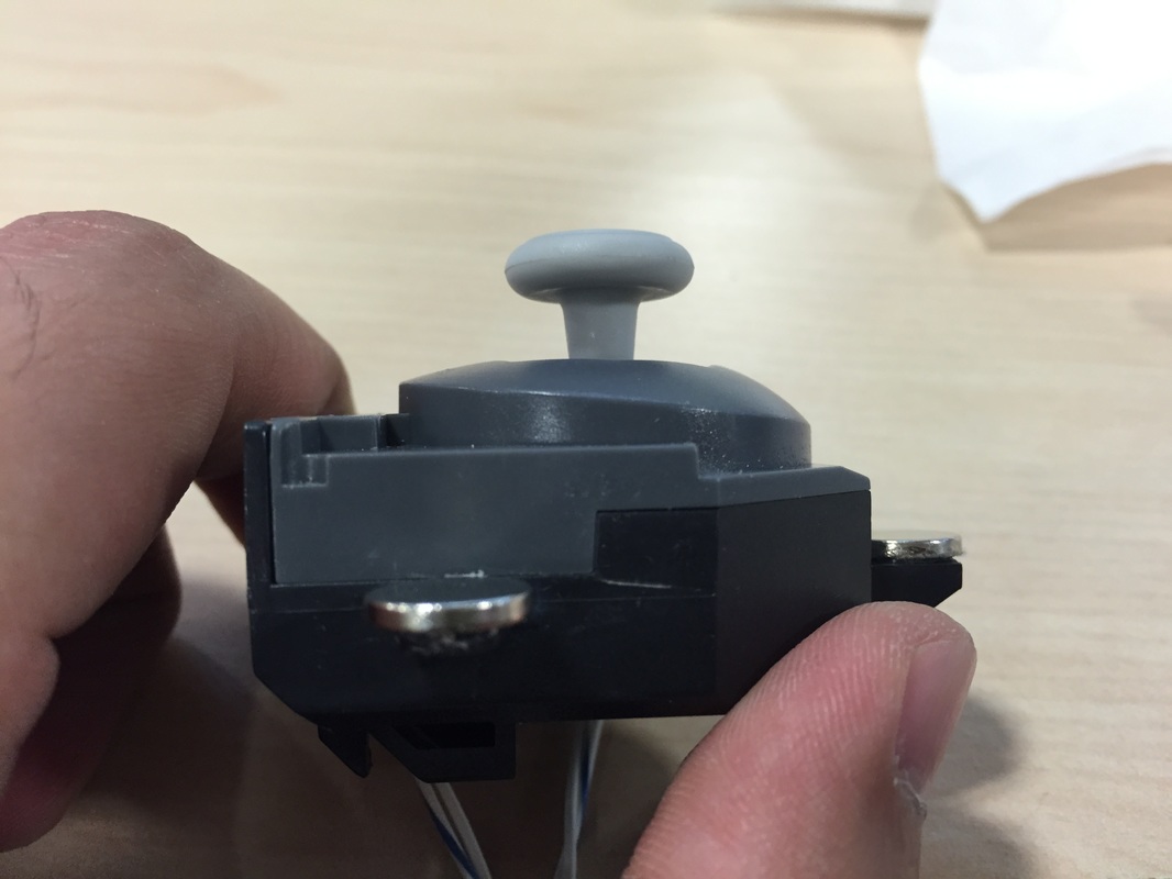
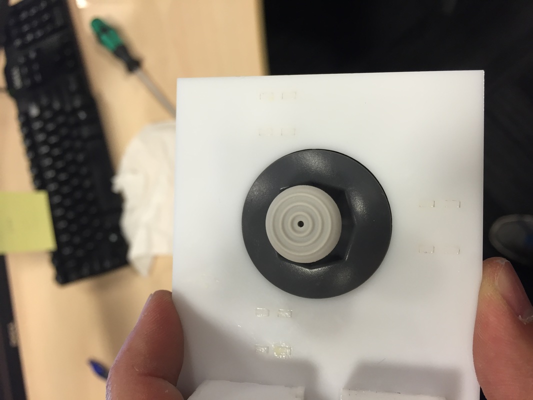
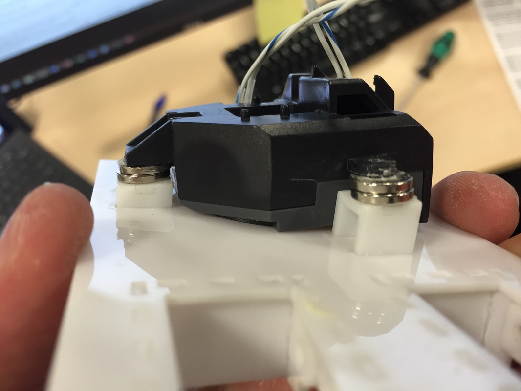
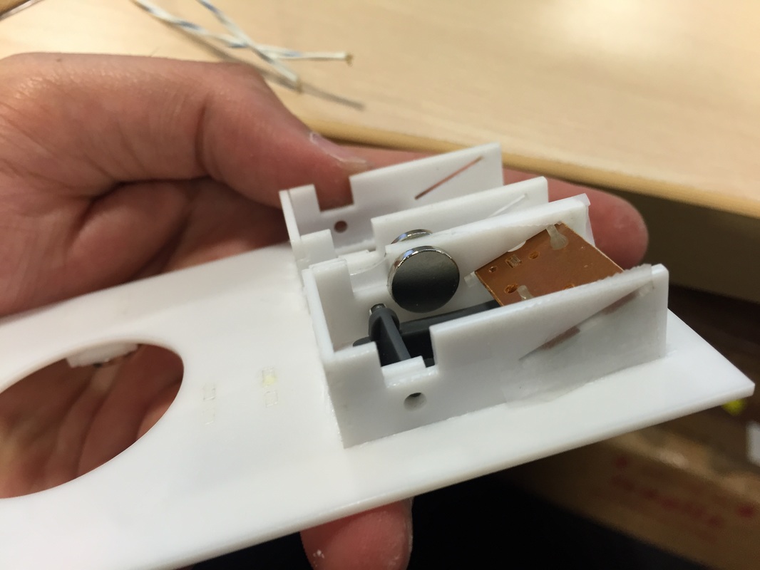
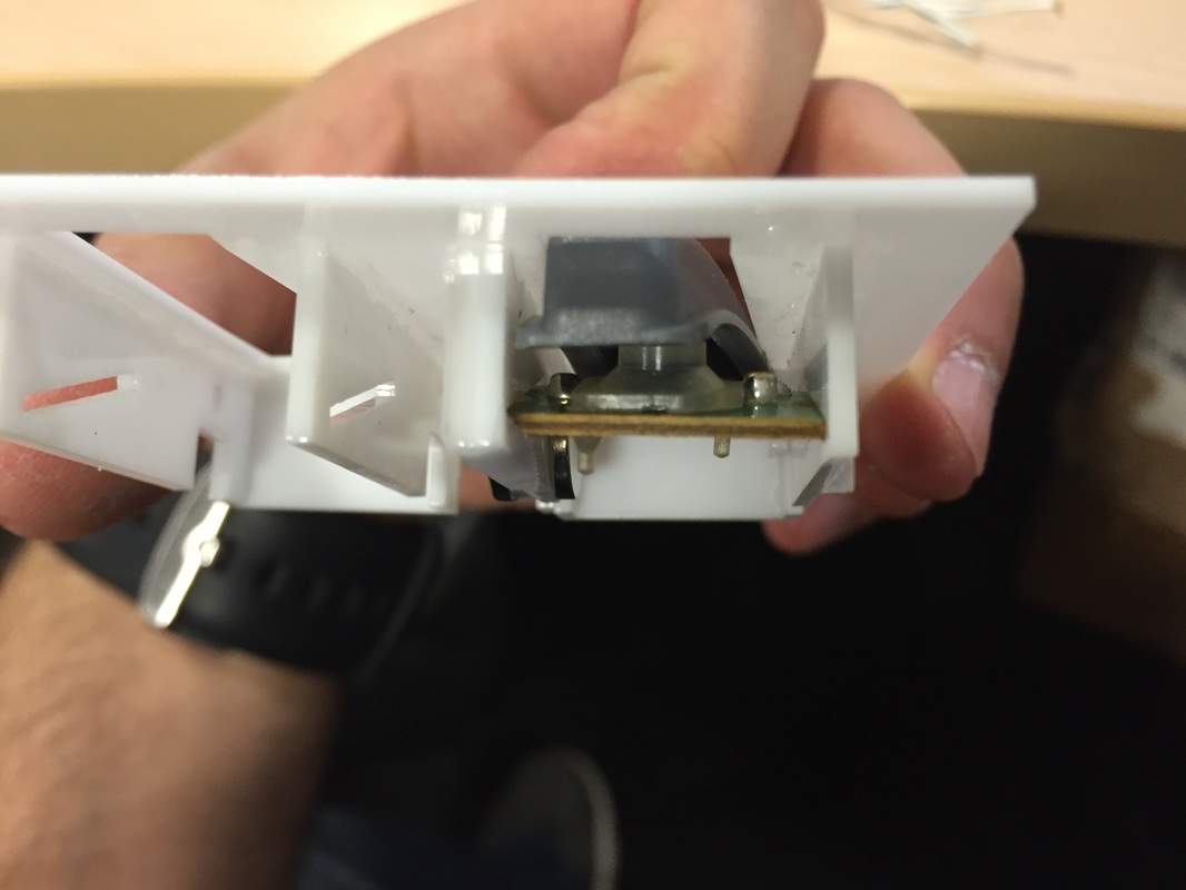
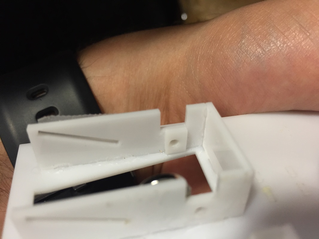
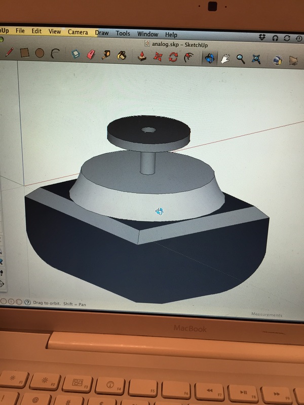
I'll be worrying about the screen assembly next. I've got a less-than-optimal bracketing system set up but not sure if it'll hold up, so gotta run a test of that. I'm trying to etch away a certain depth of the acrylic sheet so the screen has an indentation to sit in. If that doesn't work then I'm thinking an extra layer of acrylic added to the border of the cut-out to hold a bit more of the screen. Gotta think it thru more. This will affect the overall model of the box which I gotta update since all the controls have been finalized. So it's back to imagination and sketchup! A,B and C buttons I'm getting pretty good at designing brackets now days. I iterated on the last revision by making the shelf shallower and adding pegs to keep the buttons from rotating. Also had a go at designing the R button and analog stick brackets but they didn't pan out in this one so had to separate them. What's really nice about this ABC button design is that its completely serviceable, everything can be taken out, including the buttons, for replacement. See the end of this post for Google Sketchup models. Analog Stick The analog stick gave me a lot of anxiety because it frequently breaks or becomes loose and its bracketing was going to be tough as it is slightly angled. As you can see in the pictures, the top dome base is slightly (6.5 degrees) inclined relative to the body and brackets. After a lot of headaches I settled on holding things with magnets. I made angled posts that came down on top of the mounting spots on the analog stick and glued the same circular magnets as before. This thing is one sturdy mofo! Gonna be tough to get it apart, which is nice because the analog stick gets pushed down and around a lot, so you want it to be strong. And if (when) the stick breaks, I can swap in a new one no problem. Shoulder Buttons After figuring out the analog stick, I realized that mounting the L/Z and R buttons underneath the unit was gonna make it too thick to hold comfortably. The Analog stick alone sticks down like 28mm so an extra mounting bracket for the trigger would make the analog stick side uncomfortable to hold (especially while you have to hold down the Z button while still maneuvering the analog stick in games like mario kart). So It's gonna have to go on the top like the original shoulder buttons, the L and Z functions sharing a button of course. My first try at a bracket for this failed, the opening wasn't big enough and the button could not be taken in and out without breaking the thing. My fix was to move the side walls apart a bit and add a little extra material to the short side of the button's pivot dwell. That things gotta be small enough to let the button be installed but big enough not to let the thing fall out. Next I focused on the circuit board with the plunger on it and how to get that held in place. I love the idea of the slots on the side but they gotta be tight so the board wont come loose and fall out. I tried two iterations of it side by side one with wide holes and the other with holes to fit the PCB exactly. The tight one was a no-go since I couldn't get the PCB in in the first place. The wide option was doable but the slits were to big and the button wouldn't stay in place. So I made a copy of the tight one, cut the dove tails off of it and stuck it to the side of the wide one with two magnets (can you tell I love magnets?). This lets me take the tight one off, position the PCB under the button in the wide slits then bring in the tight slit again and sorta lock it in place. I had to use a small piece of tape to not let the PCB move too much but it worked fine and the button pressed well. I'm gonna try to make it better in a last (hopefully) iteration where I have one tight side and one wide side which gets tightened with the snap in piece. We'll see... Sketchup Models Check out the google sketchup models for dimensions and details. Next step will be to design the R button bracket a bit better, make a small bracket for the start button, then make a box with all the controls jammed into one so I can see if the placement of the controls relative to the edge is comfortable or not. Stay tuned....
PS. All this took A LOT of planning and trial/error. Numerous times I wanted to quit or put it off until later. If you feel like that then don't give up, you're on the right track, and I hope this guide is helping.
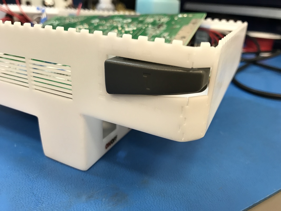
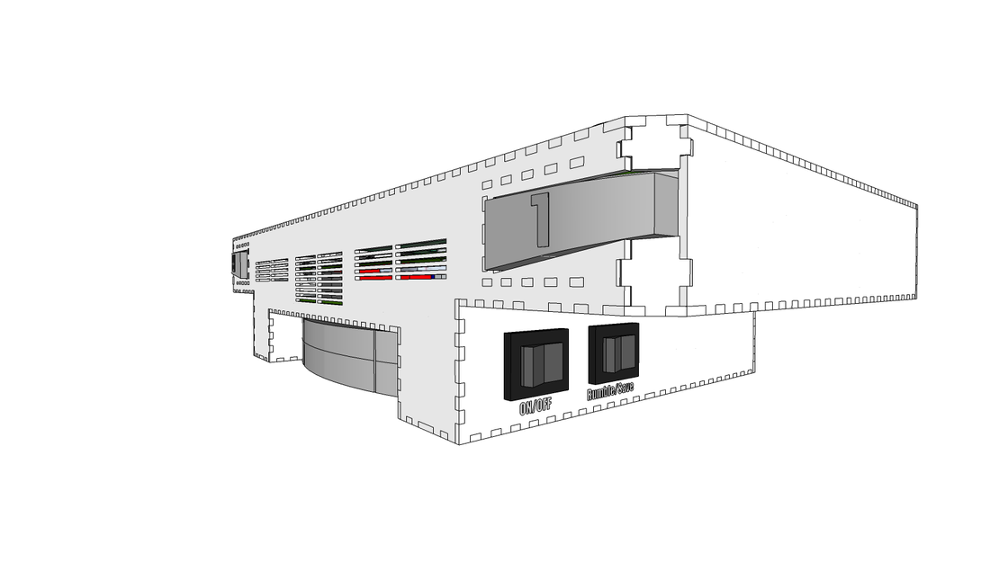
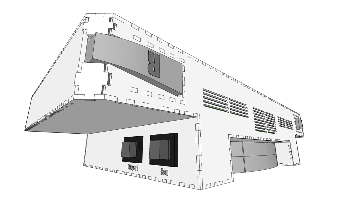
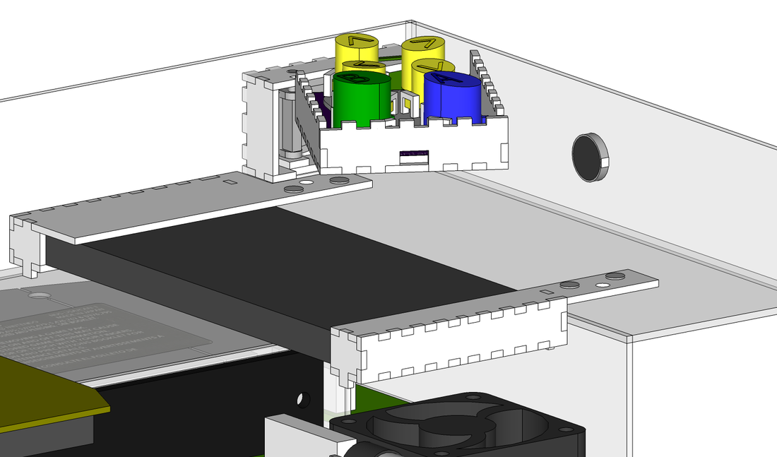
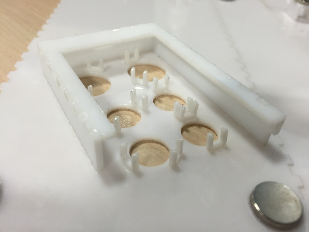
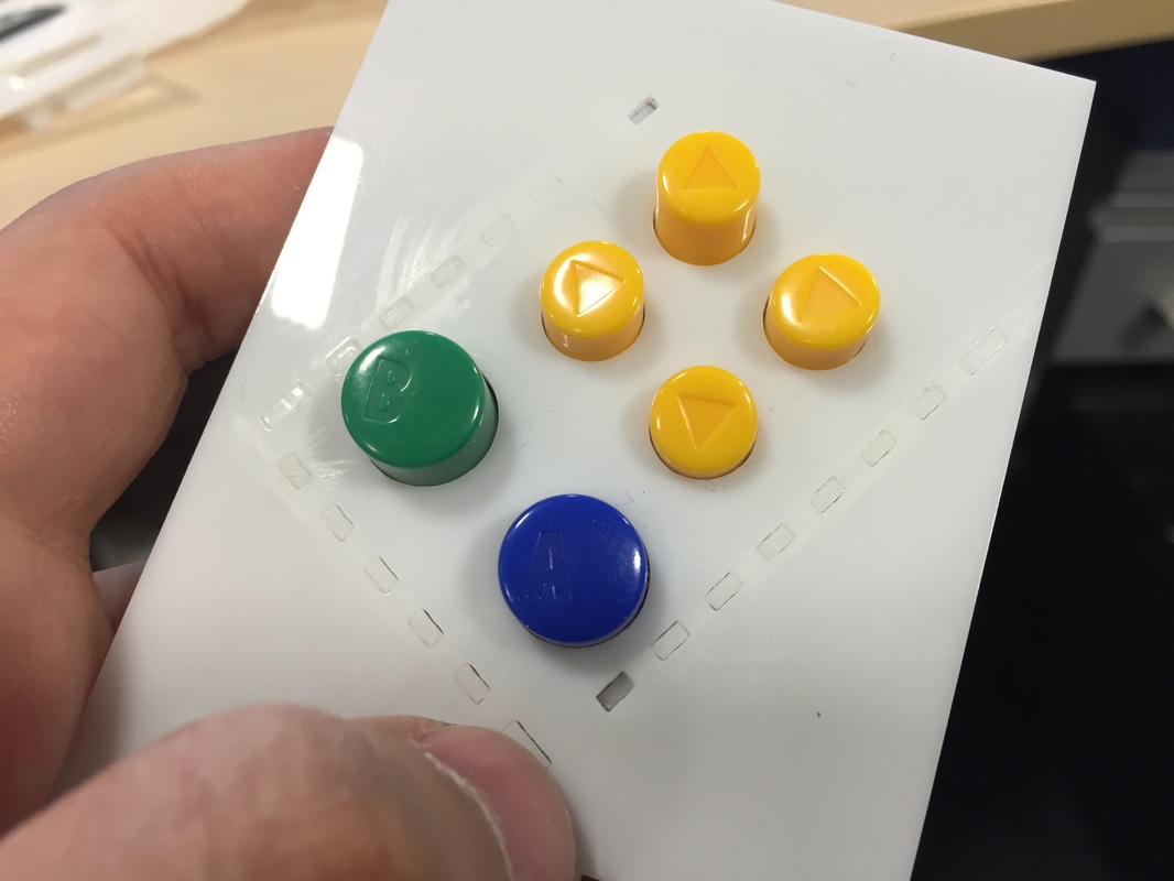
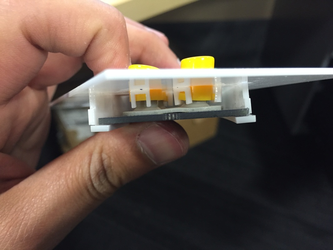
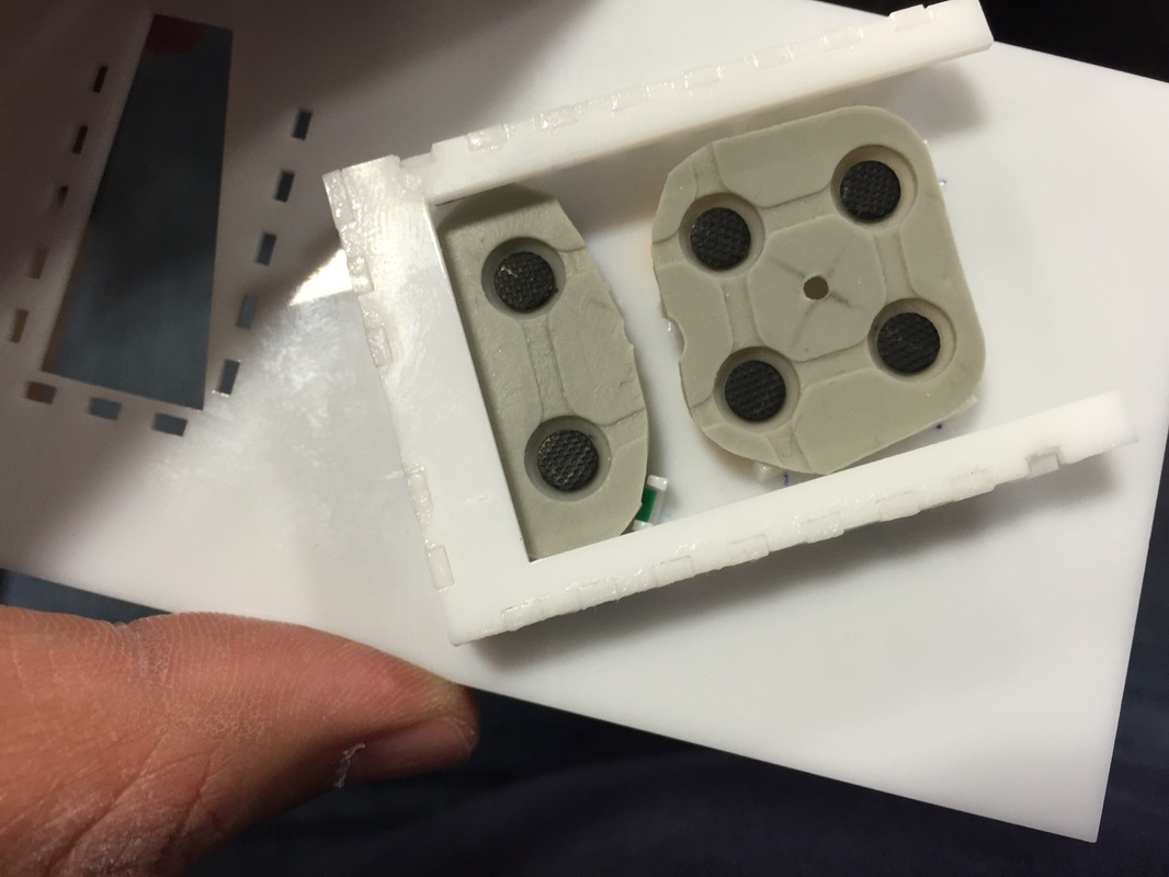
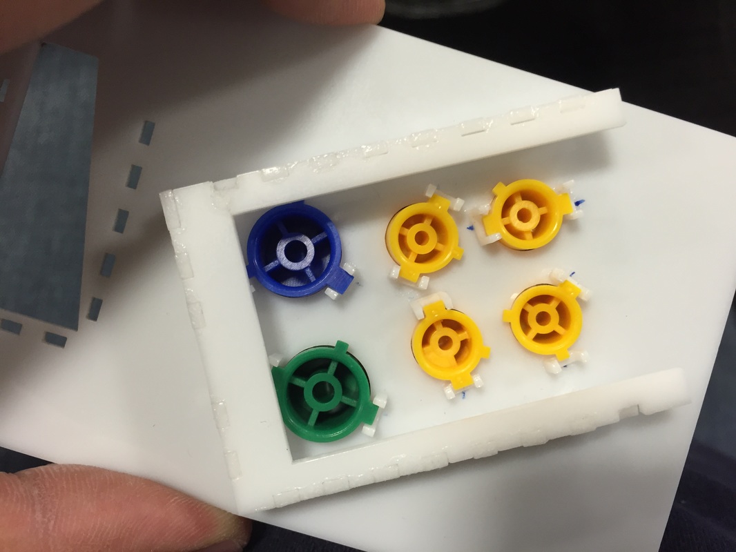
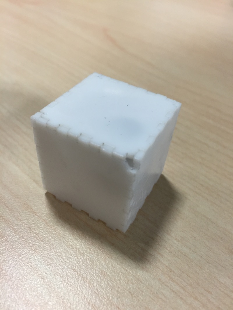
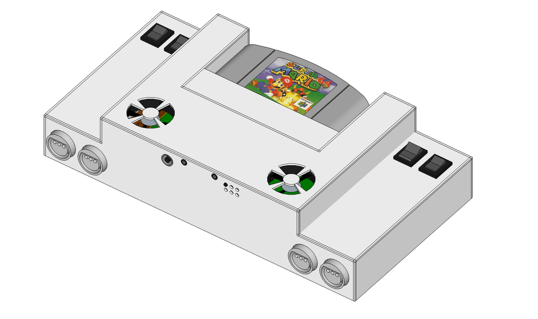
Box Trials I built two more boxes and fitted them with magnets. Getting better and vizualizing the shapes of the puzzle pieces fitting together in 3D. Also getting better at glueing. Started off using too much glue which scuffed (read that as burned) the surface of the acrylic since this glue technically melts the teo pieces together. Even had a piece of my latex glove stuck on there once, nasty stuff. But after all that I think I've gotten to a box that is easily openable from the top. I also made a second box i didnt take pictures of which had the box side magnets glued to the sides of the walls near a corner. Less force holding the lid down but that one was easier to build since theres not platform. We'll see on the fullscale model what the lid needs. For now i'm happy with the progress there. Graduating from boxes It dawned on me that if I am building a fully servicable box with magnetically held lid and swapable parts that I need to model everything better. This made me realize that I'm not quite sure how I'm going to hold a lot of the things in the box. The screen, the buttons, etc. the fans i can glue to the box I guess, the n64 game slot is going to be screwed to the opening on the case but the main board I'm not sure about. Maybe I'll use use an epoxy thats easy to scrape or peel off in case I gotta replace something? Well all that got me focused on the mechanics of the box a lot more again. Once i get a better idea of what the inside looks like I can build a pcb that houses all my wire jumpers and regulators. So i designed a little holder for my keypad. Came out really nice as a pathfinder. Now I just gotta make a secon version thats a bit shorter (didnt realize one of the c buttons was so tiny), has slots for the buttons (buttons rotate freely if you dont make the hole slotted), close the holes a bit (made em too big out of fear of my measurments not being good enough), and try out a sturdier holder idea (one big piece all around as opposed to each corner.) Will keep updating... Test Box Tried my hand at using the Laser cutter at work to cut a sheet of acrylic today. The acrylic is 0.062 inches thick and will be what I use to cut the final case out of. It took a lot of finagling the laser to get the beam just right. I still have some work to do on how I cut because the beam thickness (or rather how much material the beam takes off) depends on the material as well as the laser parameters. I made a box with little 3mm x 1.5mm dove tails. Put a couple tiny magnets one on the lid and one under a small square under the lid. I glued it all with "Maxi-cure" from architects corner (same place I got the acrylic). Turned out ok. Just need a bit more practice on the machine to really understand how to cut precisely. Sketchup Model Realized I could probably include the 4 controller ports into the main unit so I've changed the design to have them mount inside! No need for the expansion anymore. I'll use the same 3.5mm audio jack with 4 contacts that I'm using for the headphones for the Audio video jack. I'll set it to turn off the screen when I plug something in. Also found some rocker switches to control 1) rumble vs memory, 2)L vs Z button, 3) On/off, and 4) fan speed (5v, 3.3v or off). Placed them in the back so it fits in with everything. I think it's coming together nicely. To-Do
1) Laser cut a test box to get better at cutting and test my button mounting and placement. Wanna make sure the grip is going to be comfortable and the buttons will be able to depress easily. Also gotta get better at gluing and not snapping corner pieces. 2) Maybe redo the A/B/C buttons pcb? maybe just cut the pad? tack it to pcb on a corner so it doesn't move? 3) Redo the schematic to take out expansion box 4) PCB layout for the internal connection of the main PCB Finally got fed up with my pussyfooting and decided to get back on this horse. Made a first cut at a block diagram which'll help me plan easier.
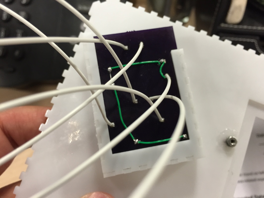
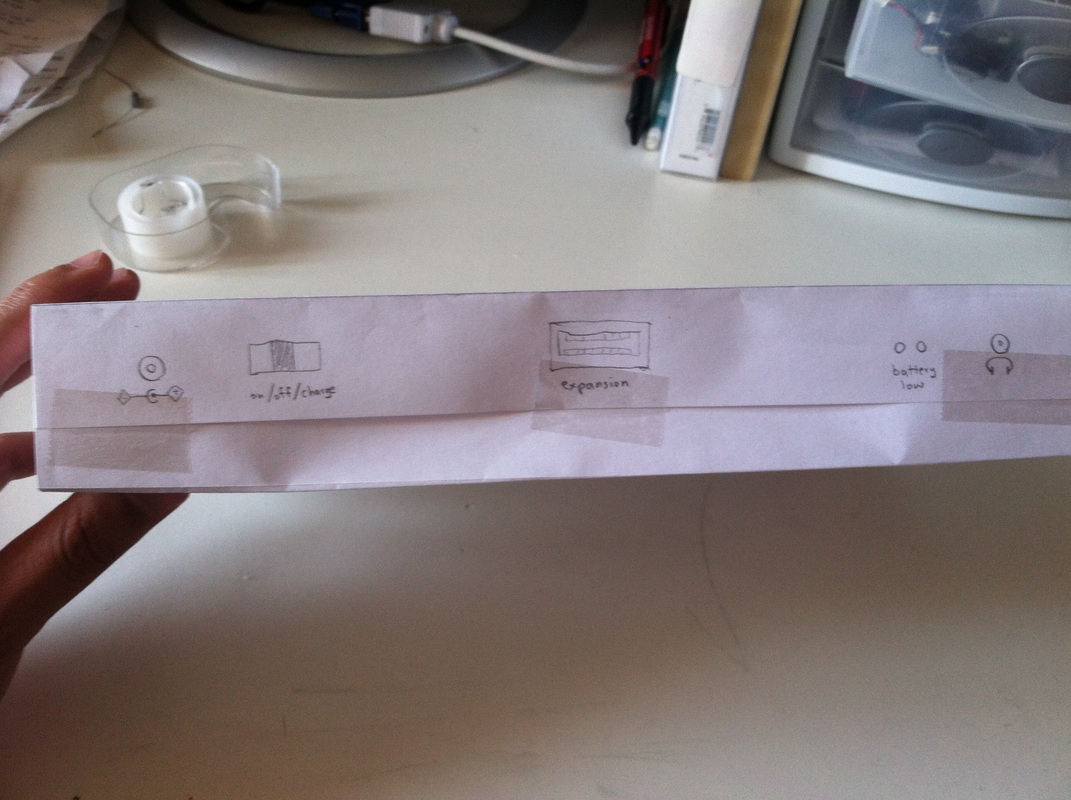
So you see the two batteries that charge via the charging port and the battery indicator lights at the left. Gonna aim to implement a multi LED indicator so I know relatively how much charge I have left. Looking into this design I found on electroschamtics which works well. I'll also do a mom-off button to activate it momentarily so I can see the state of charge while the unit is off, but i'll rig it so it's always on while the unit is. You also see two Fans wired to either the 3,3V or 7.2V. Not sure if I'll keep this since the fans I have currently are 5V puppies. We'll see. THe rumble pack gets its power from the 3.3V rail. Gotta look for a couple motors that work well at such a low voltage (or just bite the bullet and include a 5V regulator on here as well. I know the screen has one but I don't want to over use it). Gonna have a small selector switch for rumble vs save mode. Also thinking about a small switch for L vs Z function of the same button since I'm only including two buttons in the back. The headphone jack is pretty nifty in that it senses when something is plugged in and switches the audio output from the speakers to the headphones via the "headphone switch" signal input on the PSONE screen. The expansion pack will give me the ability to take AV out as well as all 4 players. I'm also using two of the pins to do a loopback so the console knows the expansion port is plugged in. This will cause the first player controller to shut off (no power going to it) as well as the screen to shut off (all together, no headphones working either).. Hoping this will all work. Finally, gonna try to add a PCB for all these connections and mount it somewhere at the bottom of the unit. Maybe it'll be able to carry the LED's and jacks and all that. we'll see. I want this unit to be reworkable in case I have to swap out a battery or something, One of my lipo's from last year already exploded and leaked in its bag so I'm kinda sad. On the bright side, I think I've thought of a really cool way to keep the face plate closed firmly while still being able to open it for repairs relatively easily. MAGNETS! But that's a month or so down the line... Next Steps:
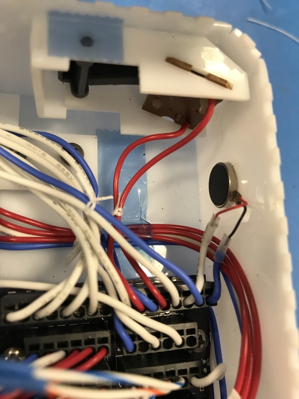
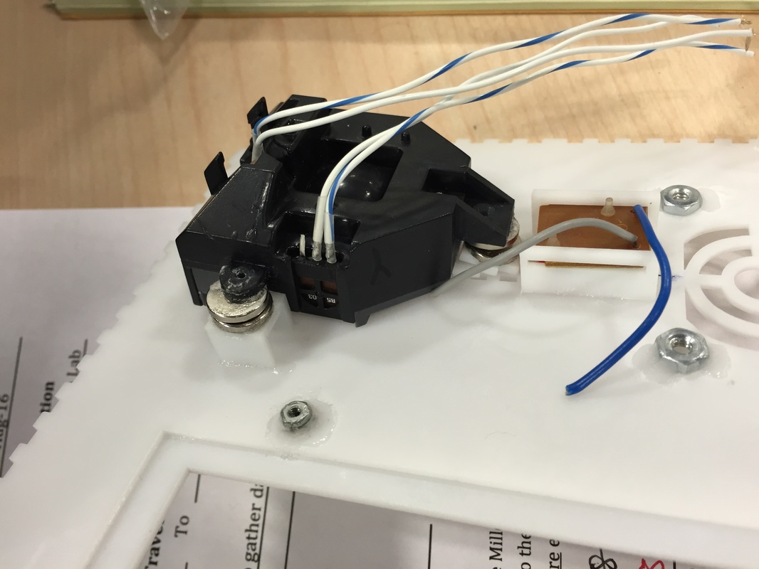
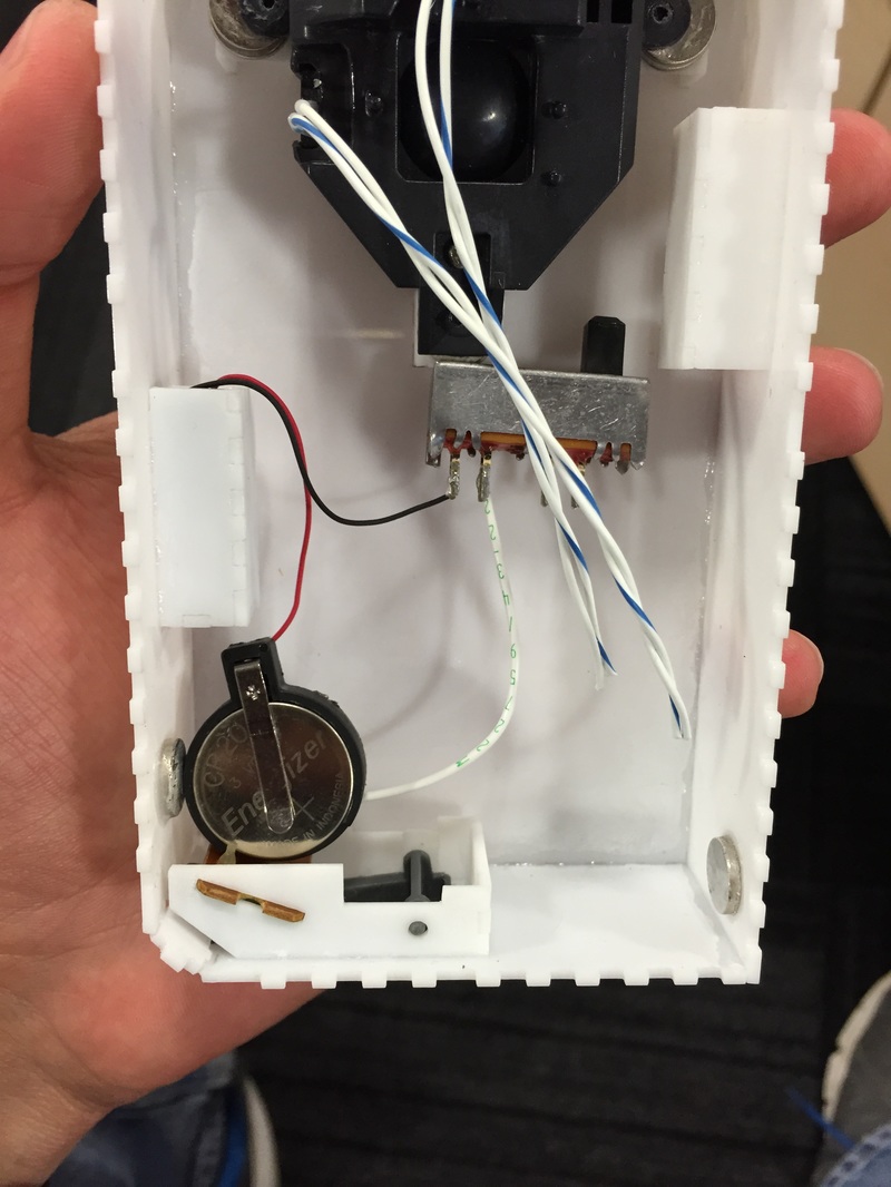
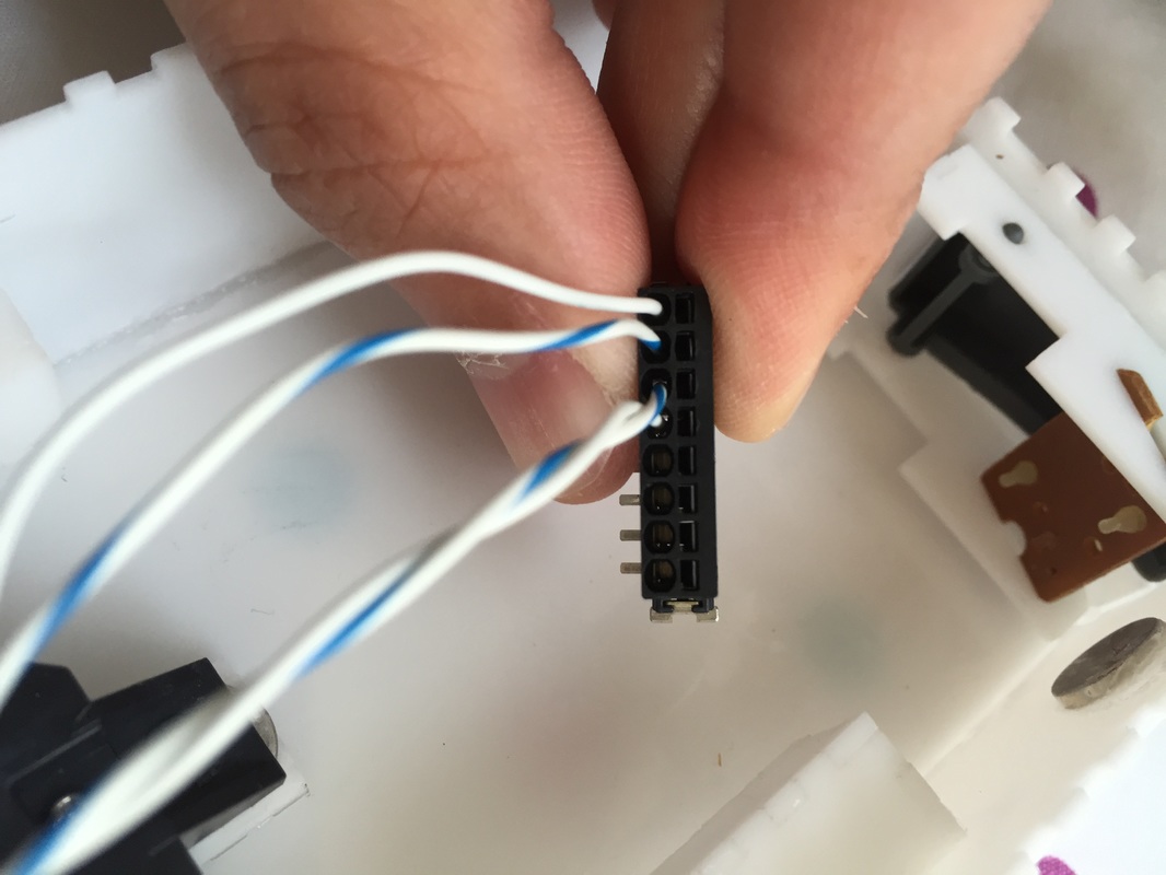
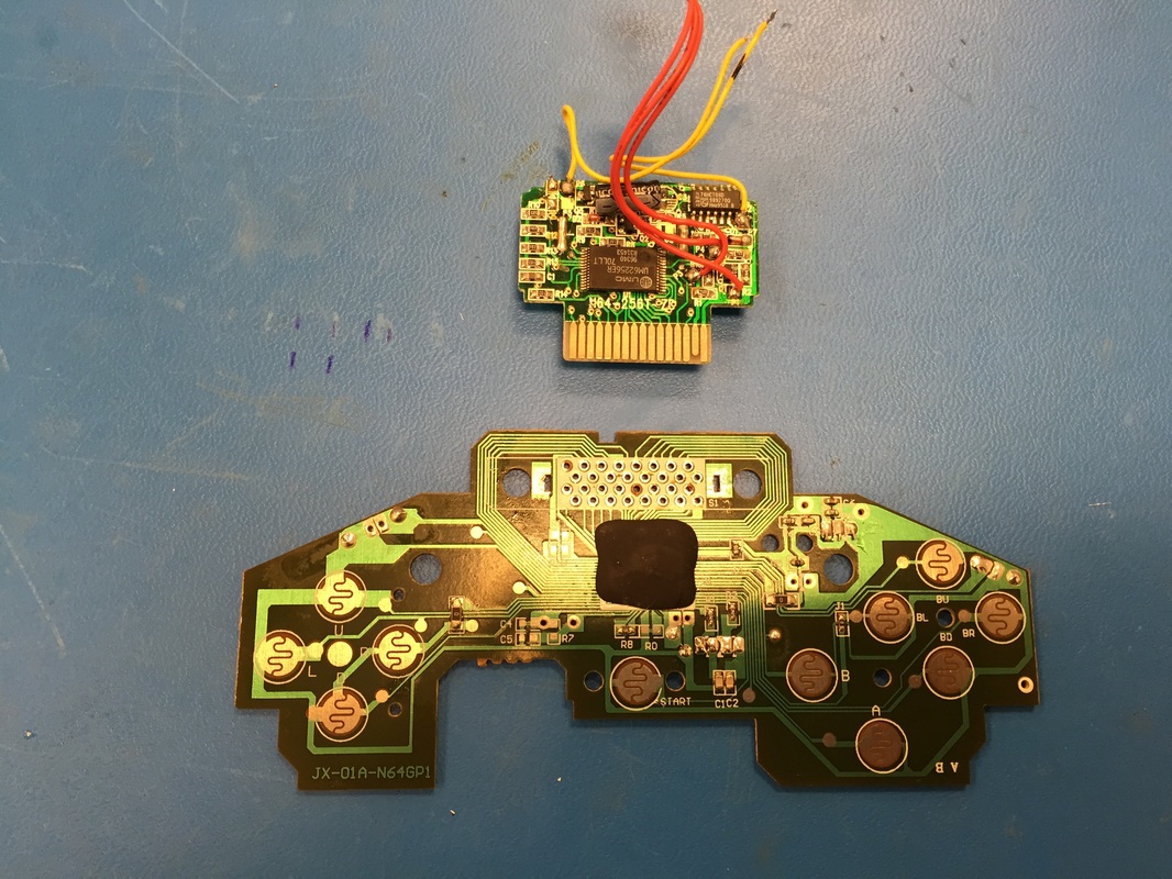
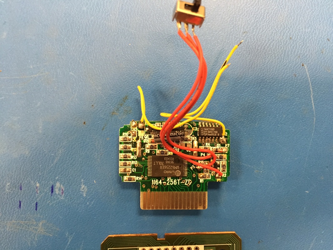
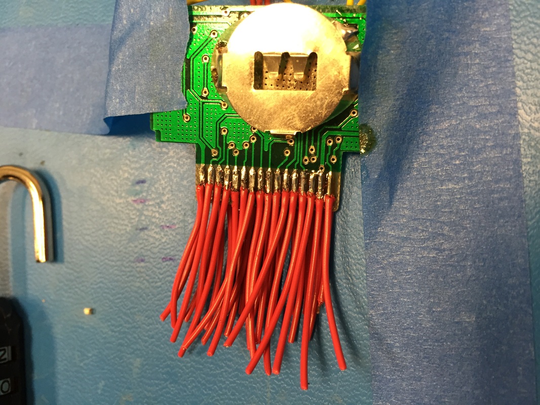
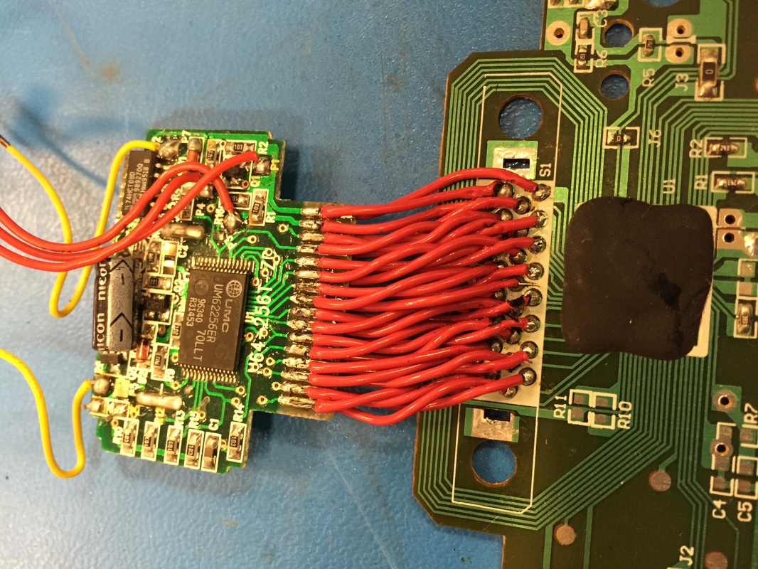
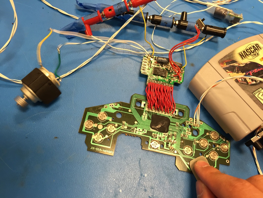
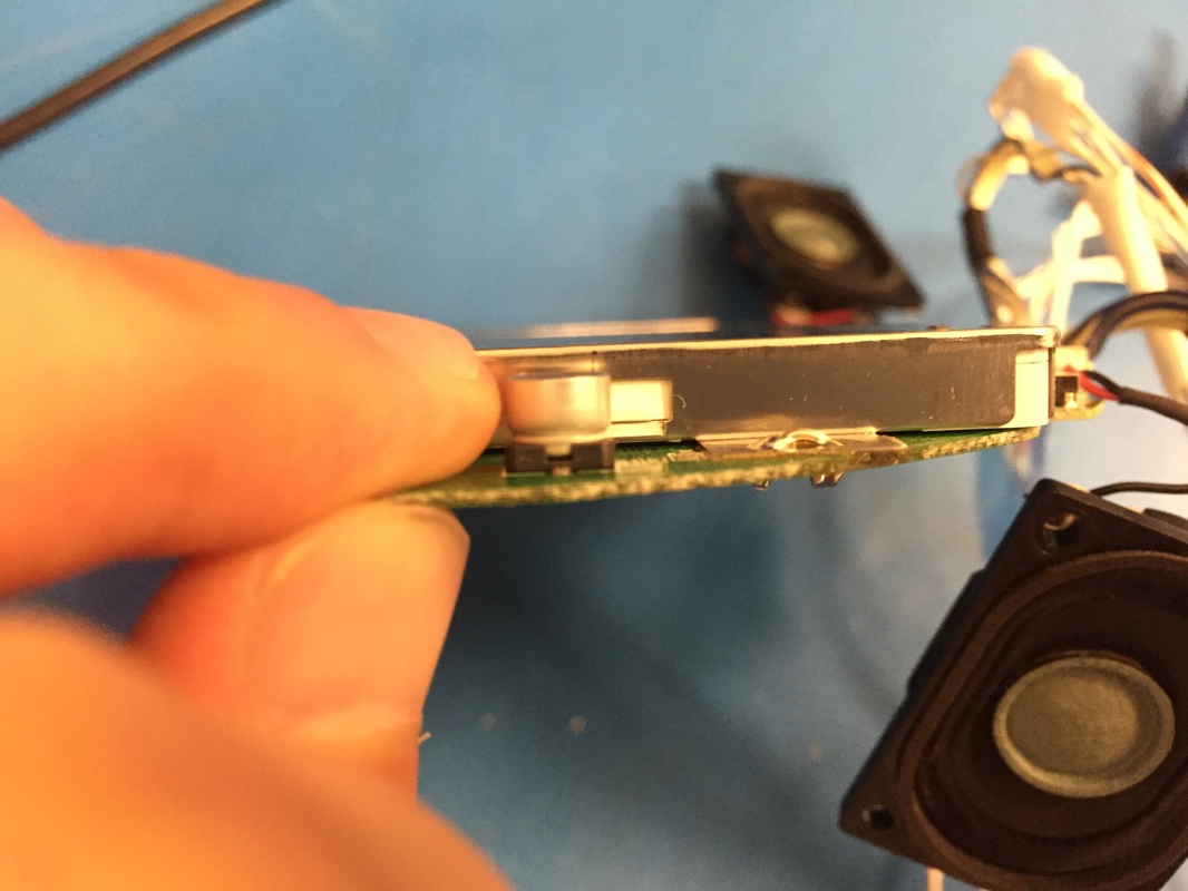
-Set resistor values and update block diagram -Do a power budget and see where I can save power (or swap components) -Start thinking about this PCB with push or screw terminals. Rumble Pak Had time to try out the motors today. I had 3 different vibration motors from different places. Ran them at 3.3V and they seemed fine even though they are probably rated only for 5V. I'll probably look into buying two identical ones from Digikey or something. The Rumblepak circuit board seems like the motor is connected to its batteries by a simple high side mosfet. The coin cell battery keeping the memory alive was dead so I'll have to replace that. But otherwise I'm gonna hook up two motors in parallel and hope that this circuit board can handle it. The motor that came with it drew about 100mA so maybe I'll find two and 50mA. The motor will connect to the 3.3V regulator where the two AA batteries would usual plug in. I moved ahead and soldered the rumblepak to the controller board. Lots of tiny wires with lots of places to mess up. Got pretty lucky and had no incorrect connections or shorts. One of the pads was completely torn from when I desoldered the connector so had to do some root canal and solder to the trace. Used the hole as strain relief. Wires are the same ones from the cartridge relocation job. In the last picture you can see the motor in action as it spins! Very excited, will try the memory stuff later once I get a coin cell replacement. For now I'll just leave the switch to go between rumble and memory short, but I gotta find a place for it on the case. Screen Mod LCD screens work with a backlight. Older LCD's use a florescent tube as a backlight but newer ones use LED's because they are more power efficient. Watch this video for a bit of reference as to how they work. The PSOne screen comes with a florescent tube bent into fitting on 3 sides of the screen. I used the two guides from my last post to help me take that tube out and replace it with LED's. The guides say to use 3 LED's but I used 4, one at each corner. Cut slits into the light box (most of the screen is really just the lightbox, not the LCD itself) and sneaked out the leads. The end result is a bit underwhelming, I thought it would be brighter, but It's not too bad from head on, any other angle and its not too good. Used 4 LED's with Vf=3.2V, strung them in parallel with a 15ohm resistor on the low end. This gives me about 30mA across each diode which should be plenty bright as you can see from the bits leaking out the corner slits. I noticed I could still control a bit of the brightness through the buttons on the board. Since the backlight is completely out the only explanation I could think of is that the screen color is being changed to a darker color rather than its brightness. This, coupled with the fact that its an old screen sorta makes me happy enough at how bright it is. I won't need brightness control for my console so just going to set it to the highest setting and leave it there.
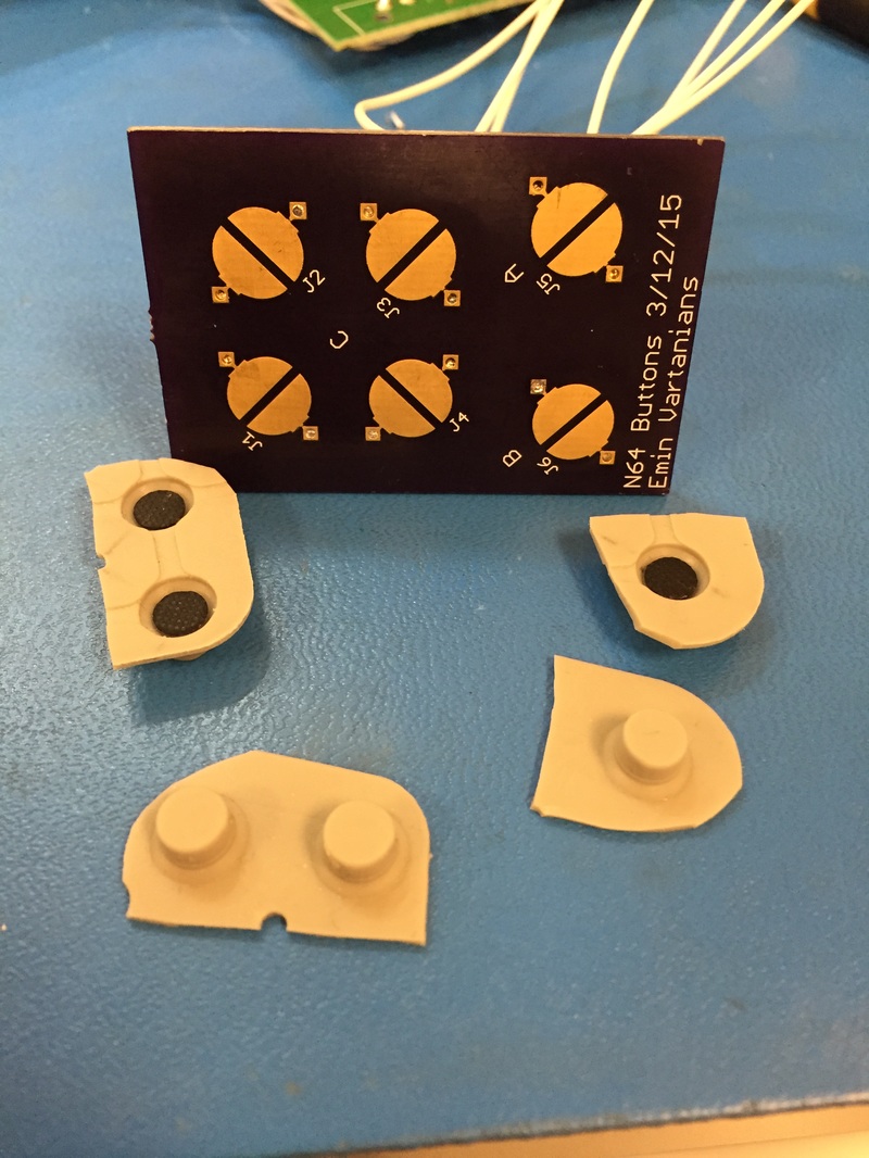
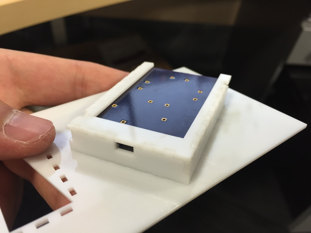
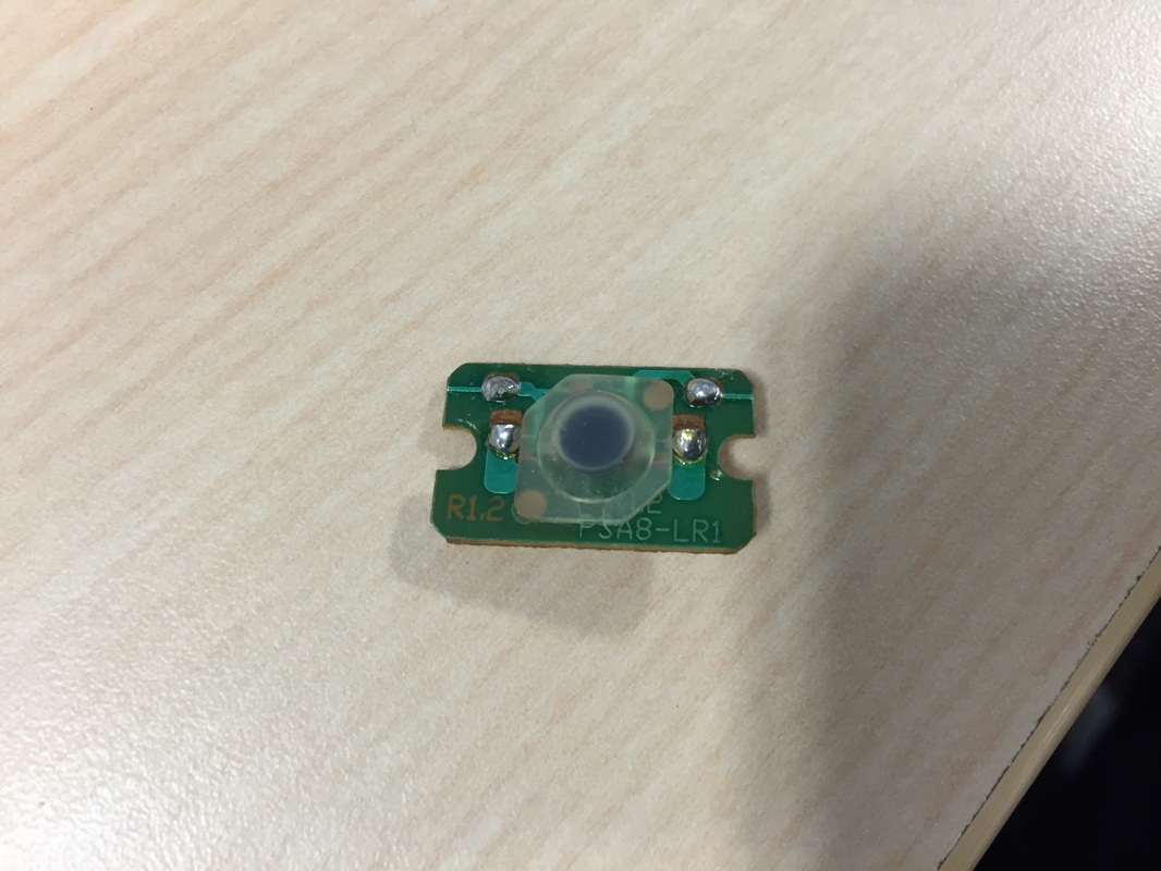
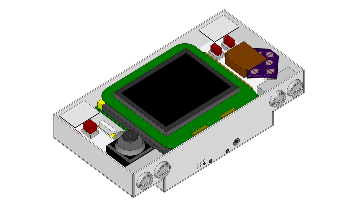
Take care to not short the leads of the LEDS together or to the case. I had to shear the metal case a bit as you can see to let the wires sneak through. Also desolder the transformer at the top since its not needed anymore. All together, the LEDs take 120mA. Add that to the 260mA that the screen takes with no backlight you get 380mA. This is way below the 600-900mA range that I observed before. I'm also thinking of adding a switch to turn on and off the fans for power considerations, or maybe even get a 5V linear regulator to have them operate at full potential (or have a 3 way switch to choose between 3.3V, 5V, or off!) Next Steps -Schematics/block diagram -Buy vibration motors -Buy Coin cell battery -Set up everything on the bench including the mosfets -Plug in and test AV and extra controller jacks -Finish up case (how do I hold the buttons in place?) -Get back the PCB I ordered and wire it up to controller LCD and Shopping LCD mod can make the screen draw way less power, one person claims it more than halved theirs... Worth a try! Read this and this for advice. Did a couple current measurements with regular screen vs unplugging the top Backlight connector: Total: Backlight=1.3-1.6A; No Backlight= 900mA Screen: Backlight=600-900mA; No Backlight= 260mA 3.3Vin: Backlight= 600mA; No Backlight= 600mA Board Battery: Backlight= 46mA; No Backlight= 50mA Board 3.3 Vout: Backlight= 1.3A; No Backlight= 1.3A So you can clearly see that the screen is taking a ton of power so I'm gonna try the LED backlight mod to bring down the total current consumption to less than 1.2A so that I can charge while playing (or at least have the charger keep up). Bought a few things from Digikey: 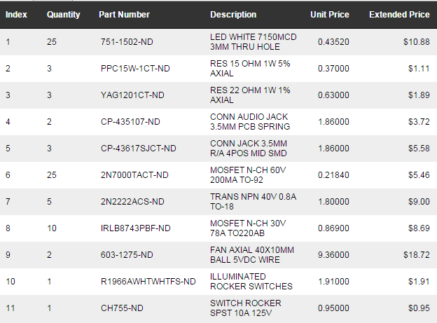 Case and Buttons Been working on the case concept designs with Sketchup. After a while of consideration I went with the one you see in the gallery below. Seen from the bottom, its got a "T" shape to it. This is to keep the grips as thin as possible so your hands don't get tired while playing (did not want a giant square box). Also thought about making it a vertical design but realized that I would run out of room pretty fast and it might be top heavy. My current design makes it so that I the grips are only about 35mm wide while giving me enough room to fit the batteries, fans, and rumble pak motors in the console. Gonna use the N64 controller A,B,C, and start buttons with the rubber pads. made my own PCB for the pads and got em at OSHpark. Two fans in the back will ensure I had adequate airflow, not sure if I'll have the blowing in opposite directions yet. They are 5V but I'll be running them off the 3.3V supply for now. All the peripherals will be at the bottom of the console since there's ample room inside for them to stick out. Gonna hand this to Tamar (Girlfriend) to Cad up correctly with wall thicknesses so that we can be ready for laser cutting as soon as all electrical testing is done.
Next Steps:
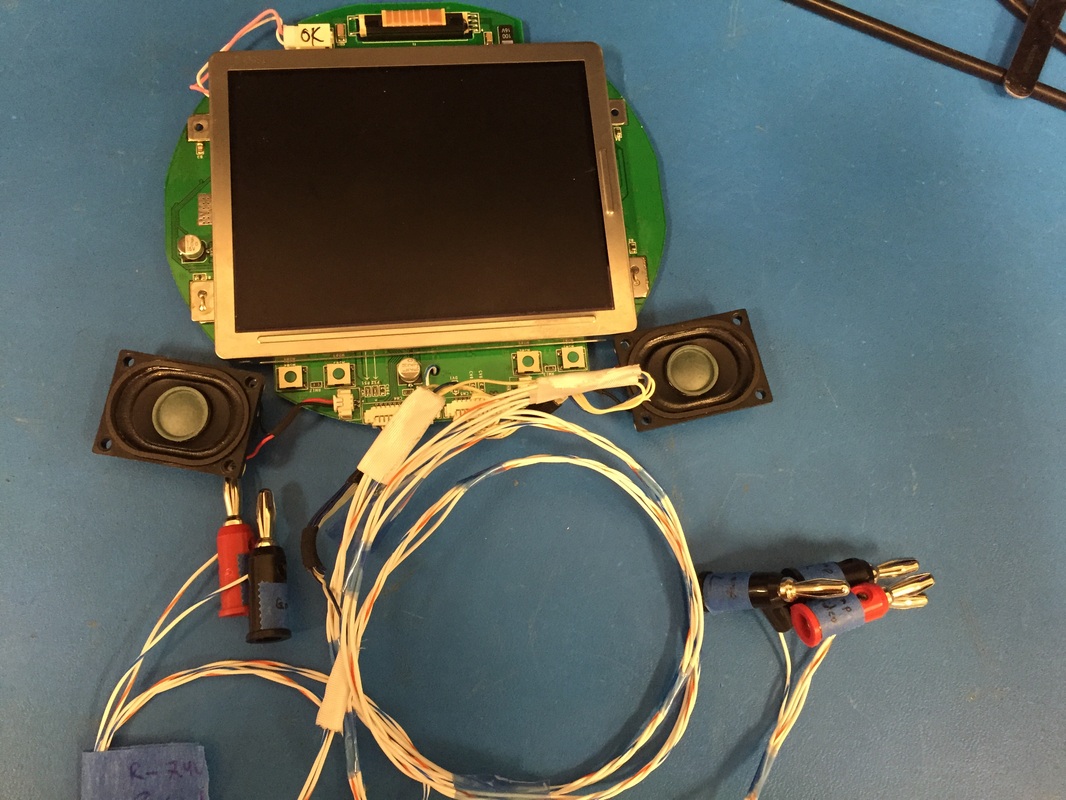
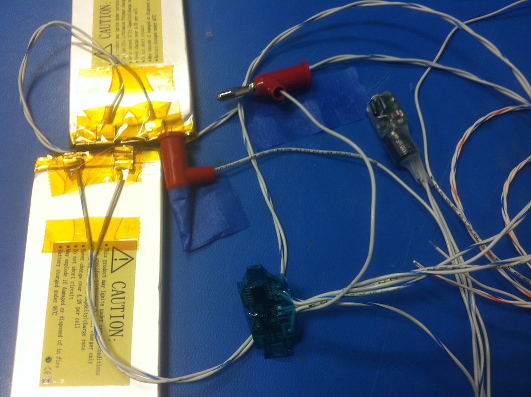
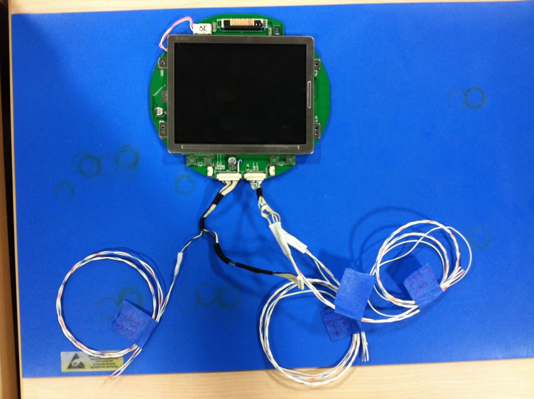
-Make schematic of everything -Solder rumblepak to controller and test -Verify I can run the motors together -Carry out LCD backlight Mod Had put this project on hold for a while. I think the mechanical aspects of the console really intimidated me. So with the help of my girlfriend (architect!) i'm moving forward with the project and enlisting her help in designing the case. We will laser cut it out of 60 mil white acrylic and assemble with glue and notching. Still working on the in's and outs... While she focuses on the case design I dusted off the electrical components. My soldering job wasn't very good and many connections had broken. So cleaned up a bit, put heat shrinks on the cartridge connections and added banana plugs to everything for ease of prototyping on the bench. I'll be soldering connections when the systems in the case since banana plugs won't fit in the there. I also made sure to include strain reliefs wherever I could. Lastly I secured the screen to its driver board through some bus wire. The aluminum shielding wouldn't directly solder to the PCB pads for some reason. Powered up the system and It all works great!
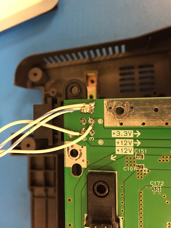
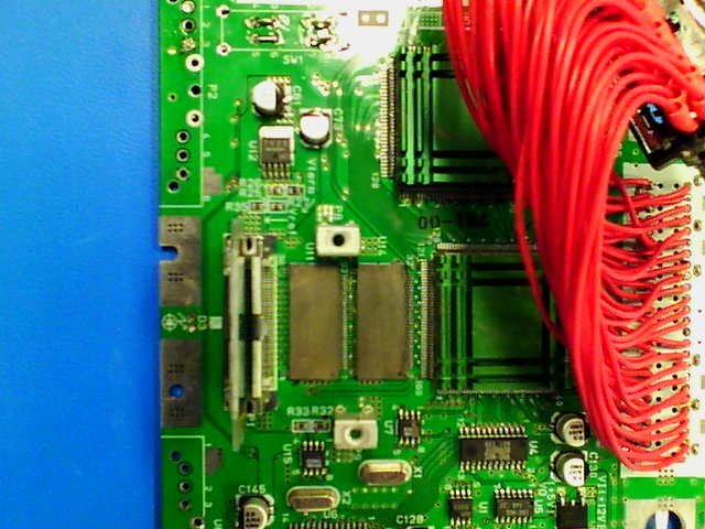
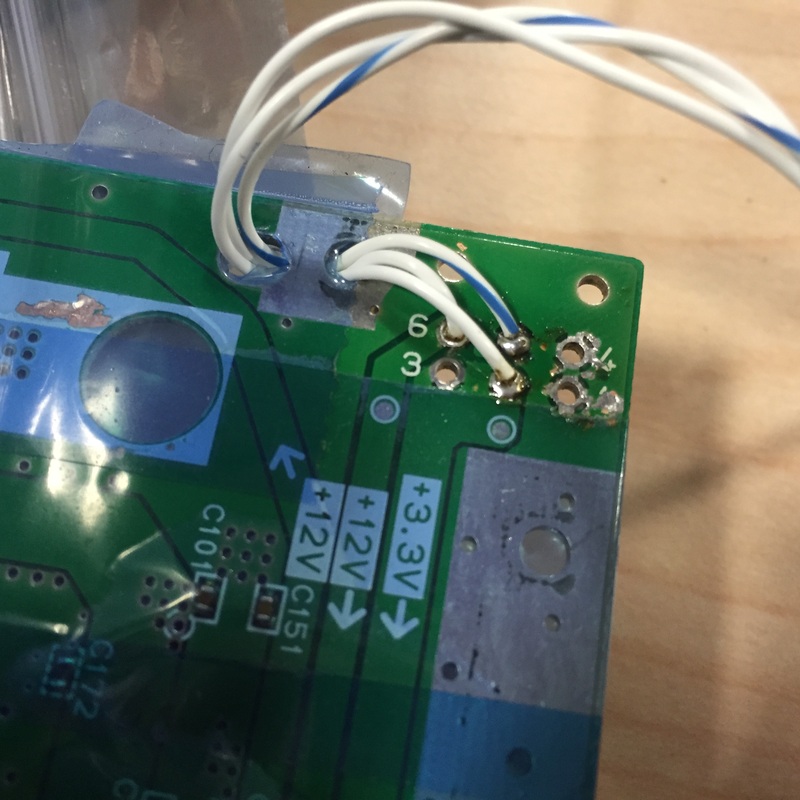
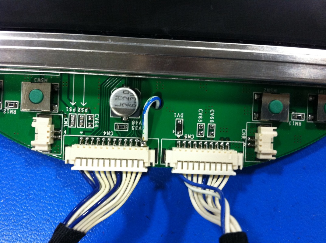
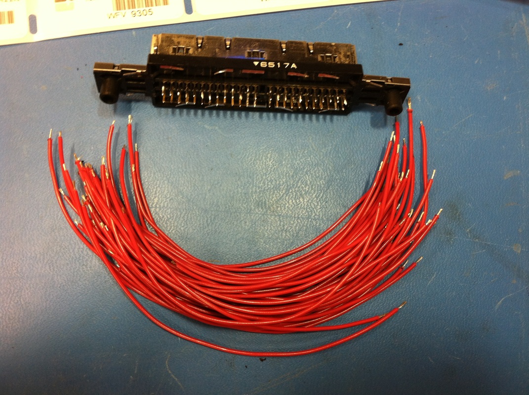
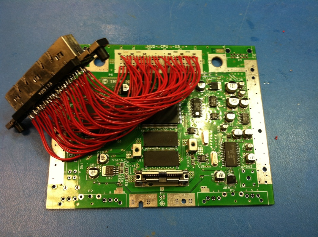
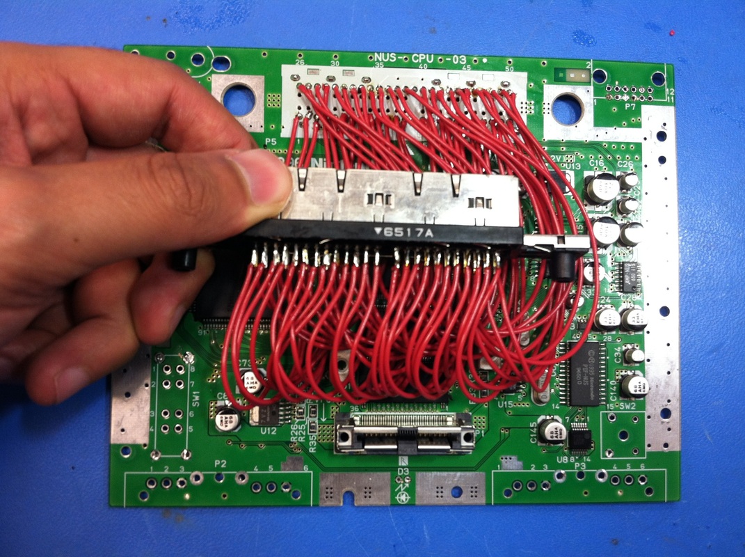
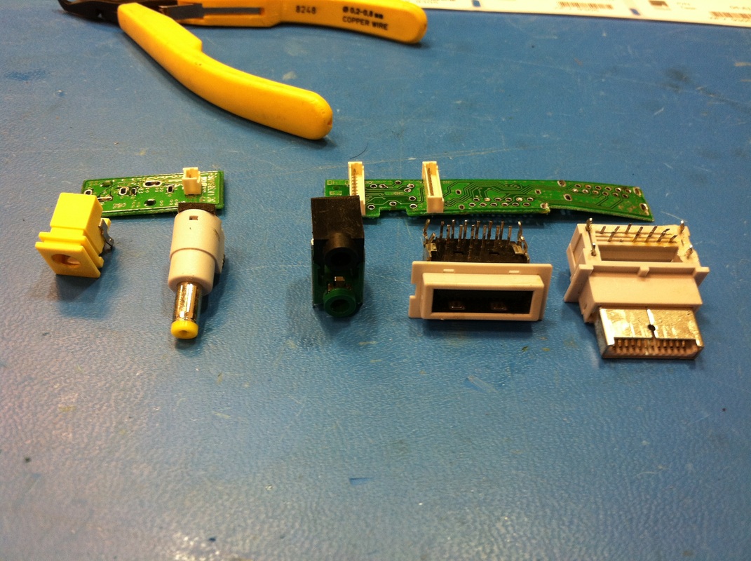
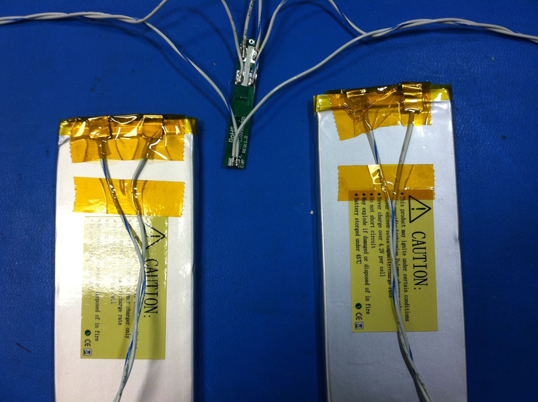
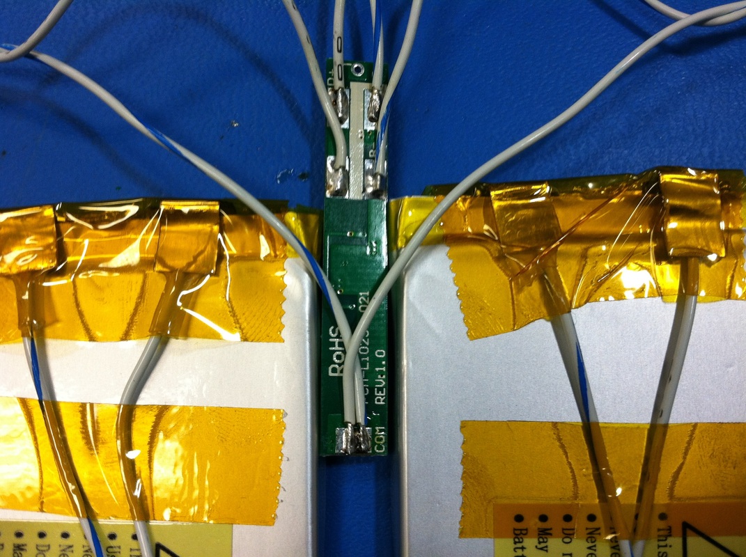
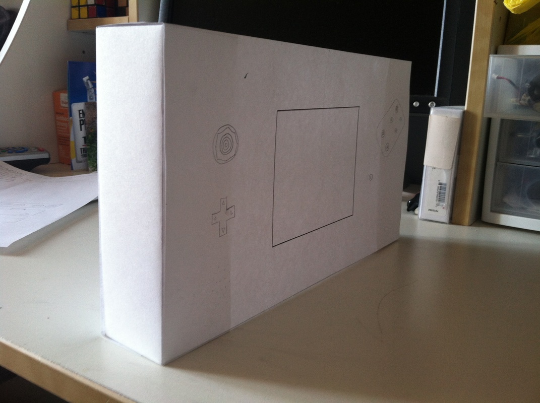
One thing I found was that the 5V sense line on the screen doesn't seem to be doing anything. All the guides online say that you should tie that line to the 5V regulator on the back of the board to turn on the module but when I disconnected the module still worked. Even grounded it and it stayed on. Gonna leave it connected but will have to disable the screen by pulling power to it. Need a power transistor since the screen pulls 0.5-1A so will look for a thru hole version of that for testing. Also gonna need a tiny fan in there...we'll see if there is room inside. Lastly, decided to build my own button pad pcb to detect the A, B, and C buttons using the original control's components. This thread has some good insight into layout out your own button pad pcb. Insights like "you're PCB needs to be ENIG treated so the pads don't tarnish". Lucky for me OSHPark already ENIG treats all its boards for free. Next steps: -Exact dimensions for anything protruding from the case so that laser cutter can do its job correctly -Polish the schematics/block diagram with part numbers -Order parts -Design and order button pcb -Test everything on the bench Exciting times! Busted out the Dremel today to do some cutting. The case cut (melted) semi well, I cut the lid to size and got a great cartridge slot in the back. Broke a few tips here and there but they're cheap. When I started to cut the extra plastic I had bought to make the cartridge backplate my Dremel started crapping out. Made way too much noise and blades started breaking more often. I'm gonna look for another route here. Either scrap the whole case and get one 3D printed from some online shop (like emachineshop) or find and buy thinner plastic for the backplate. I figure if I spend a bit more money then I can get exactly what I want without any of the cutting hassle. I'll have to shop around a bit. I also applied some thermal compound (google, radioshack, anywhere) to the big chips on the motherboard and put the heatsinks on. Found them on eBay, tried to get as thin as possible. Searched "BGA heatsink" I think. Tacked those onto the chip with a dab of superglue on each corner so they stay put and I was done . BatteriesGot my replacement battery protection board in the mail. It seemed to not work at first but after a while it showed 7.4V on the output. I'm guessing it had to fill up some capacitors or something. Either way I got it wired up the way the diagram in the package said and put shrink tubing around the board for protection. Then I wired it to the main board along with the 3.3V regulator, which is a Texas Instruments module (PTH08080WAH) that takes in the 7.4V from batteries and turns it to a settable voltage (set to 3.3V by a 2K resistor). I also wired up a low voltage detector found here. Where the two wires stick out on the back view is where the red and green LED's attach once I thread them through the case. ScreenWired the screen according to the general schematic I had posted in a previous post. Took advantage of the cables that came with the PSone screen. Also wired the output of the 5V regulator to pin 12 of one of the headers which turns the screen on. I'm using bacman's pinnout and keeping the composite video and audio, headphones, and power. The headphone switch turns out is internally pulled high. If you want the speakers to work you'll have to ground that wire. I'm gonna eventually put it on a switch or something. Putting it TogetherWired everything up and it works! got music out of the speakers too. Really excited about the progress. Next up will probably be case modding. Got some supplies that I'd ordered in. Big thing was 100 feet of 26 AWG stranded wire. Flexible and strong. Cut 48 of them into small pieces, stripped and tinned the ends, then got to working on the cartridge slot. A whole lot of tedious work. Won't know if it works until next week when I can power the whole thing with the PSone Screen. Also desoldered the connectors from the PSone screen base. They'll come in handy later for power, expansion, and A/V connections. Lastly I got these Single cell Lipo batteries in series and hooked them up to a protection circuit. The batteries will work with this specific charger designed for double cell battery packs. Note to self: don't short batteries on the protection circuit. I fried the board so I'll be getting a new one. Just glad the batteries are still fine. I soldered onto the battery tabs, shrink tubed them, and taped em down for strain relief. Not taking any chances. Will be shrink tubing the protection circuitry board as well when the new one shows up from Batteryspace.com Found a great site for reference. Has ideas for cases, batteries, and the screen. Also this general schematic of Bacman's portable. Good reference for a start. I started thinking about the enclosure and realized that since I'm a noob at portable console moding I shouldn't be pushing the boundries on space for the electronics. So I'm gonna look for a nice rectangular project box to build this thing out of. My initial estimates are: length: 10-12 inches Width: 5.5-6.5 inches Depth: 1.25-2 inches Length is driven by the console itself which is at 6.5 inches, so I figure with some room on the side for controls, 10 to 11 is a good number. Width is driven by the PSone screen board, It's at 5.5 pretty snug and if I want some plugs underneath I should make it a bit bigger. The Depth is driven by the boards stack up as well as comfort in holding the portable. I made a little mockup of the portable using length=11 inches, Width=6 inches, and depth= 1.75 inches. After holding it in my hands I got a lot better feel for the dimensions. The Width is perfect at 6 inches. The Length can be contracted a little, maybe 9 inches or even 8.5. The Depth has to be increased I think. The boards are gonna be too squeezed in there for my comfort. Gonna shoot for 2 inches for that.
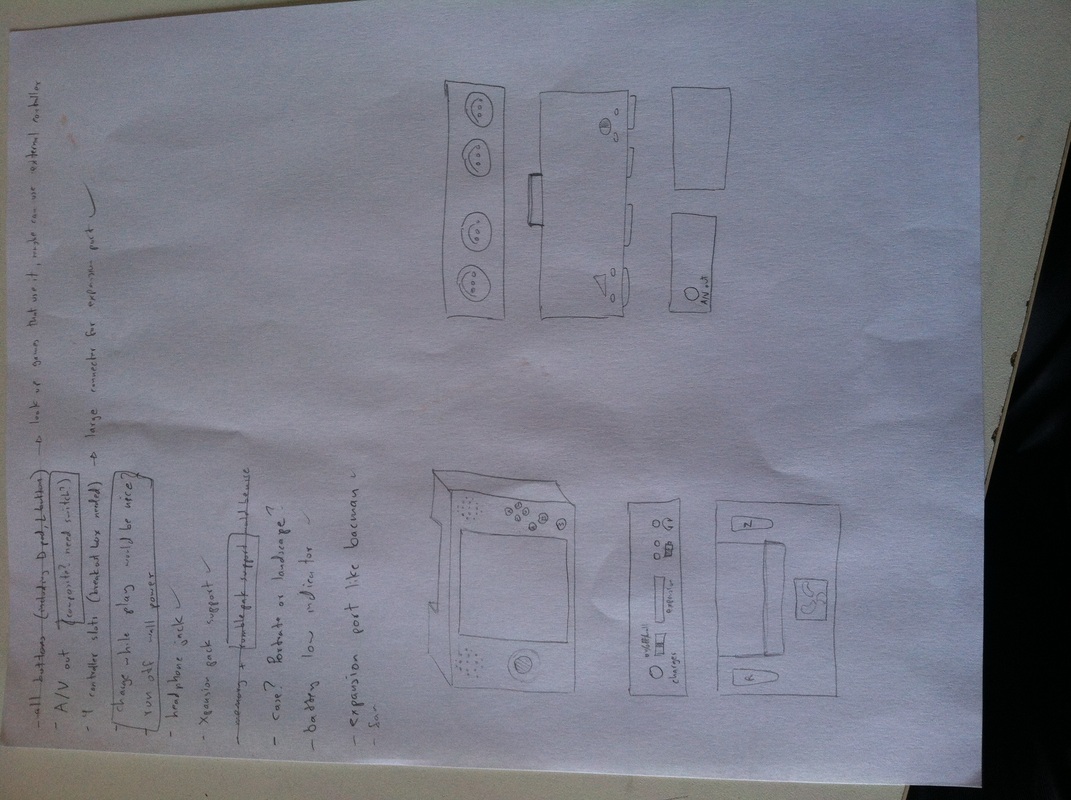
You'll see in the pictures that I have a few switches on the bottom:
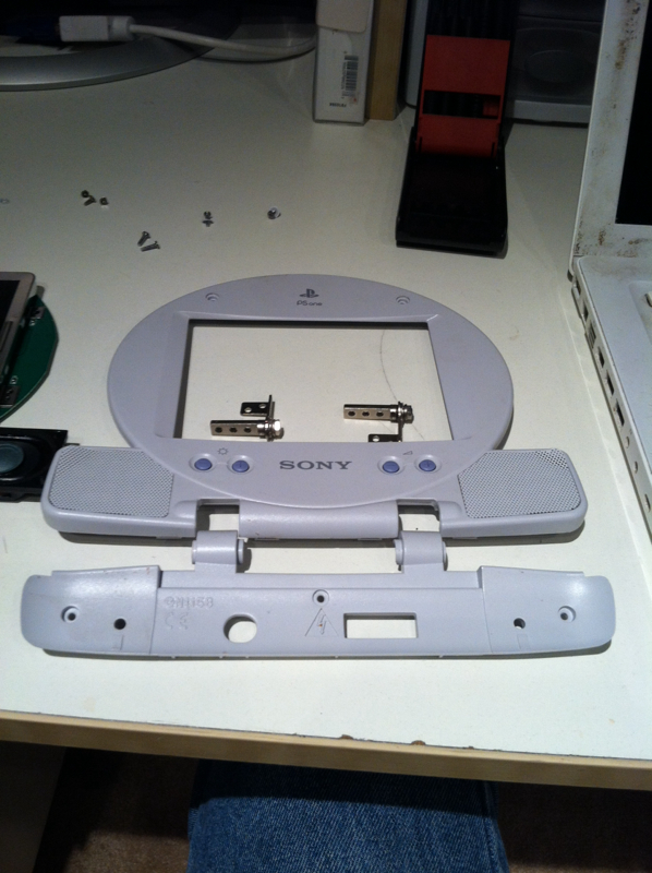
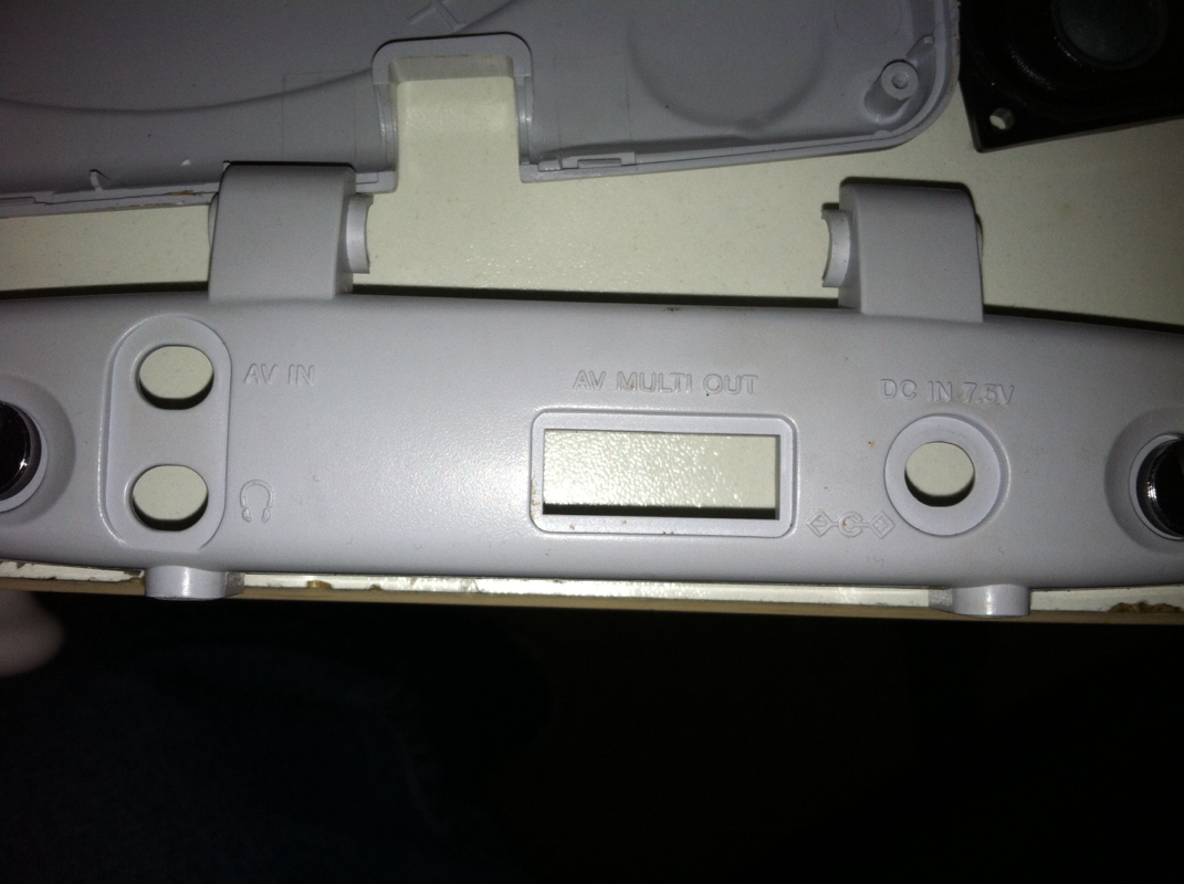
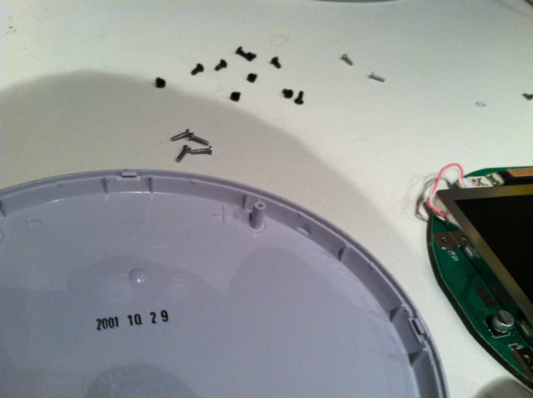
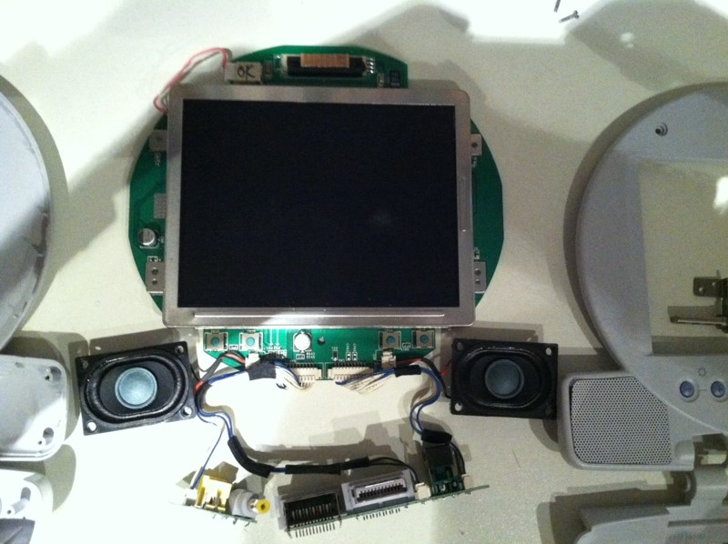
I've also done away with the L button, and might take off the D pad as well. I figure so few games use it that If I really need it, I'll play with an external controller. Got the PSone screen Off ebay for $65. Great price i think. Havn't plugged it in yet as I forgot i need a 7.4V supply. I'll have to build it on a breadboard later and prove the thing works. I'm still working on features i want and the kind of case to shoot for. Got my Gambit screw driver in today and started opening the case! Got everything i could off the board. I'm right before the step where I break out the dremmel and wire clippers. Gonna research and order an enclosure before going any further. Gotta still wait for my rumble/memory pack to get in before I tear stuff up. Gonna also need a schematic/block diagram and a list of things I have yet to buy. But so far... It still works! 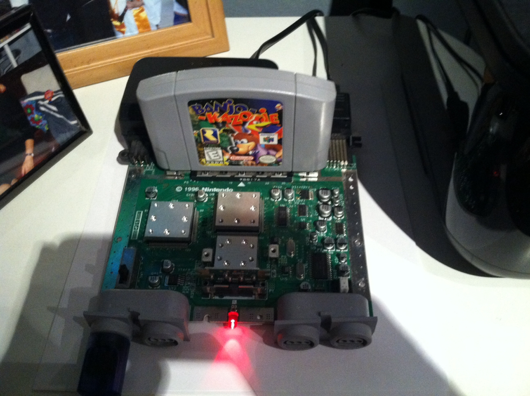
|
|||||||||||||||||||||||||||||||||||||||||