Box
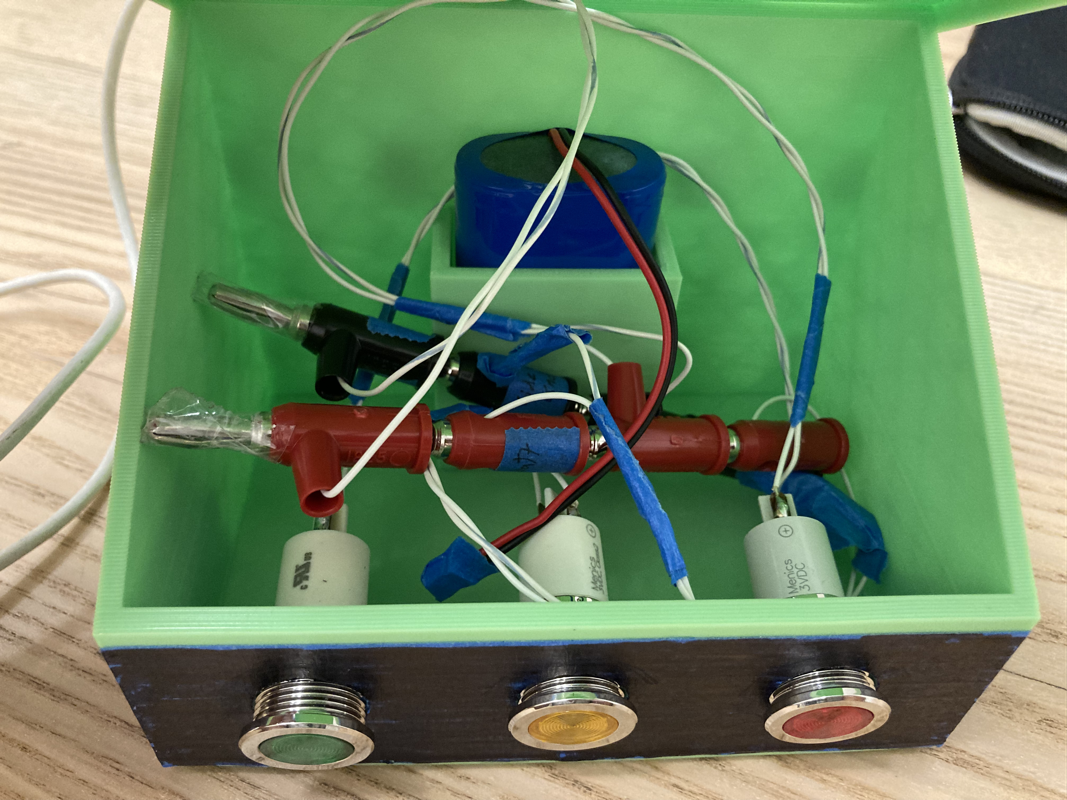
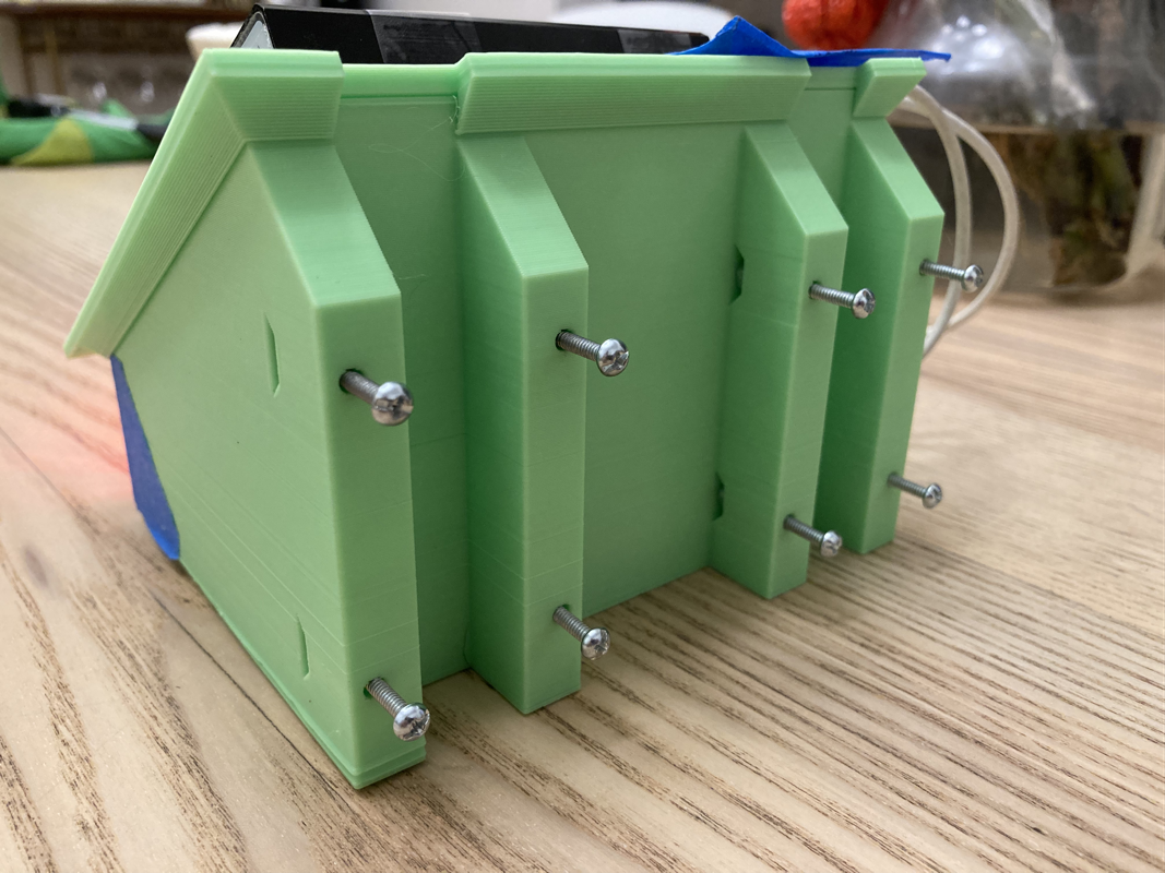
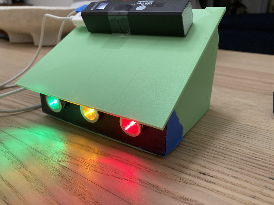
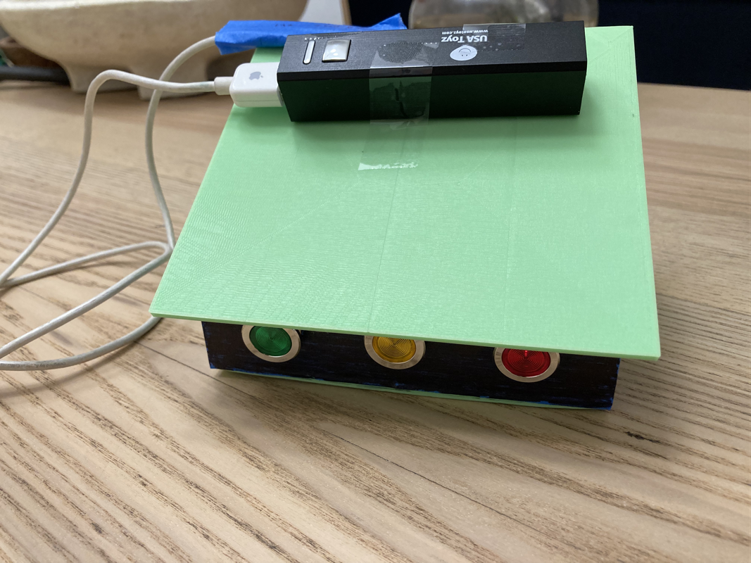
Used the online version of sketchup to CAD the box. It'll be 2 parts and 3D printed on our Ender3. There's the top "hat" that the solar panel mounts to (and I think the little charger board will be there too) then there is the base that houses everything else. I did a test piece with this neon green filament we had to make sure what I'm thinking makes sense. There is a clamp thingy on the back side too to hold onto the railing on the gate. I wasn't sure about this but I think I'm gonna leave the top and base unfastened. The fit is tight enough to not fly off in the wind and I got this bevel around past the edge so it's not an air tight seal but water can't get in. Tried out the lights (which are canted down now at 10 degrees! so I can see them from inside the car). My goal has been to be able to see the lights during the day. It's obviously not as bright during the day but I think I can tell the difference between lit and unlit lights. taped on a USB power pack on top just to be able to test it outside.
Used the online version of sketchup to CAD the box. It'll be 2 parts and 3D printed on our Ender3. There's the top "hat" that the solar panel mounts to (and I think the little charger board will be there too) then there is the base that houses everything else. I did a test piece with this neon green filament we had to make sure what I'm thinking makes sense. There is a clamp thingy on the back side too to hold onto the railing on the gate. I wasn't sure about this but I think I'm gonna leave the top and base unfastened. The fit is tight enough to not fly off in the wind and I got this bevel around past the edge so it's not an air tight seal but water can't get in. Tried out the lights (which are canted down now at 10 degrees! so I can see them from inside the car). My goal has been to be able to see the lights during the day. It's obviously not as bright during the day but I think I can tell the difference between lit and unlit lights. taped on a USB power pack on top just to be able to test it outside.
Electronics
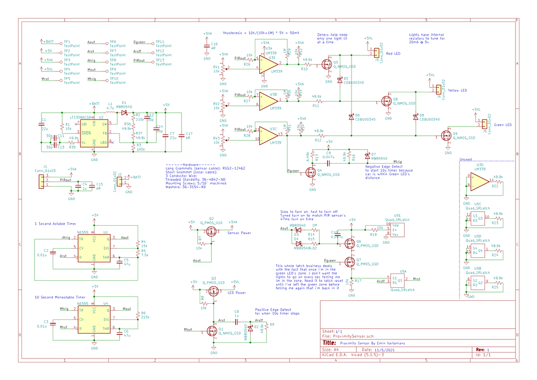
I transferred everything from LTspice to KiCAD. Had to make a couple new symbols but in general I tried to work with what's already in the libraries. I got lucky with many of the parts on here too, tried to use as much as I could from the parts I already had in my bin (so in some places I got multiple caps or resistors in series because I didn't have the right value in my bin but could build it up). I also added test points and tons of notes to the schematic so I know what the heck is going on in a few months when something isn't working.
I still have to work on a couple things though. The hysteresis on the comparators isn't completely clear to me, plus I had a clever scheme of having big resistors in series with the outputs so the Schottkies could clamp the "further" LEDs off but I gotta make sure it still works.
| proximitysensor_sch.pdf |
