Pretty Board
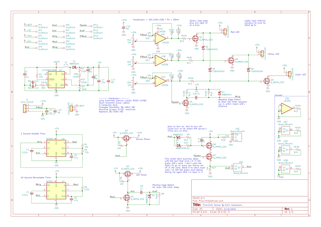
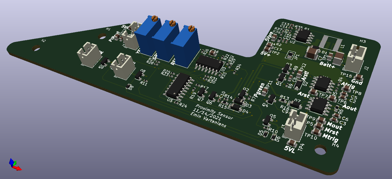
After the back and forth of the Nixie Watch I had forgotten how quick a design cycle can be. I finished the schematic, laid out the board, and had a real BOM in a week or so. So I thought I was gonna have a board that matched the internal shape of the birdhouse but it seemed excessive. Managed to fit everything on a 2 sided board, components on one side only, and use up less area than allotted (yay I can still be clever). The bottom layer is a split plane ground shared with 5vLED and 5vSensor. I also was forced to route most of the power through traces as opposed to pours but the max current we're talking about across the board is 30mA, so let's say 50mA worst case with inefficiencies at the input. A 20 mil trace ought to handle that just fine. My normal trace n space I set as 10/10 with a via size of 20/12 mil. So the whole board is about 11 square inches enveloped which made BatchPCB's service cost $55! so I went with JLCPcb which was like $6...sprung in an extra $2 for black solder mask. With shipping it came out to $11, really crazy cheap. Oh I also made weird choices on the component selection and passives in series/parallel based on what I already had in my pile. You'll see weird values or choice in the schematic or pads doubled up for no reason, my growing pile of SMT's was the reason, extra challenge I suppose. I marked what I needed to buy vs what I already had in the BOM as you can see. The BOM also contains the hardware like grommets and standoffs so I can track it all in one place.
After the back and forth of the Nixie Watch I had forgotten how quick a design cycle can be. I finished the schematic, laid out the board, and had a real BOM in a week or so. So I thought I was gonna have a board that matched the internal shape of the birdhouse but it seemed excessive. Managed to fit everything on a 2 sided board, components on one side only, and use up less area than allotted (yay I can still be clever). The bottom layer is a split plane ground shared with 5vLED and 5vSensor. I also was forced to route most of the power through traces as opposed to pours but the max current we're talking about across the board is 30mA, so let's say 50mA worst case with inefficiencies at the input. A 20 mil trace ought to handle that just fine. My normal trace n space I set as 10/10 with a via size of 20/12 mil. So the whole board is about 11 square inches enveloped which made BatchPCB's service cost $55! so I went with JLCPcb which was like $6...sprung in an extra $2 for black solder mask. With shipping it came out to $11, really crazy cheap. Oh I also made weird choices on the component selection and passives in series/parallel based on what I already had in my pile. You'll see weird values or choice in the schematic or pads doubled up for no reason, my growing pile of SMT's was the reason, extra challenge I suppose. I marked what I needed to buy vs what I already had in the BOM as you can see. The BOM also contains the hardware like grommets and standoffs so I can track it all in one place.
| Proximity_sensor_output_pdfs.zip |
Panel Mount LEDs
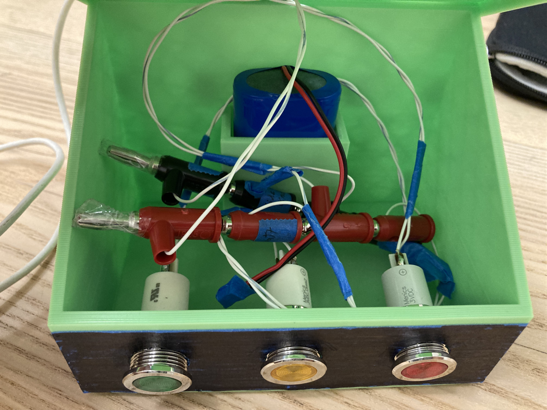
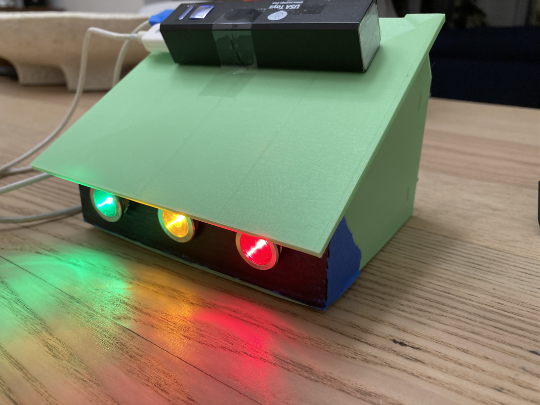
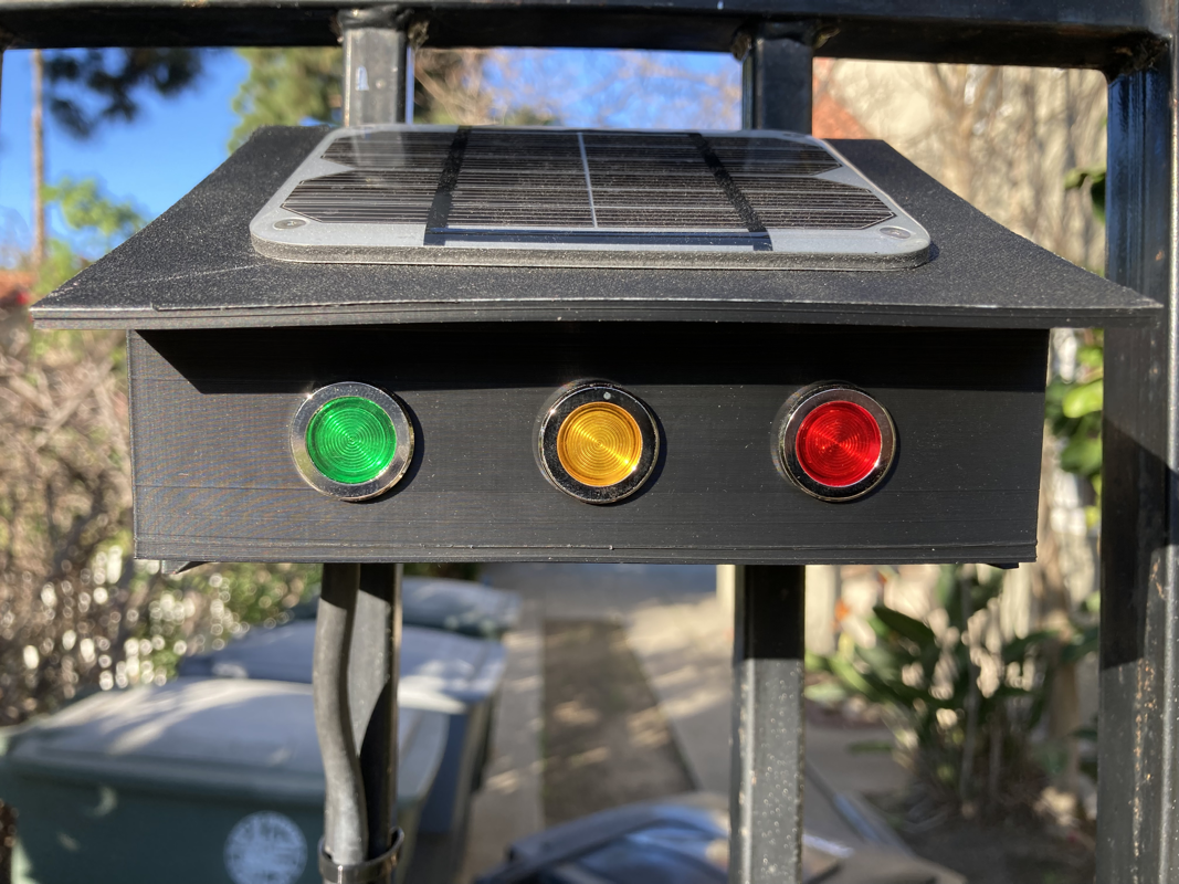
I had bought a Red-Yellow-Green trio of panel mount LEDs from Digikey, manufactured by Menics part number H16F-03G. They are rated for 3V input but I opened them up to find a beefy SMT resistor inside because the LEDs themselves are like 2v parts (duh). So I replaced the resistor with the correct value to get 20mA off of 5v (closer to 15mA for the Green one since it was brighter for some reason...). So now I can just plug these puppies straight into the board's 5v supply with no external resistor!
I had bought a Red-Yellow-Green trio of panel mount LEDs from Digikey, manufactured by Menics part number H16F-03G. They are rated for 3V input but I opened them up to find a beefy SMT resistor inside because the LEDs themselves are like 2v parts (duh). So I replaced the resistor with the correct value to get 20mA off of 5v (closer to 15mA for the Green one since it was brighter for some reason...). So now I can just plug these puppies straight into the board's 5v supply with no external resistor!
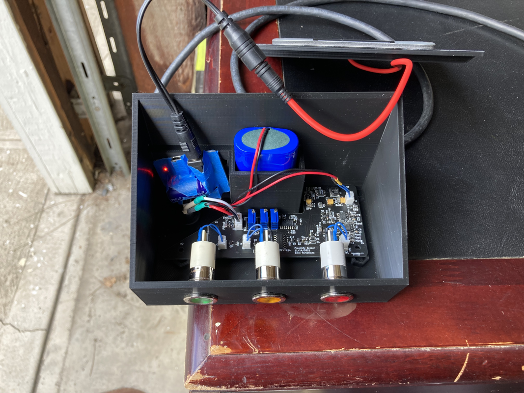
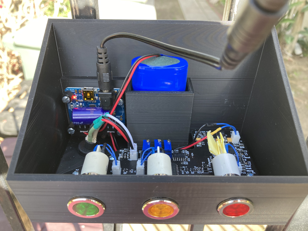
Boxes are Done
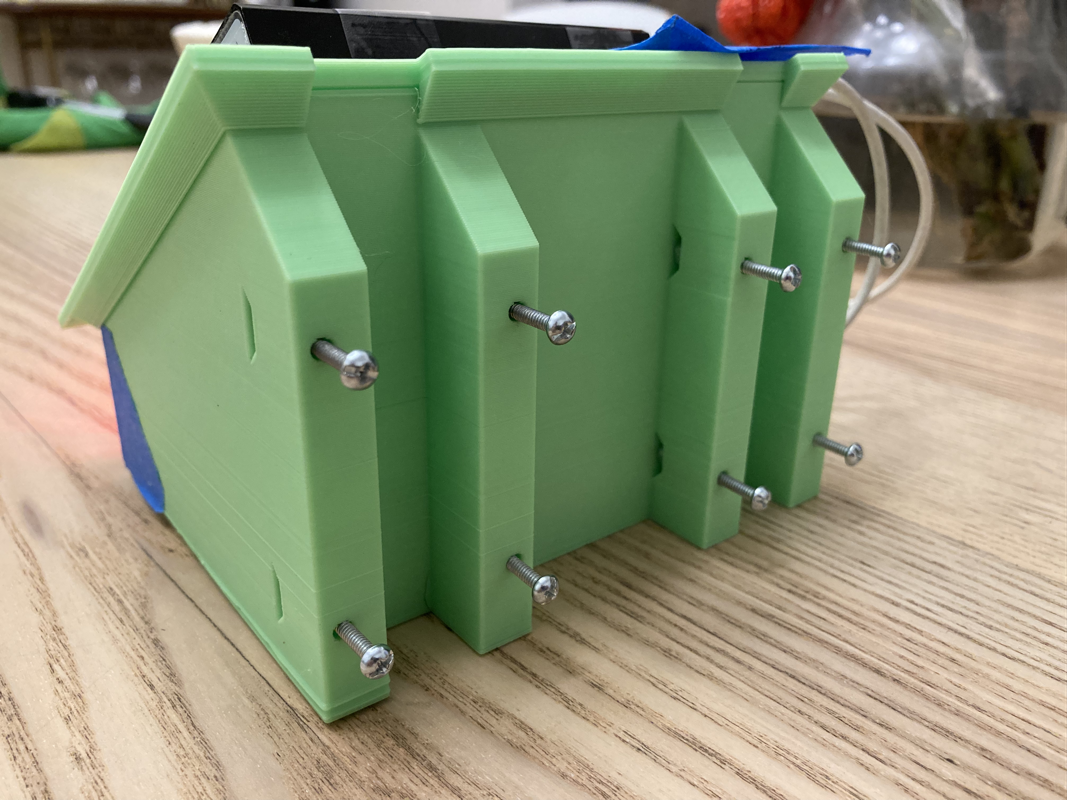
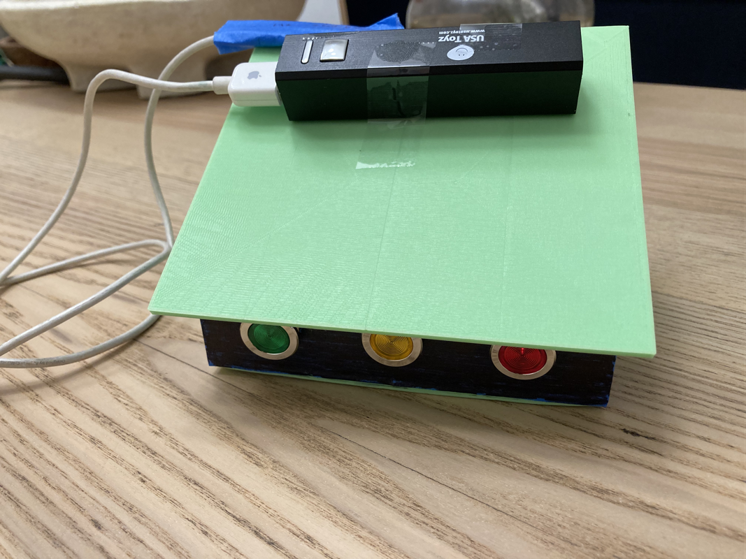
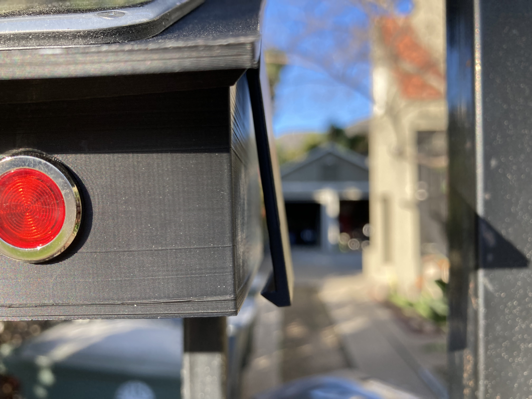
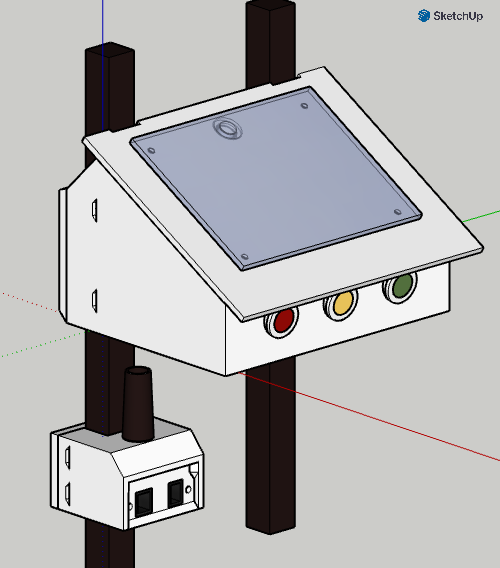
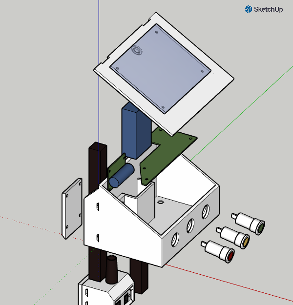
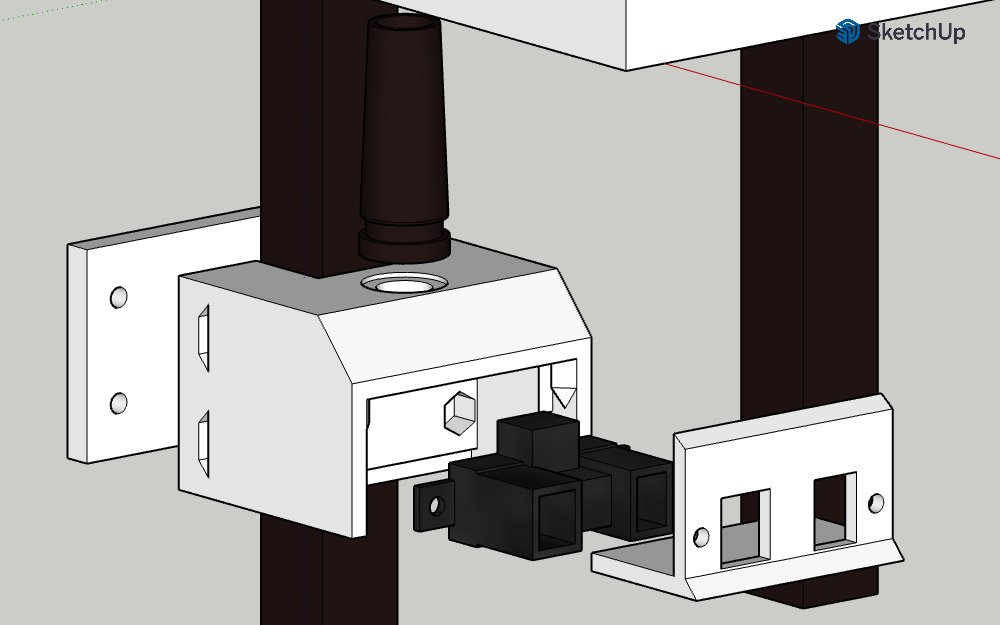
I should off the birdhouse design last post which houses the battery, charger, LEDs, and the PCB. Had to do minor changes to that to fit my railing plus plus added little spots for nylon threaded 4-40 standoffs to be glued into place so I can hold the boards down. I widened the holes for the lights (gotta make a test piece for this to make sure). Also modeled the PCBs in and got the hole in place for the sensor and solar wires. Hopefully the grommets are good enough to keep weather out. I also have a small sensor box which houses the actual sensor to be mounted closer to the bumper connected with the wire (got that outdoor rated wire from my electrician dad!). I initially had the sensor box modeled too tight so for this first test print I filed the edges down to make it sit in it's slot. It was also too tight to install with the sensor so I redesigned it to slide up with the base. All gotta be weather resistant so dust and rain don't get in. IP67, eat your heart out.
I should off the birdhouse design last post which houses the battery, charger, LEDs, and the PCB. Had to do minor changes to that to fit my railing plus plus added little spots for nylon threaded 4-40 standoffs to be glued into place so I can hold the boards down. I widened the holes for the lights (gotta make a test piece for this to make sure). Also modeled the PCBs in and got the hole in place for the sensor and solar wires. Hopefully the grommets are good enough to keep weather out. I also have a small sensor box which houses the actual sensor to be mounted closer to the bumper connected with the wire (got that outdoor rated wire from my electrician dad!). I initially had the sensor box modeled too tight so for this first test print I filed the edges down to make it sit in it's slot. It was also too tight to install with the sensor so I redesigned it to slide up with the base. All gotta be weather resistant so dust and rain don't get in. IP67, eat your heart out.
Next Steps:
-Make a sample piece for lights to install into and see if the lights fit in easier.
-Maybe print a new sensor housing to try out installation... or just wing it?
-Wait for the PCB to get in and start populating and debugging!
-Make a sample piece for lights to install into and see if the lights fit in easier.
-Maybe print a new sensor housing to try out installation... or just wing it?
-Wait for the PCB to get in and start populating and debugging!