New Unit here
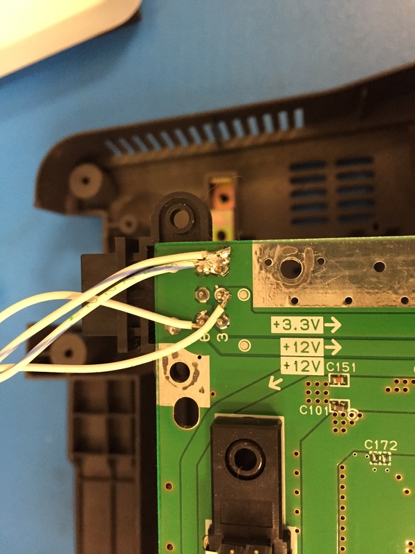
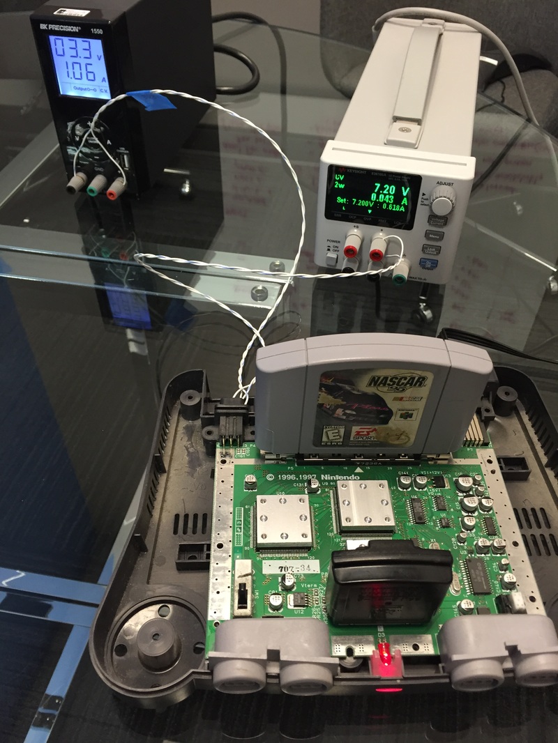
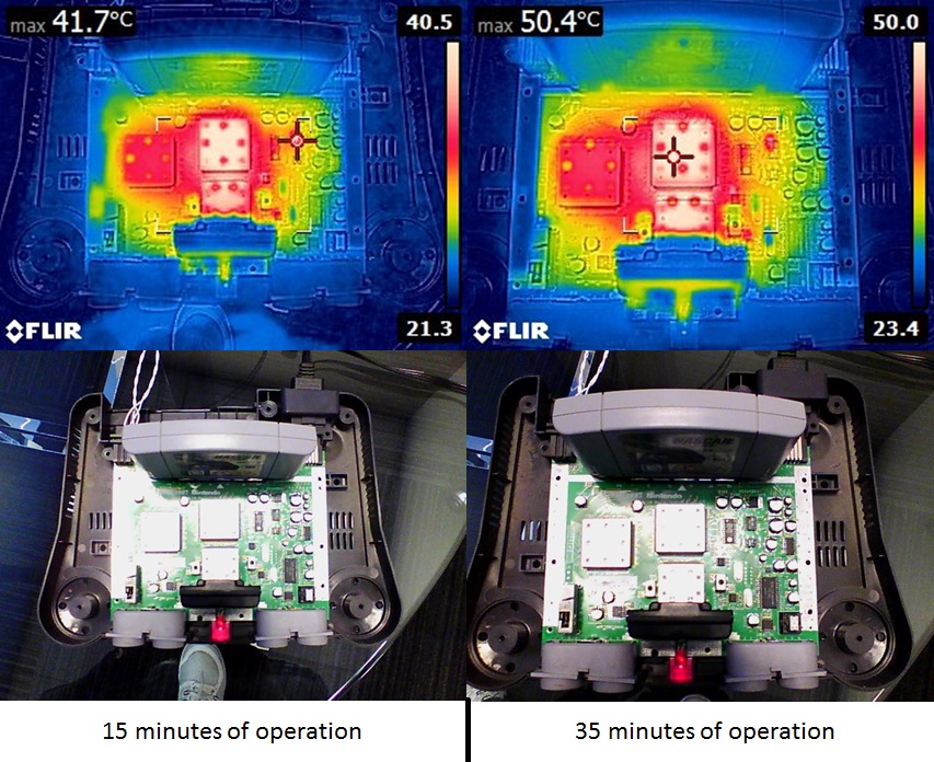
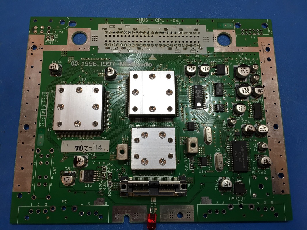
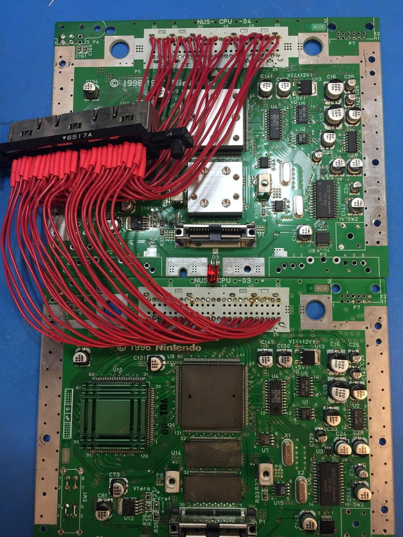
Very excited to get back into it after about a week of down time. Took apart the new unit and hooked up wires for the power connector since I don't have the power module that plugs into the back of the console so powering it off of two power supplies. initial test worked so the unit is healthy. I took FLIR readings of the heatsinks that came with the unit to get an idea of how much heat the fans are gonna need to cool down inside the case. In an ambient room that's ~23 deg C with still air the hottest parts of the N64 reach ~50 deg C. Rise of 30 deg C is a bit much but can't do much about it, just be cognizant.
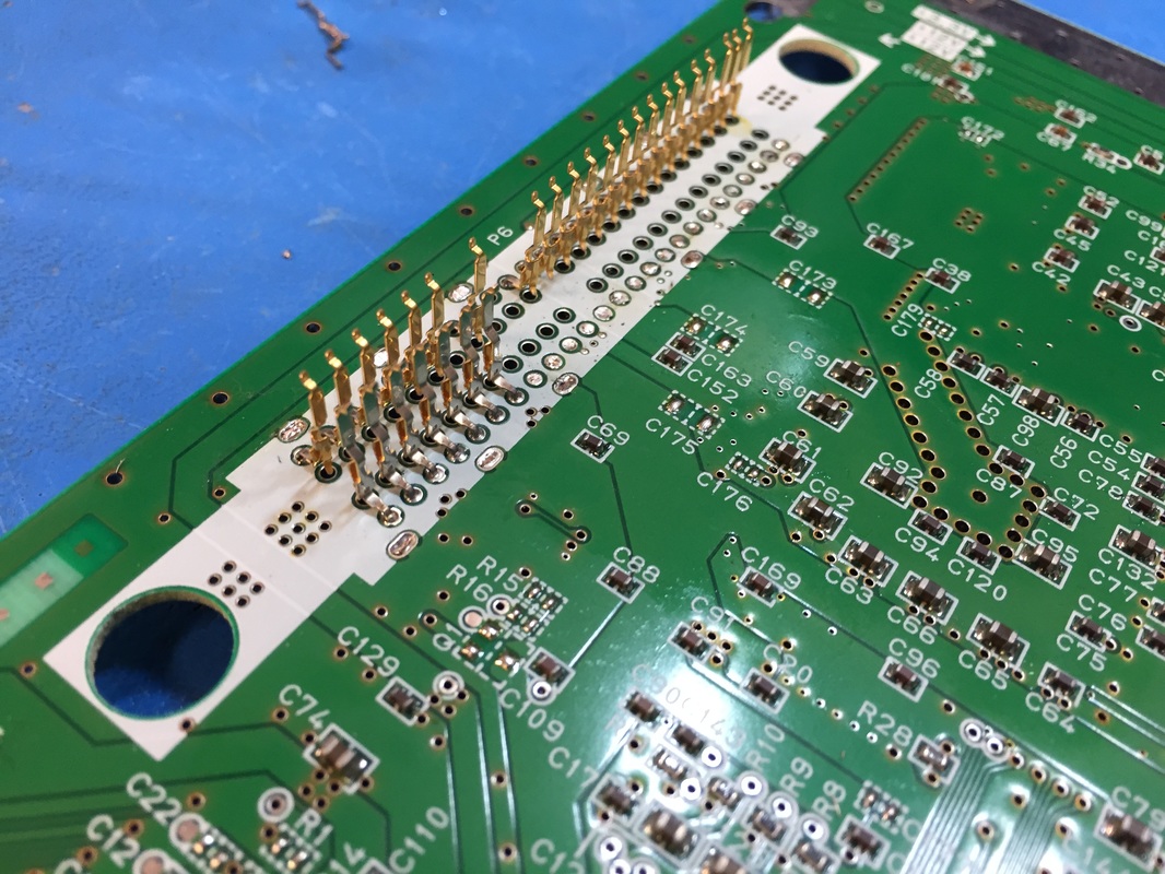
I proceeded with desoldering all the connectors and stuff. Not sure if I noted how to desolder the cartridge easily last time. There are metal tangs around the perimeter that keep the shield grounded. You can cut those from the top connector and slip the whole connector out, the connector that holds your cartridge is not soldered down through the pins, just those metal grounding tangs. Then around the bottom side, the expansion pack connector can be slid off in the same way, the plastic connector housing will come off leaving the metal contact soldered down. Then you can go through and desolder each one very easily.
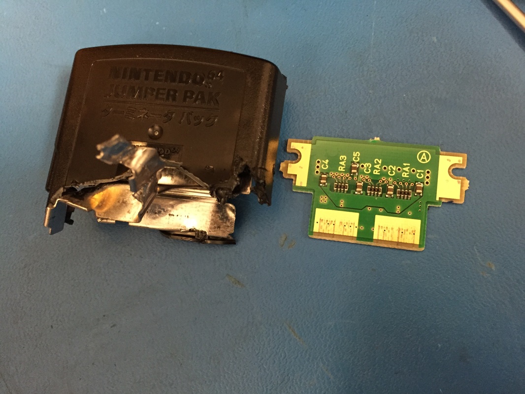
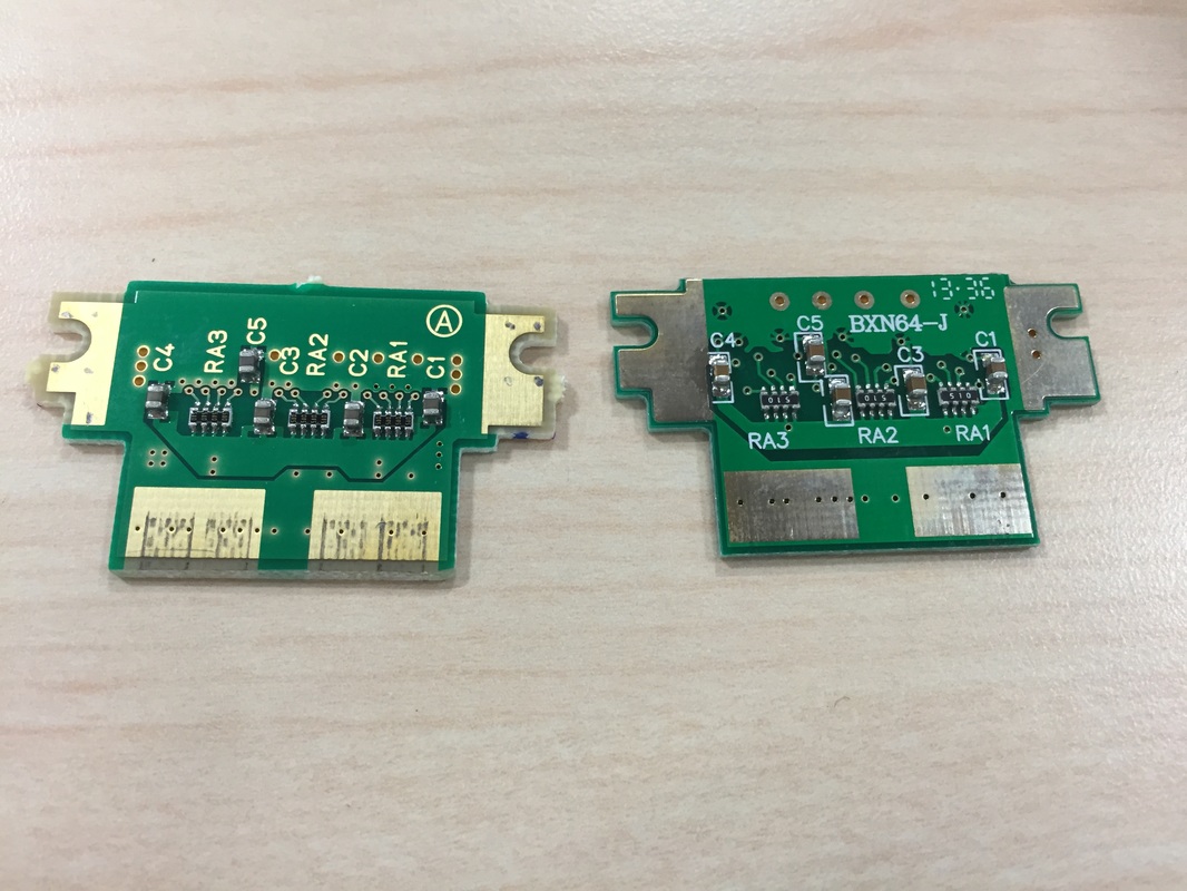
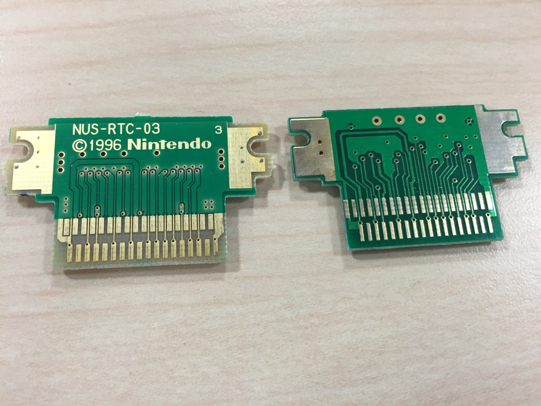
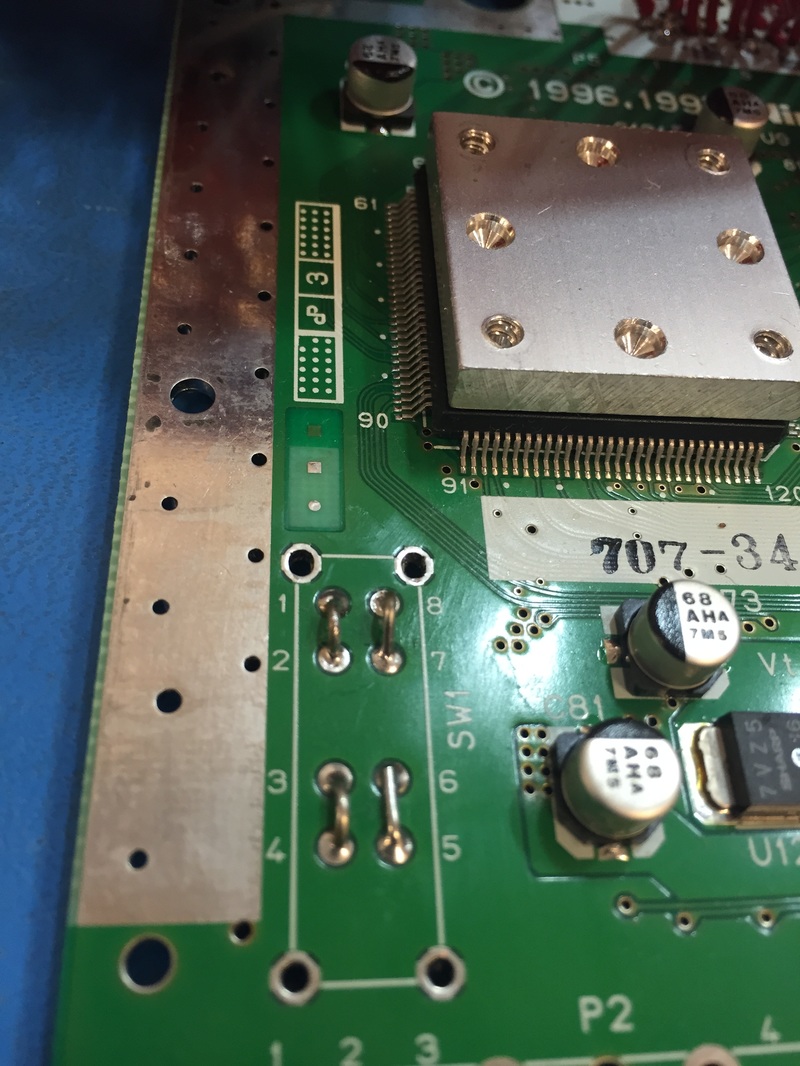
I didn't have the screwdriver for the jumper back so had to break the case. Seems like the one that came with this new N64 is made by Nintedo (original N64 I bought didn't have that writing... maybe it was counterfeit or cheap knock off?)
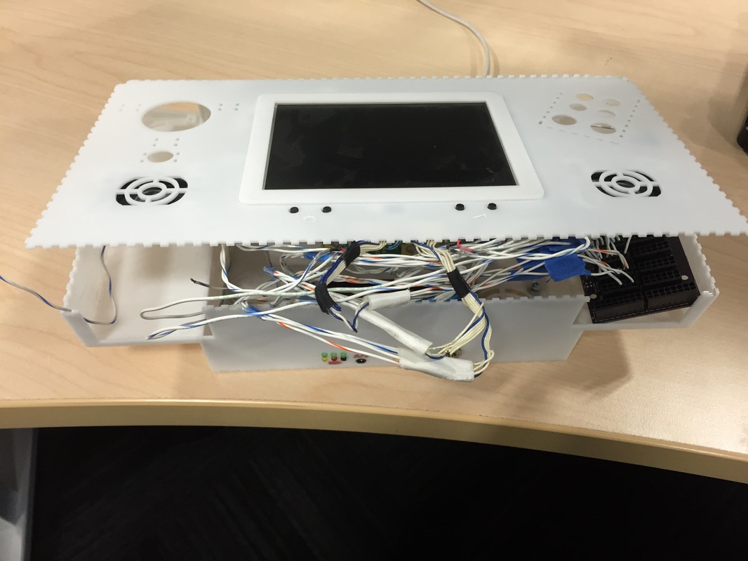
Very excited to get back into it after about a week of down time. Took apart the new unit and hooked up wires for the power connector since I don't have the power module that plugs into the back of the console so powering it off of two power supplies. initial test worked so the unit is healthy. I took FLIR readings of the heatsinks that came with the unit to get an idea of how much heat the fans are gonna need to cool down inside the case. In an ambient room that's ~23 deg C with still air the hottest parts of the N64 reach ~50 deg C. Rise of 30 deg C is a bit much but can't do much about it, just be cognizant.
I proceeded with desoldering all the connectors and stuff. Not sure if I noted how to desolder the cartridge easily last time. There are metal tangs around the perimeter that keep the shield grounded. You can cut those from the top connector and slip the whole connector out, the connector that holds your cartridge is not soldered down through the pins, just those metal grounding tangs. Then around the bottom side, the expansion pack connector can be slid off in the same way, the plastic connector housing will come off leaving the metal contact soldered down. Then you can go through and desolder each one very easily.
I didn't have the screwdriver for the jumper back so had to break the case. Seems like the one that came with this new N64 is made by Nintedo (original N64 I bought didn't have that writing... maybe it was counterfeit or cheap knock off?)
Rework
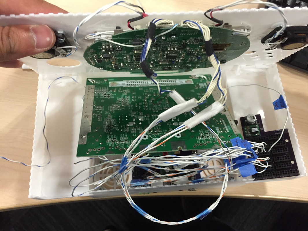
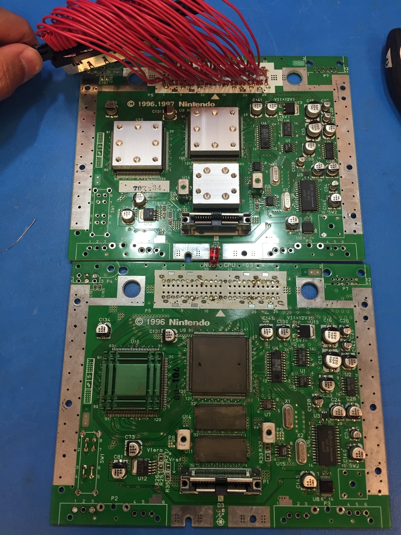
With the N64 board cleaned and nudered of connectors I went through each wire of the cartridge connector and transferred from old N64 to new N64. Pretty simple job, some wires were a bitch because you can't heat it up to much or else you'll melt the plastic insulation but the ground contacts can really sink some heat!. Tested the unit again and it all works, no mistakes made. Hope I don't have to do that again...
With the N64 board cleaned and nudered of connectors I went through each wire of the cartridge connector and transferred from old N64 to new N64. Pretty simple job, some wires were a bitch because you can't heat it up to much or else you'll melt the plastic insulation but the ground contacts can really sink some heat!. Tested the unit again and it all works, no mistakes made. Hope I don't have to do that again...
Back to debugging PCB
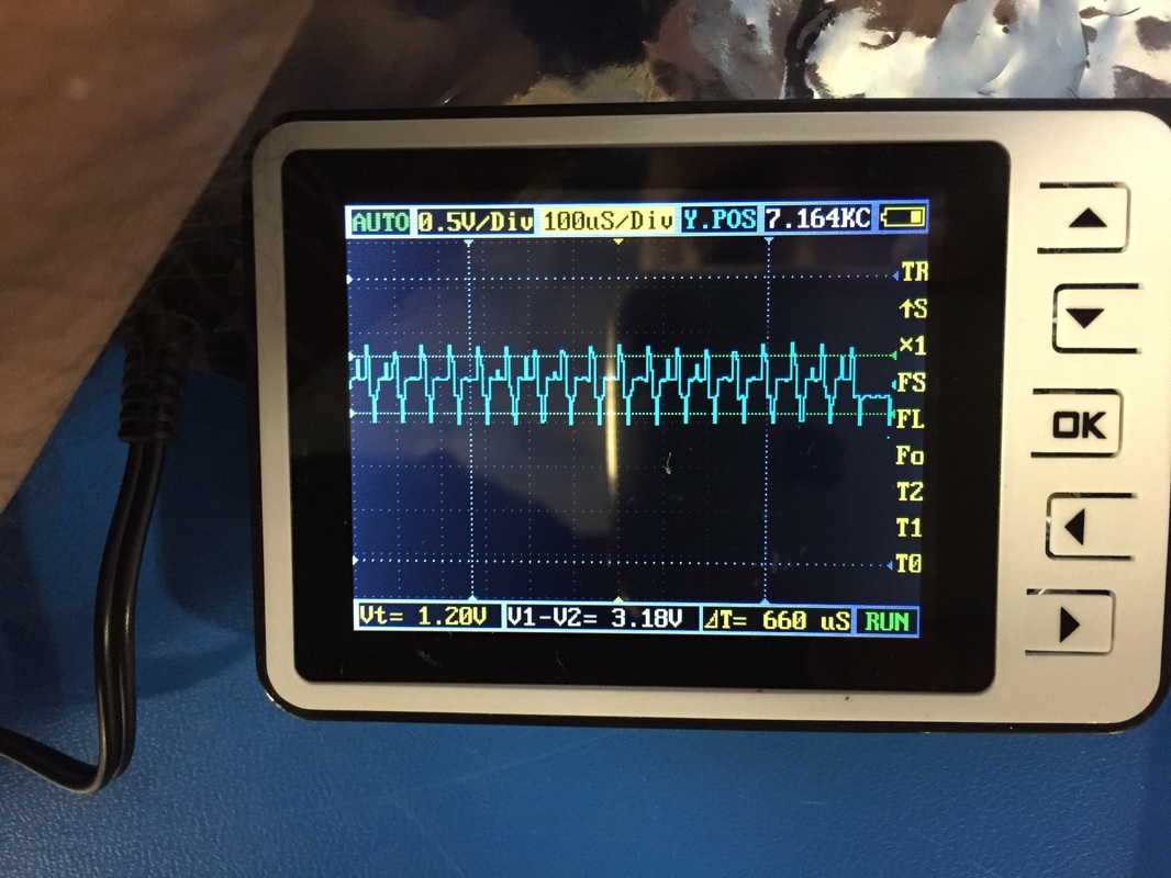
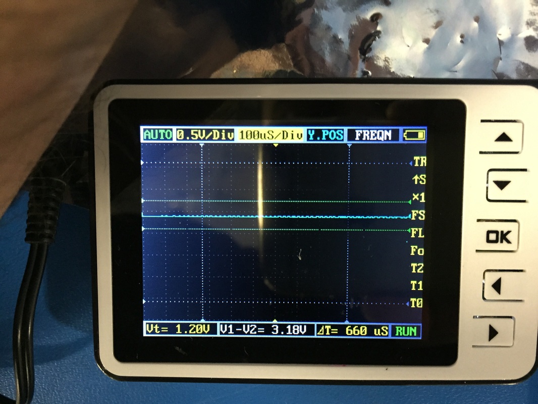
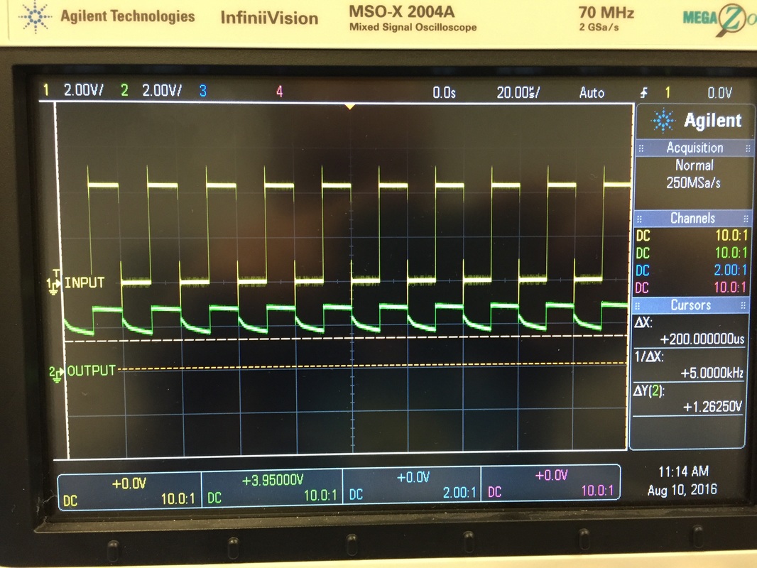
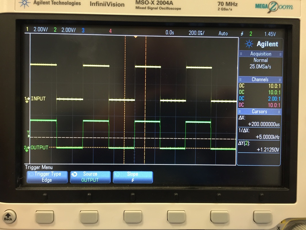
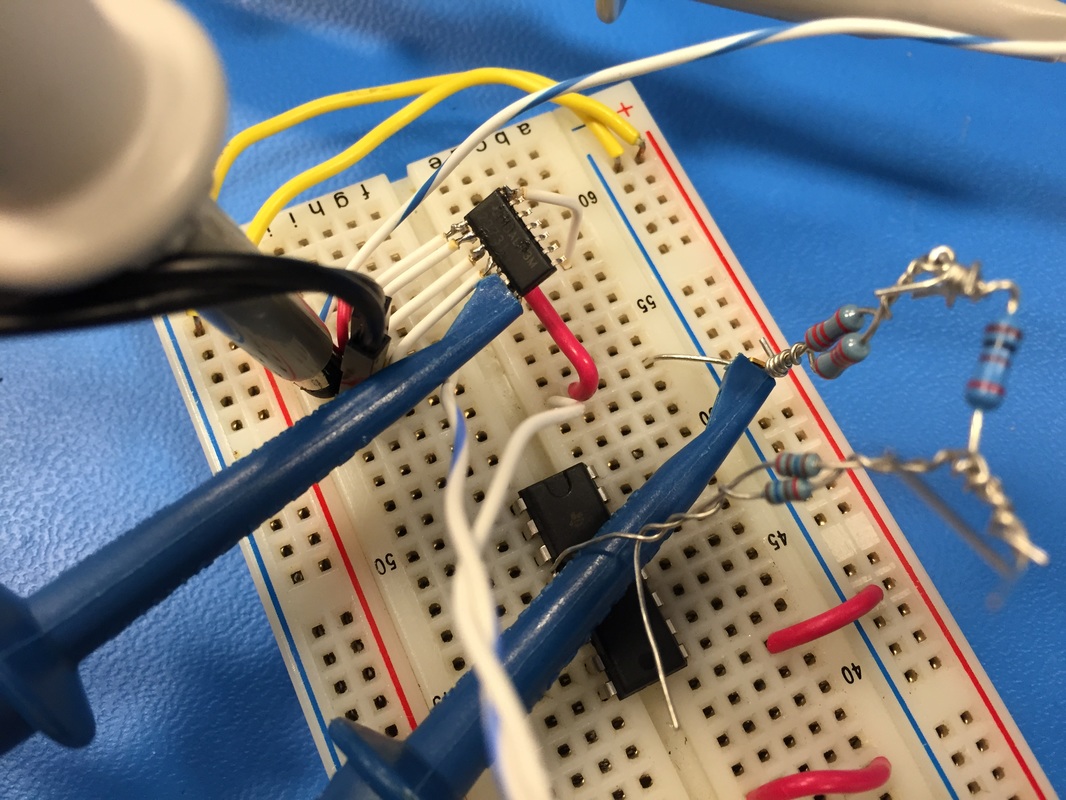
You can see the composite video signal in the first picture, I'm looking at this on U2 pin 3. But when I try to see the output of that first opamp on U2 pin 1 the signal is not there (picture 2). After a lot of headache and looking at the datasheet for the opamp (TLV2373) it seems that the shutdown pin can't quite stay high if left floating. The datasheet explicitly says that if left floating or tied high the opamp works but that is not the case and it needed to be tied high. So I jerry-rigged another clone of the opamp on a breadboard and fed in a square-wave with the DSO nano v2, You can see in picture 4 that if the shutdown pin is not explicitly tied high the output does weird non-opamp stuff, but picture 5 is the opamp clearly acting as an opamp when the shutdown pin is pulled high.
After I wight-wired the shutdown pins high on the main PCB I hooked it up to the N64 and screen to see if the whole thing worked. I had to tweak a bunch of resistor values to get the correct control. So R17 was changed from 1k to 110k to really dampen and incoming signal. The starting screen output gave me a DC RMS of about 180mV with not too much pk-pk. With that R17 so high and the DC RMS at 180mV, the second stage amp had to be bumped from 3x to 10x so I replaced R18 from 2k to 9k. This ensured that I'll have a signal that's above 0.6V for the transistor to turn on. Lastly, I changed R20 from 1k to 110k so that the output signal was filtered and did not flutter to fast. One problem I was having after changing R17 was that times when the screen was dark the signal was so low (around 90mV) that the screen was being turned off. So had to amplify and filer just right to not have the screen turn off even if there isn't much activity on the screen because a black screen is still a signal just a faint one. Sadly I didn't take any pictures of all this but testing it proved me right. I'd turn on the console and the screen was on, would plug in the A/V jack and the screen would shut off. I even tried it with no game and the screen was on when the jack wasn't connected and off when it was so my circuit correctly told the difference between a blank screen and a black screen.
Onward
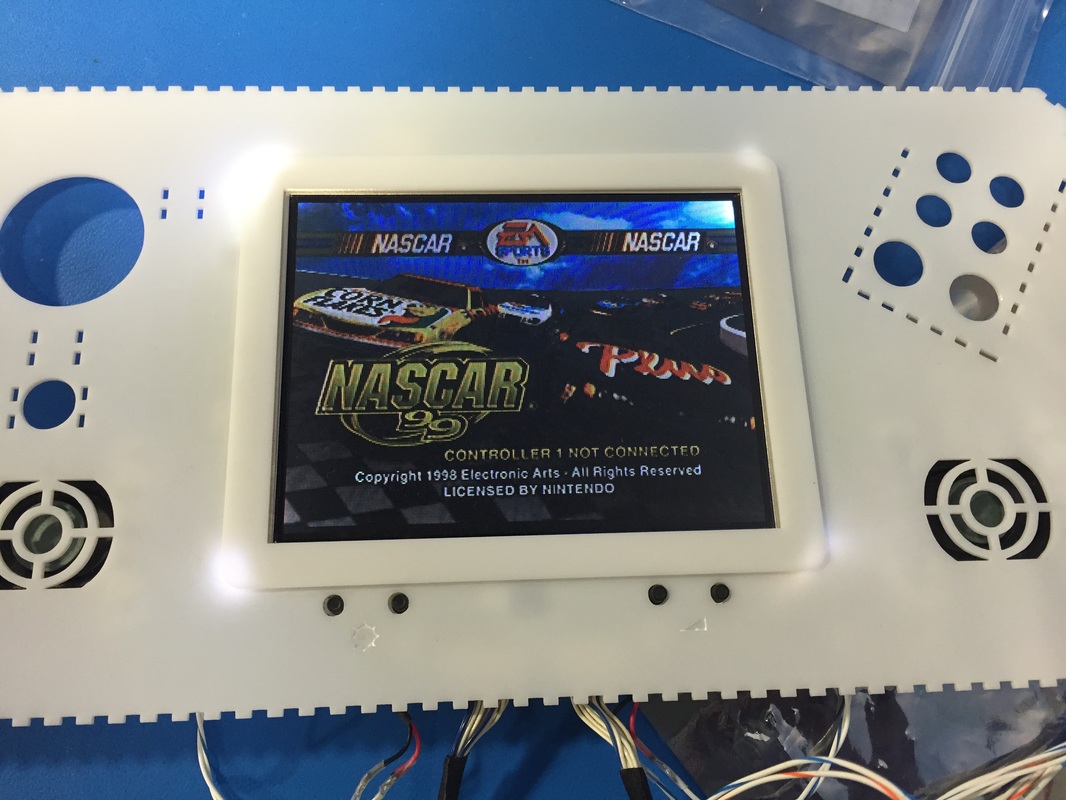
I tested the full unit with a range of voltages, found out that the screen starts to be squirrely around 6.8v so I adjusted the battery indicator to turn off the last green light at 6.9v, turn off the second green light at 7.5v and first green light at 8.1v.
Now there is two things I can do: build battery holder brackets so I can start assembling stuff into the DTV case and do testing, or I could cut some acrylic and build a small jig to test the controller port fin so that the case doesn't break apart when someone uses the controller ports. Woohoo!