Test Box (DTV)
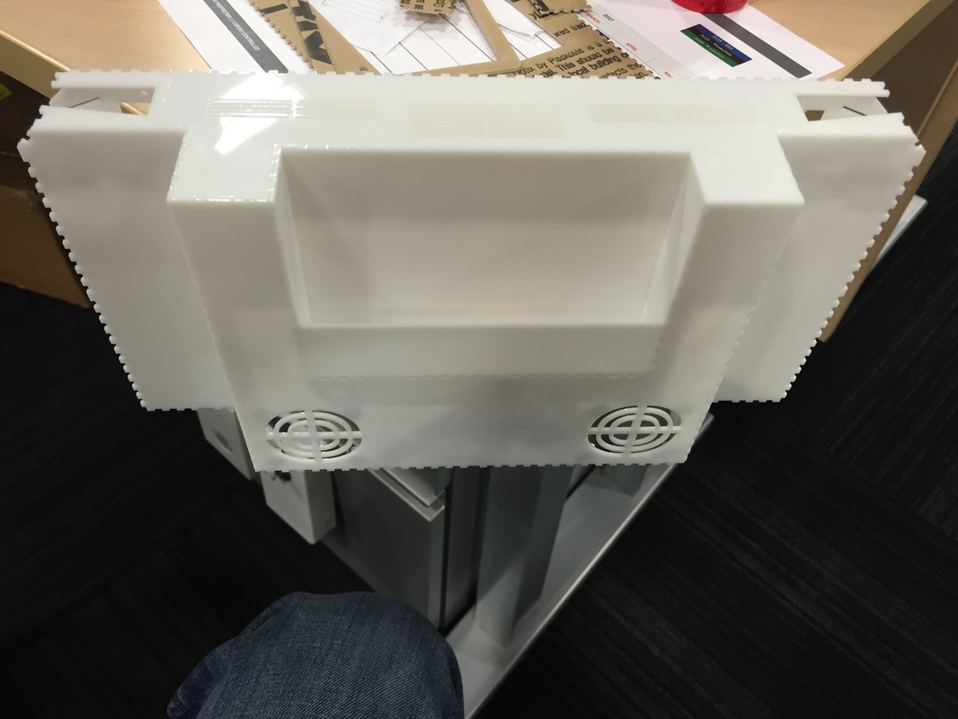
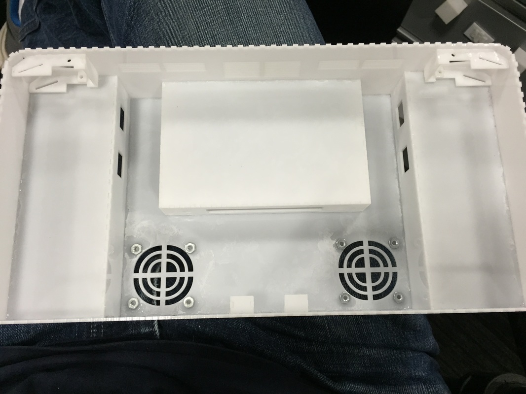
Decided that since I had a bunch of the parts already cut out, I'd go ahead and finish the 3D model translation to illustrator and cut out the remaining pieces I need. I tend to be very conservative with risk and having a "draft" case where I get to test stuff out is crucial. In the aerospace world we sometimes call this a Dynamic Test Vehicle (DTV) where you build the shell of a spacecraft and see if the structure holds during testing and fit checks.
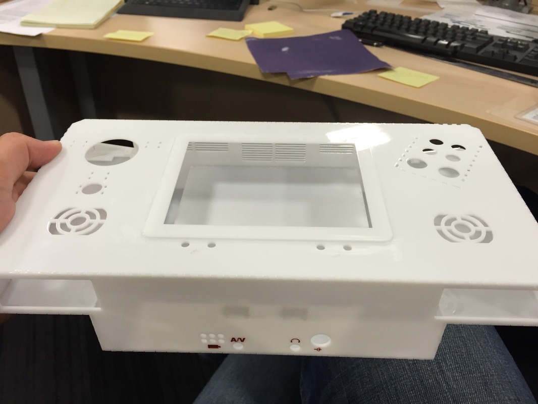
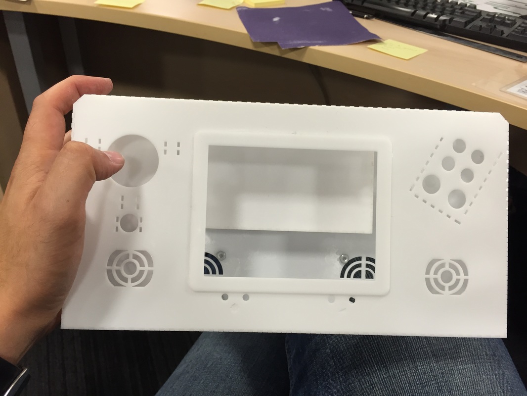
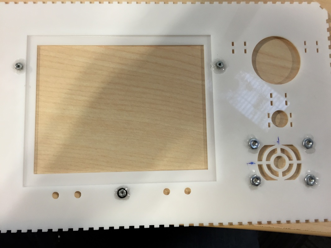
The build was pretty good, not a whole lot of problems, just had to figure out how to set stuff down as the glue cured. The faceplate is not glued as it will be held on by friction and magnets. Some small parts in my illustrator file have to be redone since I made some mistakes in the translation. But mostly good. I'm gonna start mounting some stuff in here to see how well they mount and how hard gluing all the nuts on here are gonna be. The screen is already proving to be a pain in the ass to locate holes and glue.
I noticed a lot of glue vapor etchings around the interfaces. I think the possibility of me messing up is high and I don't want to take the chance of some vapor or glue smudge being on the case so I've decided to sand the whole case after assembly. I start out low at 80 grit then work up all the way to 800 grit in circular motions. This dull's the shiny white but is still really smooth to the touch and gives me a way to fix any mistakes during gluing.
Decided that since I had a bunch of the parts already cut out, I'd go ahead and finish the 3D model translation to illustrator and cut out the remaining pieces I need. I tend to be very conservative with risk and having a "draft" case where I get to test stuff out is crucial. In the aerospace world we sometimes call this a Dynamic Test Vehicle (DTV) where you build the shell of a spacecraft and see if the structure holds during testing and fit checks.
The build was pretty good, not a whole lot of problems, just had to figure out how to set stuff down as the glue cured. The faceplate is not glued as it will be held on by friction and magnets. Some small parts in my illustrator file have to be redone since I made some mistakes in the translation. But mostly good. I'm gonna start mounting some stuff in here to see how well they mount and how hard gluing all the nuts on here are gonna be. The screen is already proving to be a pain in the ass to locate holes and glue.
I noticed a lot of glue vapor etchings around the interfaces. I think the possibility of me messing up is high and I don't want to take the chance of some vapor or glue smudge being on the case so I've decided to sand the whole case after assembly. I start out low at 80 grit then work up all the way to 800 grit in circular motions. This dull's the shiny white but is still really smooth to the touch and gives me a way to fix any mistakes during gluing.
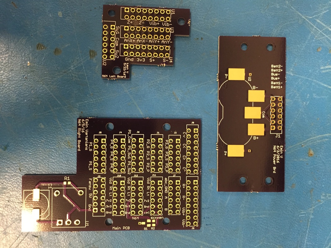
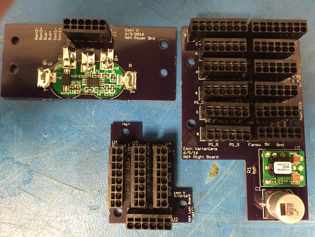
Printed Circuit Boards
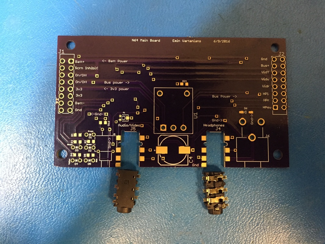
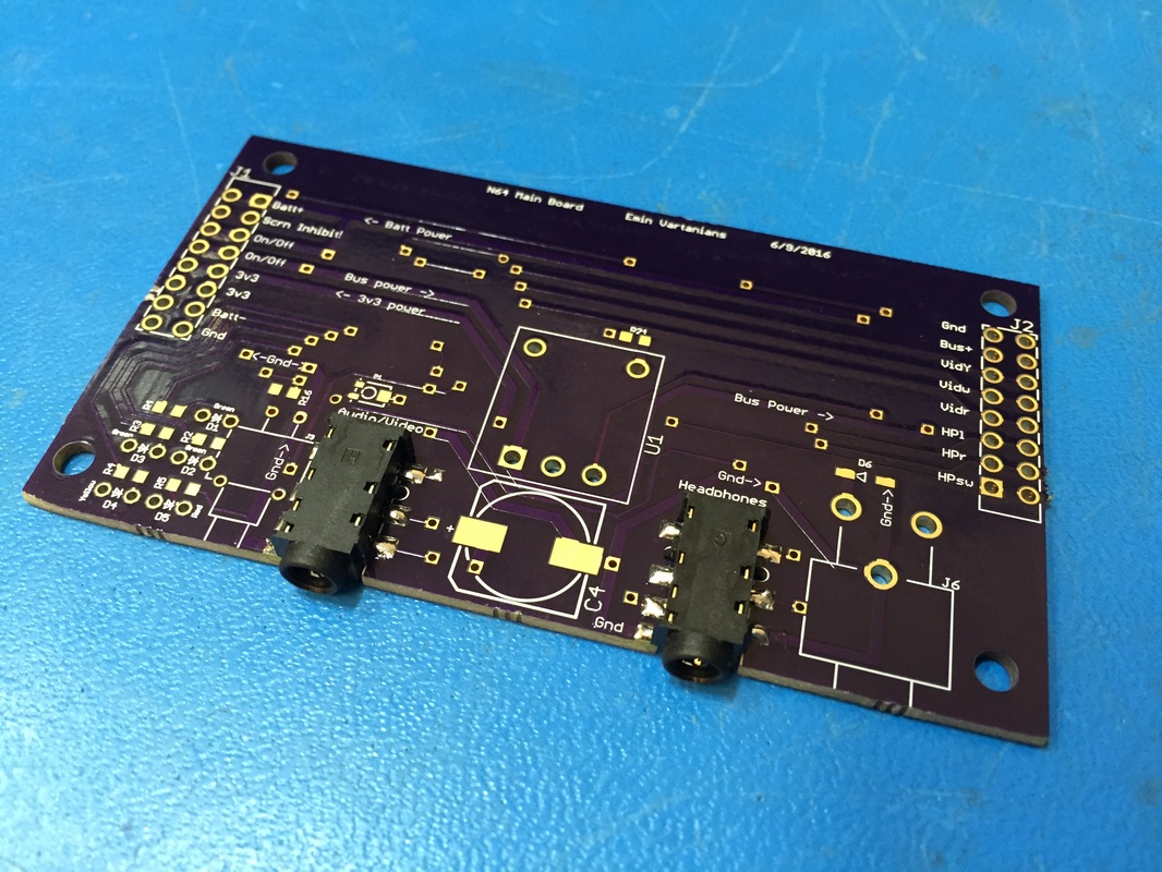
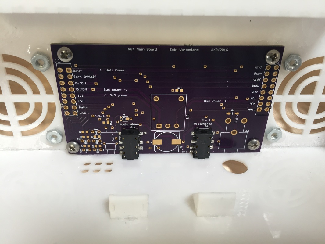
Got the PCB's in from OshPark and they are prettyyyyyyy. Populated the 3 easy PCB's and only did the 3.5mm jacks on the main PCB to make sure the solder pads were strong enough for me to plug in and out the connector. Haven't tested any of the boards yet, will need to do so before they get integrated.
Got the PCB's in from OshPark and they are prettyyyyyyy. Populated the 3 easy PCB's and only did the 3.5mm jacks on the main PCB to make sure the solder pads were strong enough for me to plug in and out the connector. Haven't tested any of the boards yet, will need to do so before they get integrated.
Bottom Panel Plugs
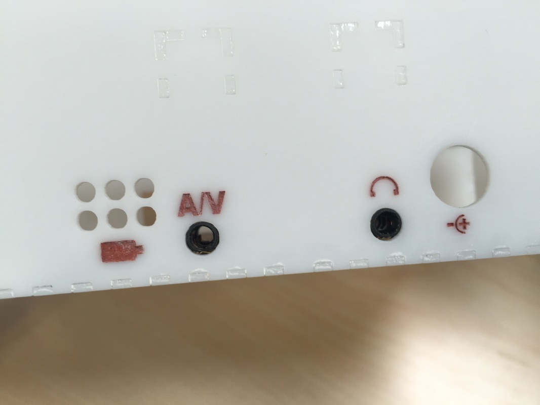
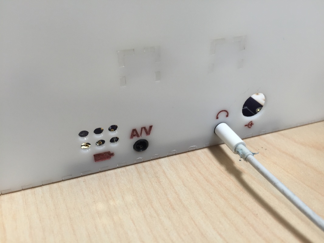
A big thing I worry about is if the glue holds for me to plug stuff in and out of the headphone/AV jacks, Battery charger, and multiplayer ports. The Headphone and A/V jacks were surprisingly strong. I mounted the PCB down on the inside of the back piece and screwed it down. The 3.5mm jacks are in the perfect place, the Battery charger port is a bit too large, my mistake in CAD, so gotta fix that for the final version.
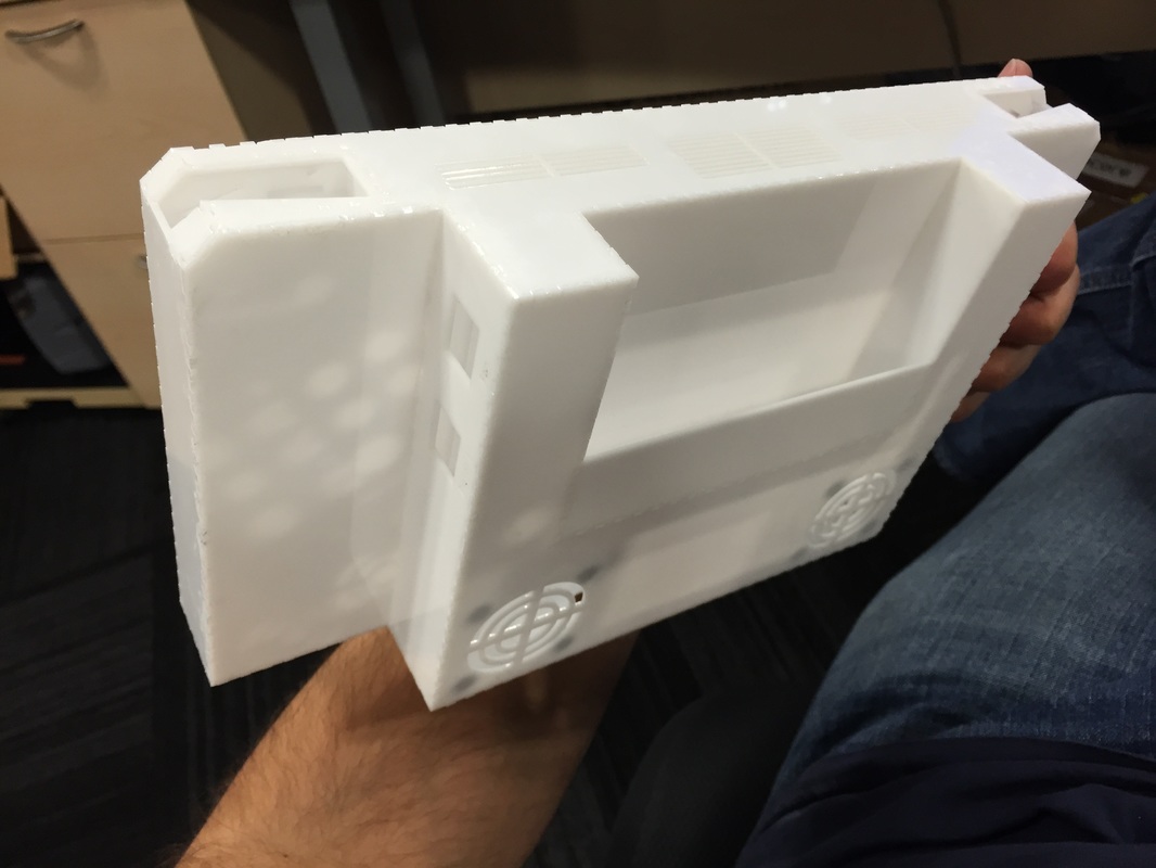
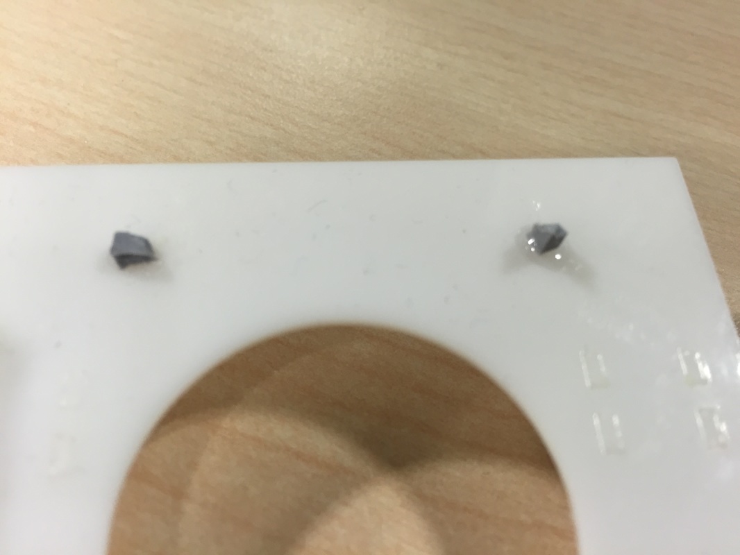
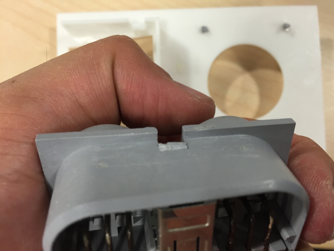
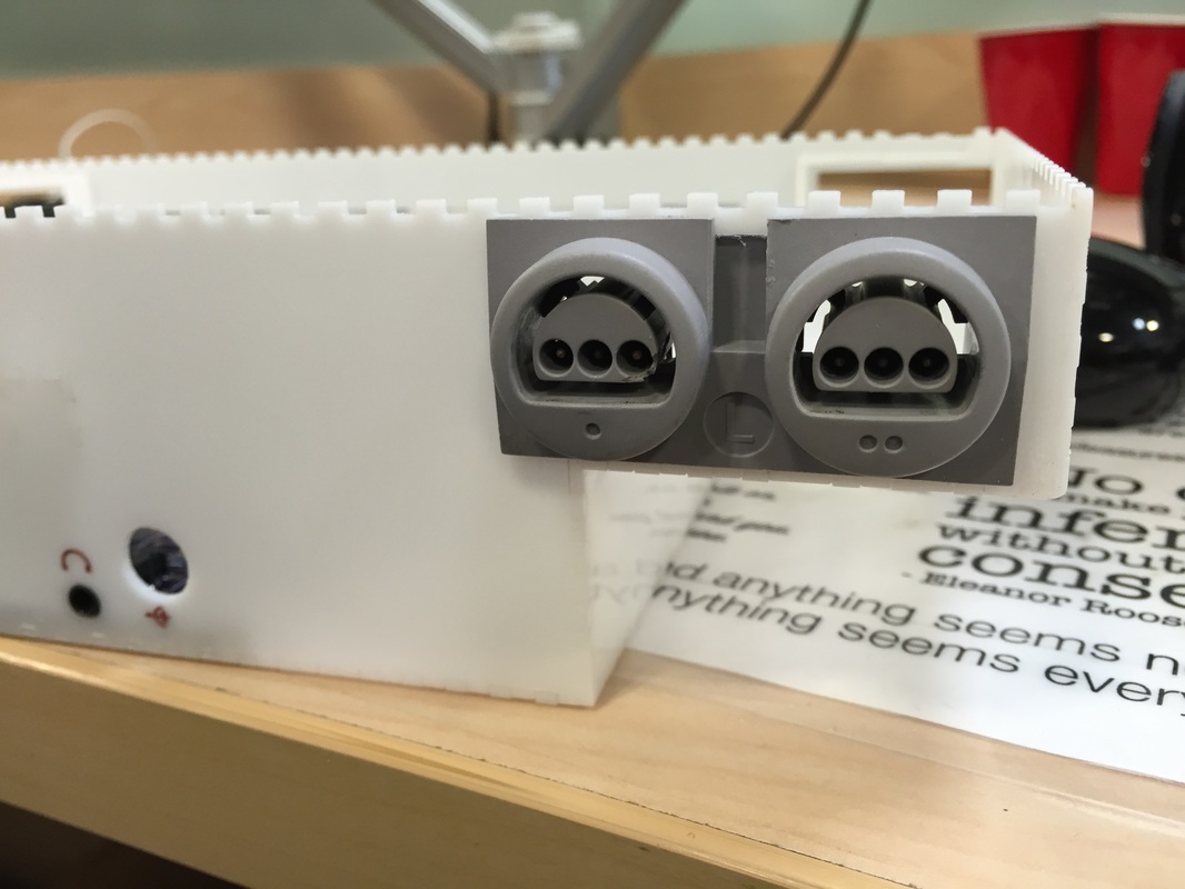
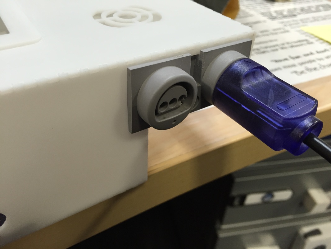
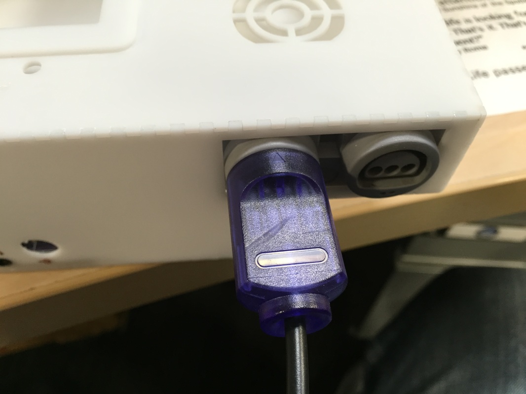
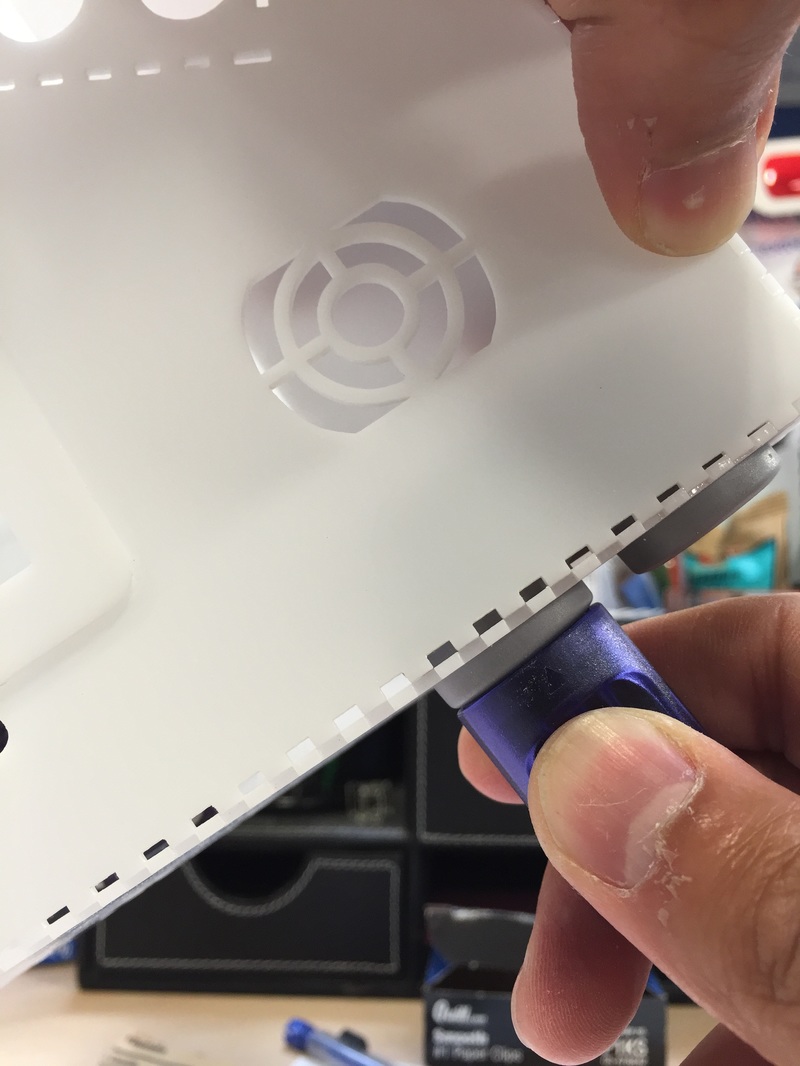
Was worried about the controller ports 1) gluing to the acrylic and 2) ripping the case as I plugged and unplugged. To get a better handle on the first worry I glued a couple small pieces of plastic I cut from the controller port onto a sample piece of acrylic. They hold beauitfully so I have faith in the controller port not separating from the panel. Next worry is that the panel will break apart. Since I only have one set of controller ports I can't glue these and find out, but if I position the port in the place (as seen in the 6th picture) I can test plugging it in. It wen't beautifully, no cracks, no sounds. Then I had to pull the controller out so I positioned the port behind the cutout inside the case (as seen in the 8th picture) and tried to pull it out. As you can see in the last picture the bottom piece bows out a bit to the point that I have to put my finger at the top of the port so it doesn't break. I think if I put a brace on the inside of the case running like a spine down the top of the case then It'll stiffen up that interface.
A big thing I worry about is if the glue holds for me to plug stuff in and out of the headphone/AV jacks, Battery charger, and multiplayer ports. The Headphone and A/V jacks were surprisingly strong. I mounted the PCB down on the inside of the back piece and screwed it down. The 3.5mm jacks are in the perfect place, the Battery charger port is a bit too large, my mistake in CAD, so gotta fix that for the final version.
Was worried about the controller ports 1) gluing to the acrylic and 2) ripping the case as I plugged and unplugged. To get a better handle on the first worry I glued a couple small pieces of plastic I cut from the controller port onto a sample piece of acrylic. They hold beauitfully so I have faith in the controller port not separating from the panel. Next worry is that the panel will break apart. Since I only have one set of controller ports I can't glue these and find out, but if I position the port in the place (as seen in the 6th picture) I can test plugging it in. It wen't beautifully, no cracks, no sounds. Then I had to pull the controller out so I positioned the port behind the cutout inside the case (as seen in the 8th picture) and tried to pull it out. As you can see in the last picture the bottom piece bows out a bit to the point that I have to put my finger at the top of the port so it doesn't break. I think if I put a brace on the inside of the case running like a spine down the top of the case then It'll stiffen up that interface.
Next Steps
I'll have to finish up the main PCB assembly and test out the boards individually. Then do an electrical connection test on all the interfaces. This will be just like the final assembly just not in the case. Once I know that all the electronics work I can focus back on the case. I've also Gotta cut that spine and retest the controller port real quick. Then assemble the battery holders and stuff so I can integrate stuff into the DTV. Once it all works I'll update the illustrator file and cut the whole kit one final time.
I'll have to finish up the main PCB assembly and test out the boards individually. Then do an electrical connection test on all the interfaces. This will be just like the final assembly just not in the case. Once I know that all the electronics work I can focus back on the case. I've also Gotta cut that spine and retest the controller port real quick. Then assemble the battery holders and stuff so I can integrate stuff into the DTV. Once it all works I'll update the illustrator file and cut the whole kit one final time.
