Integration
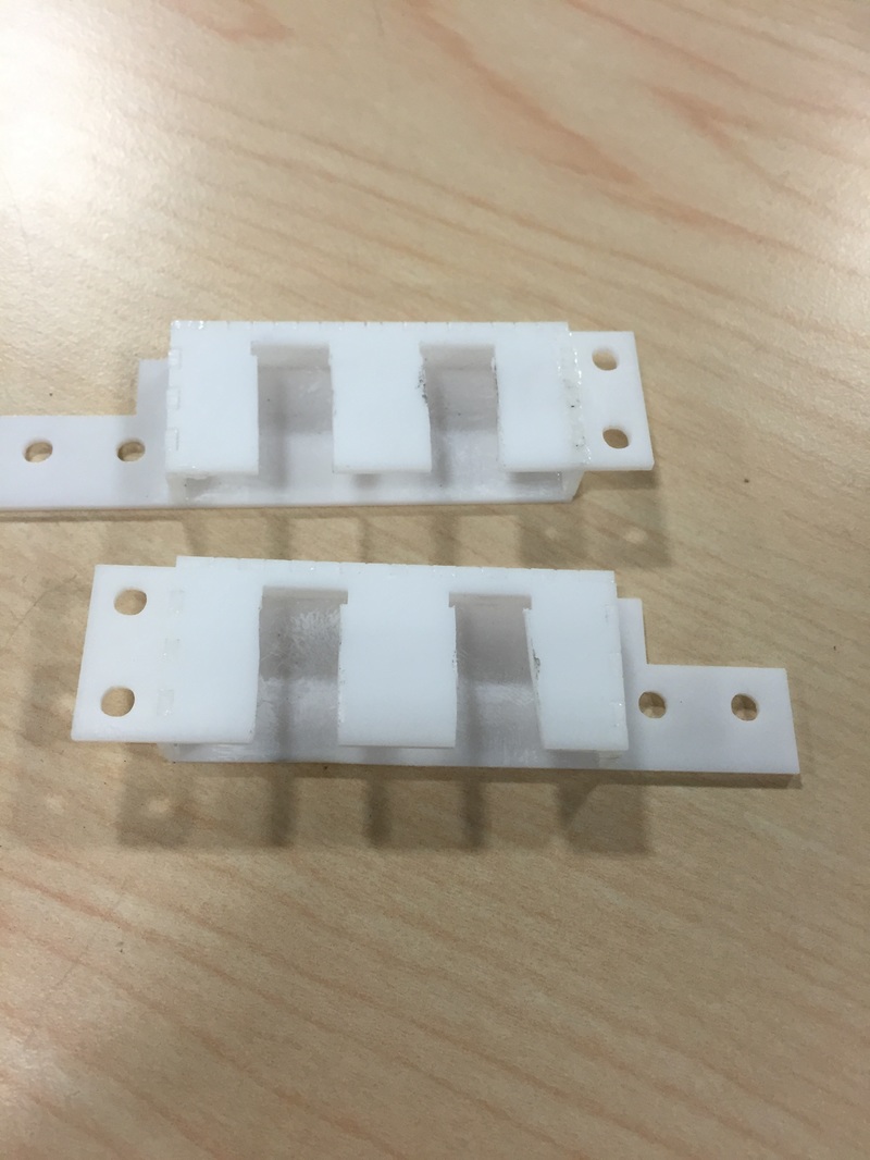
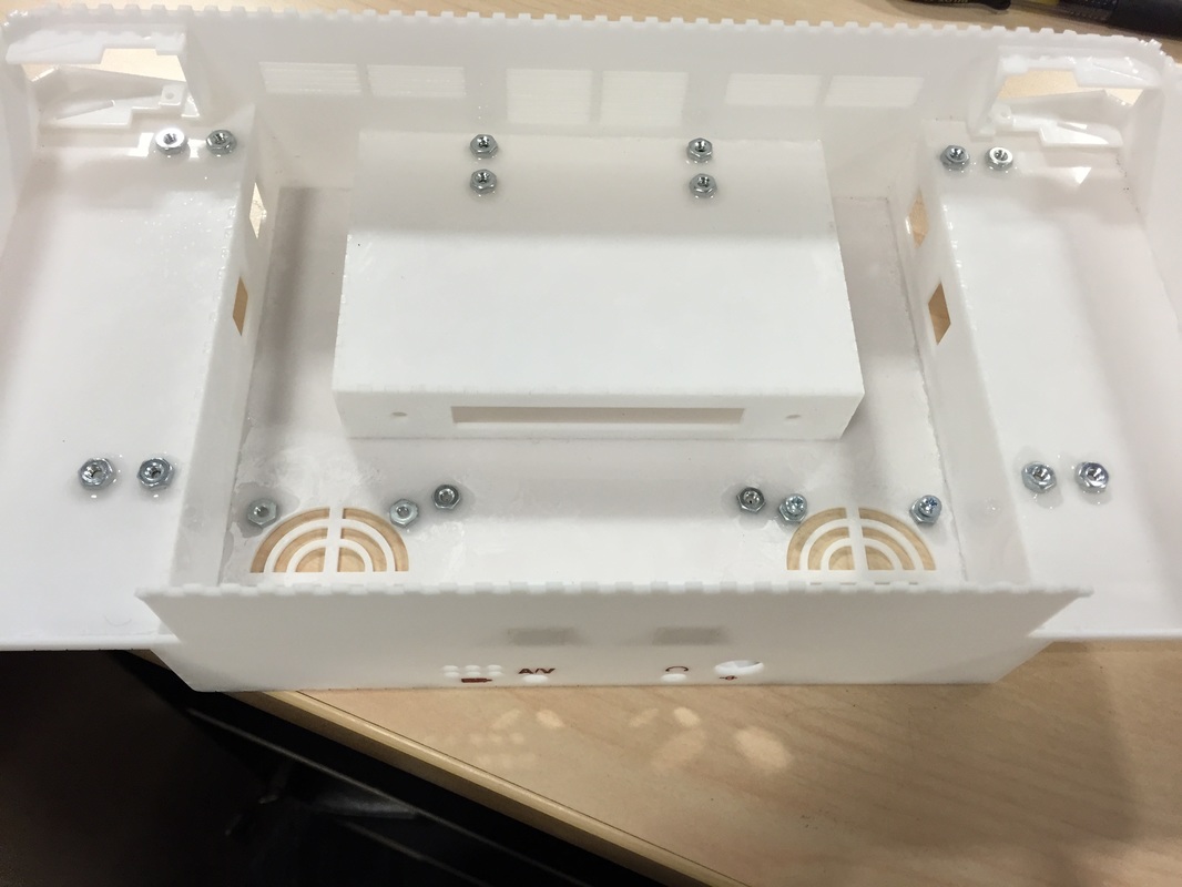
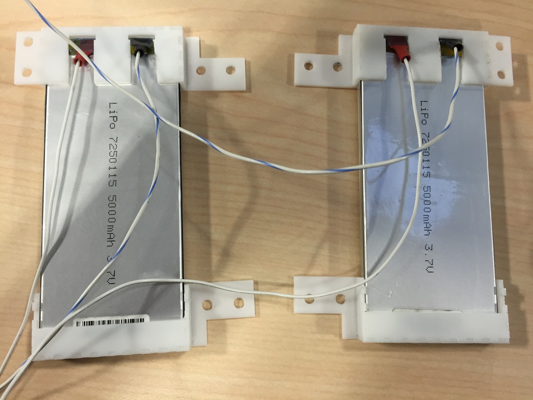
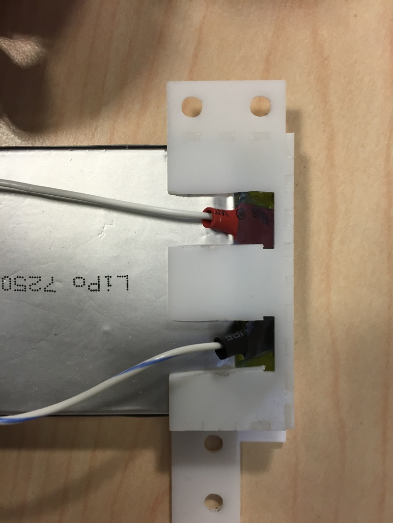
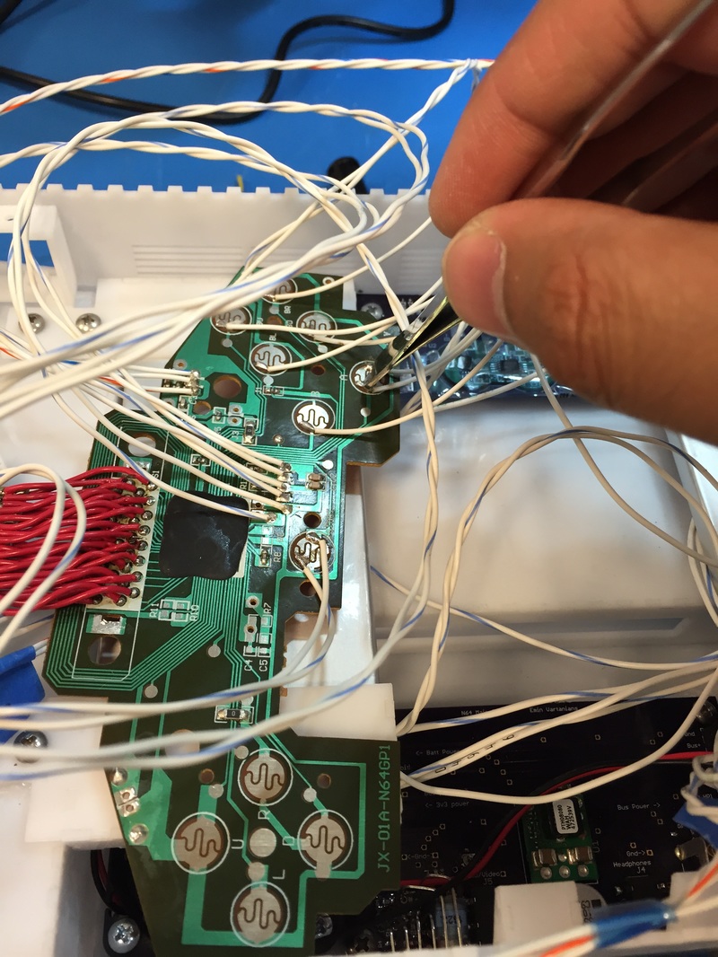
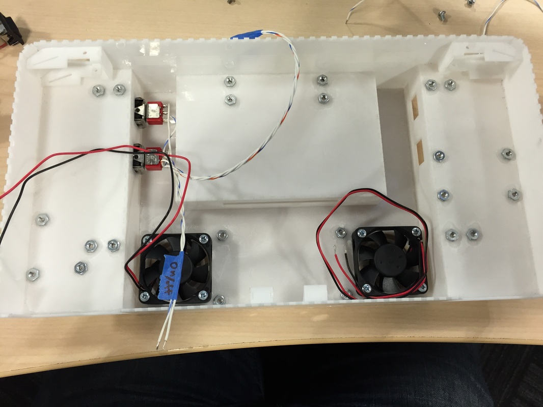
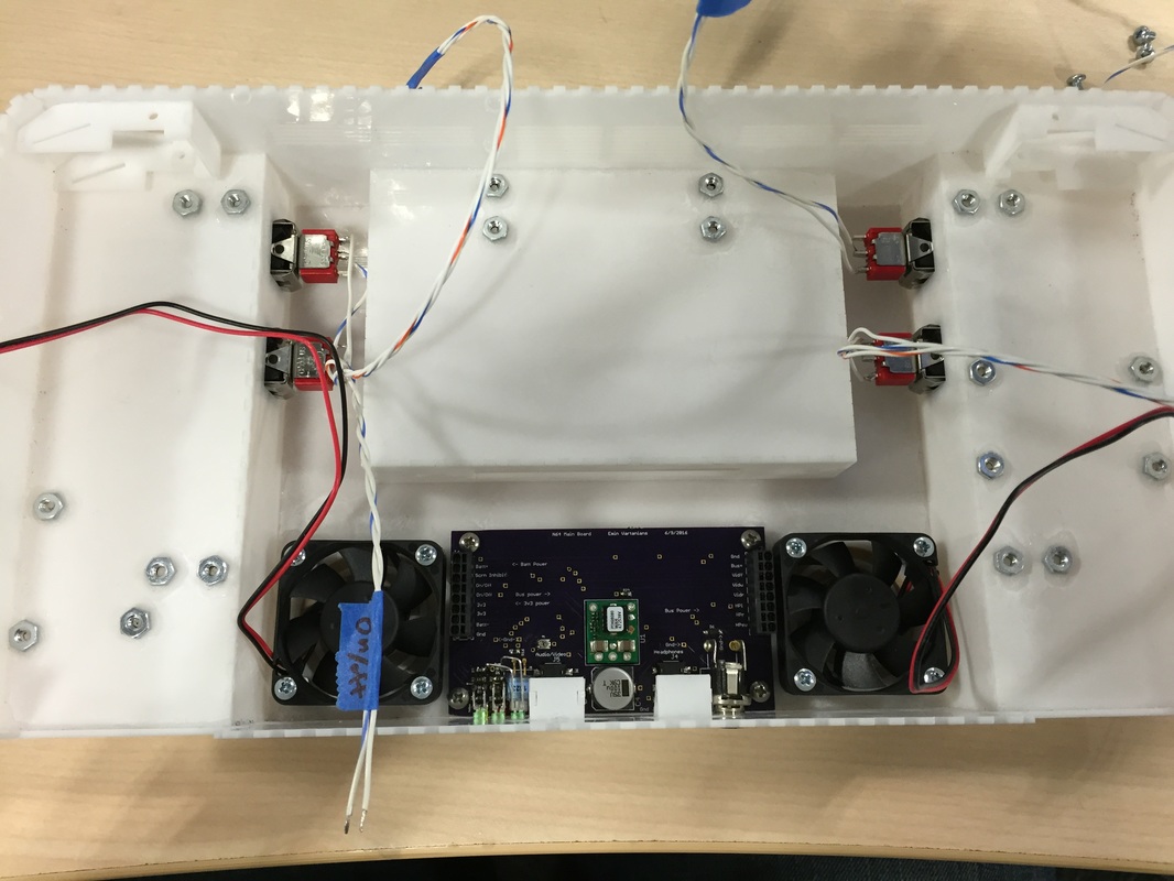
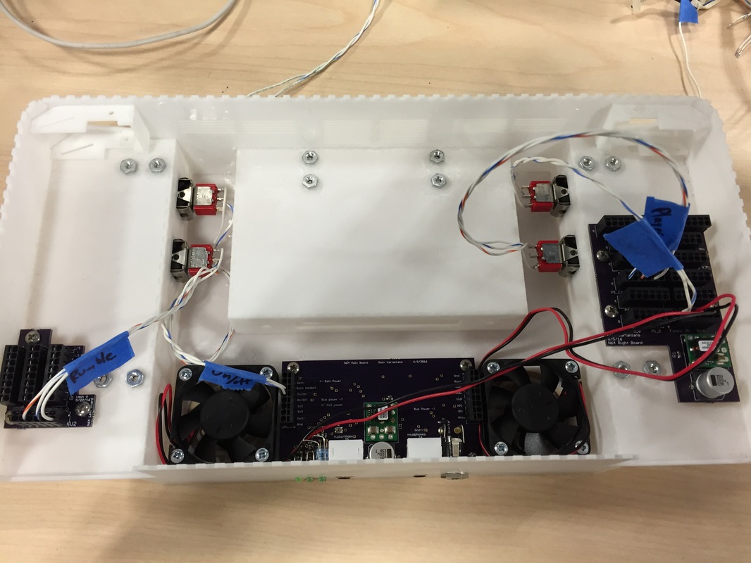
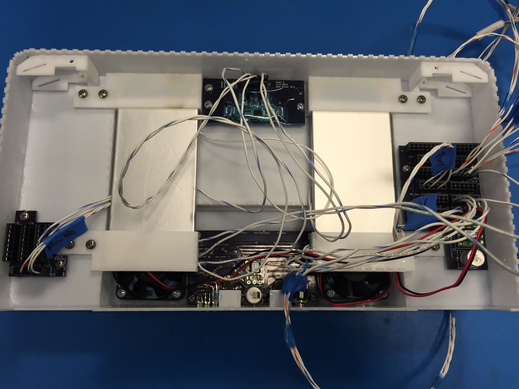
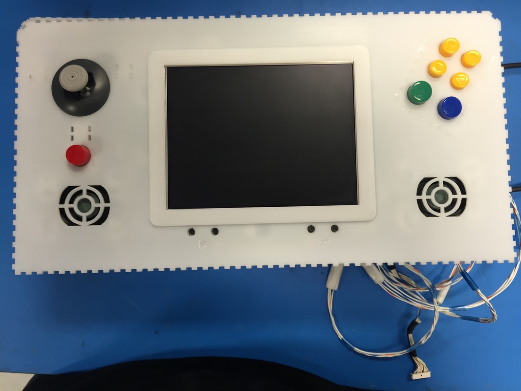
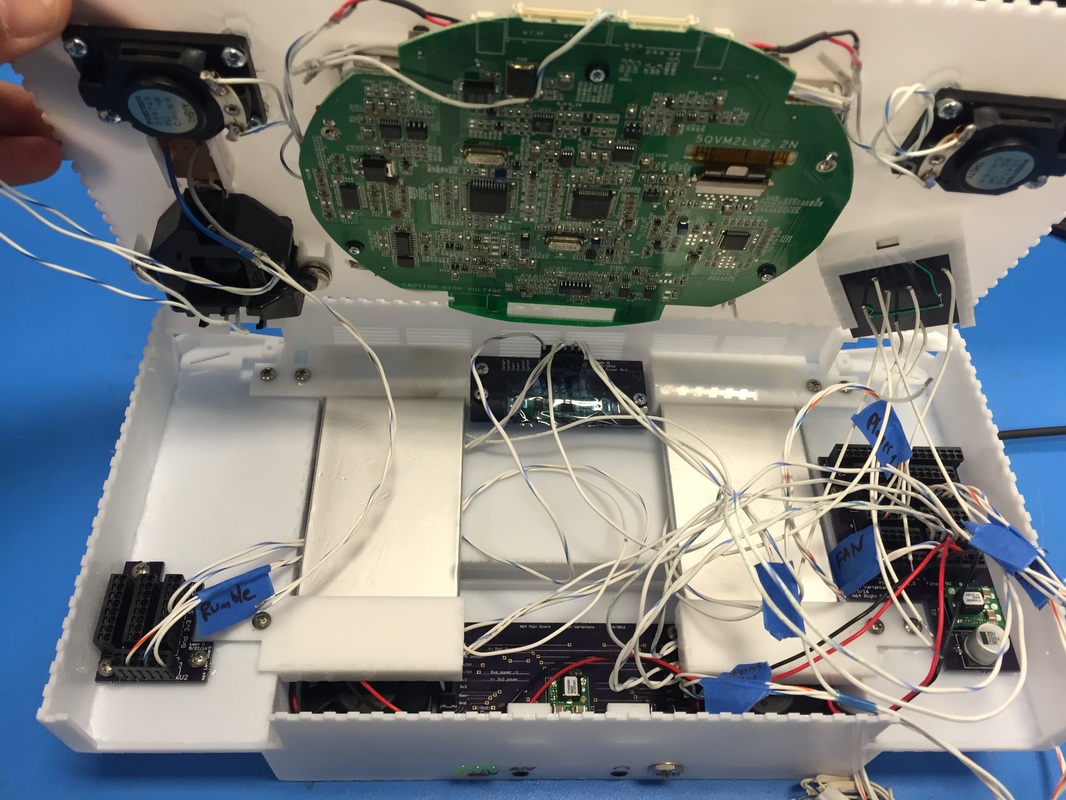
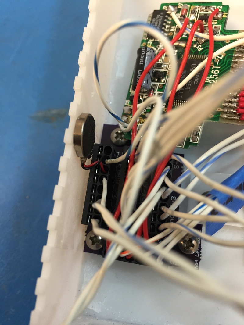
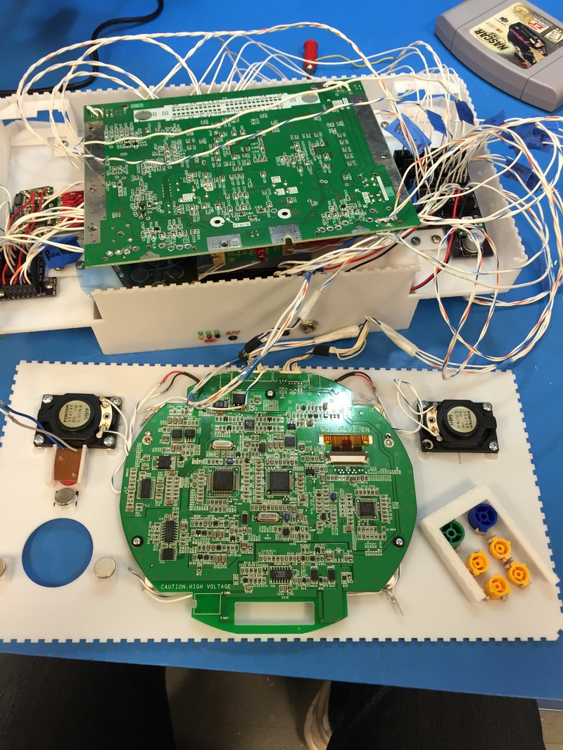
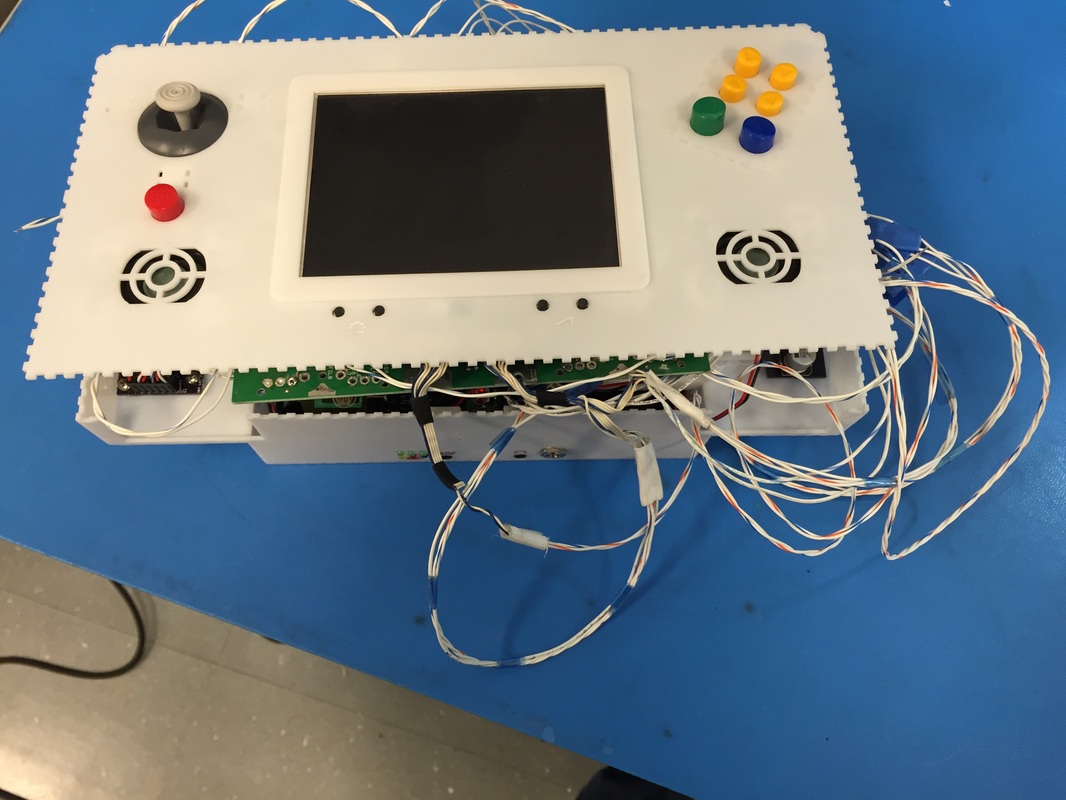
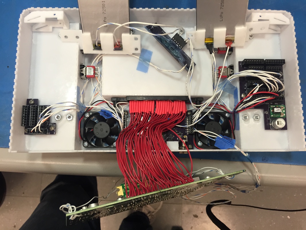
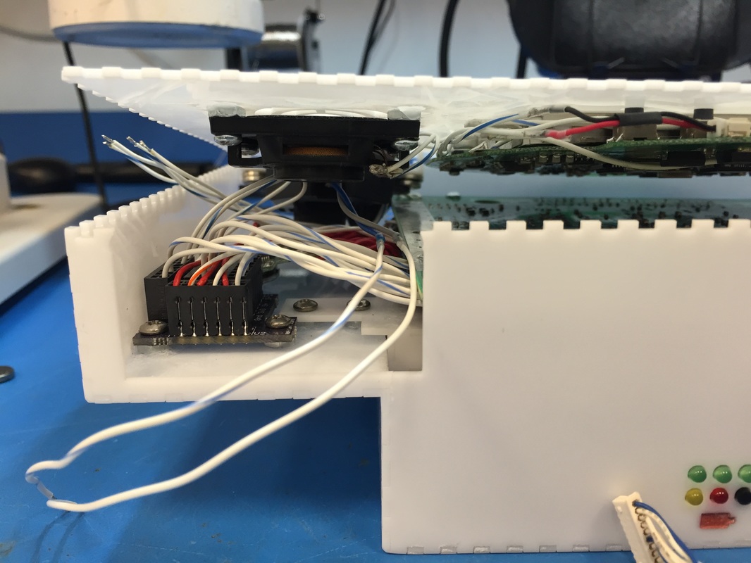
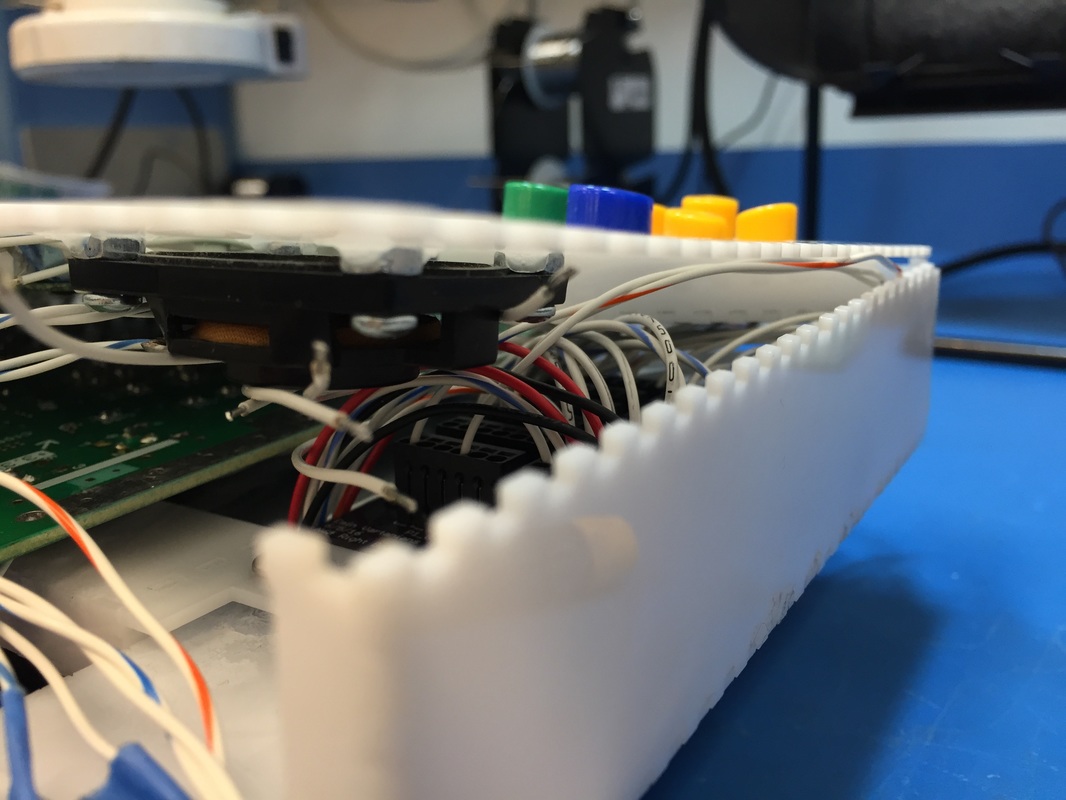
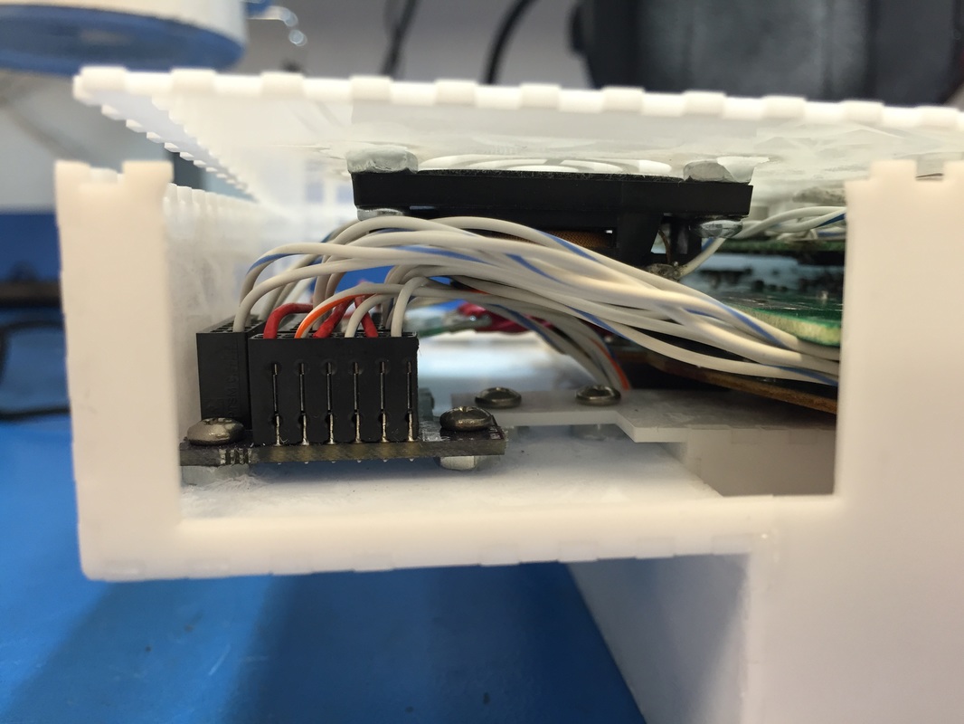
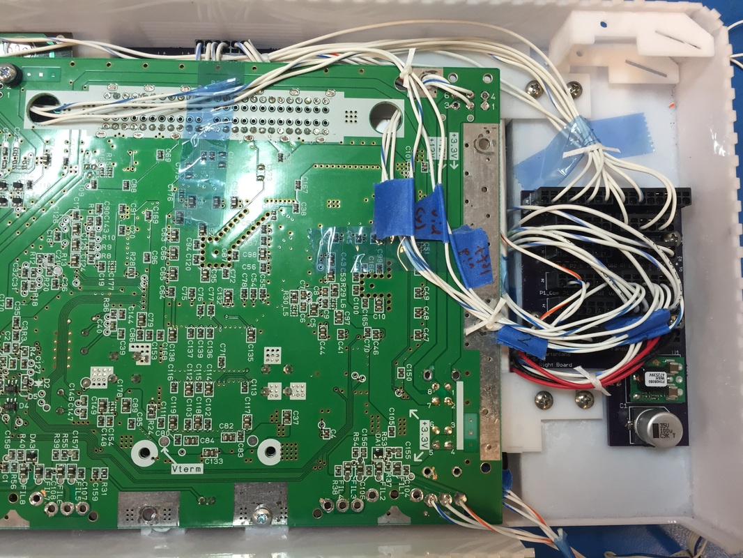
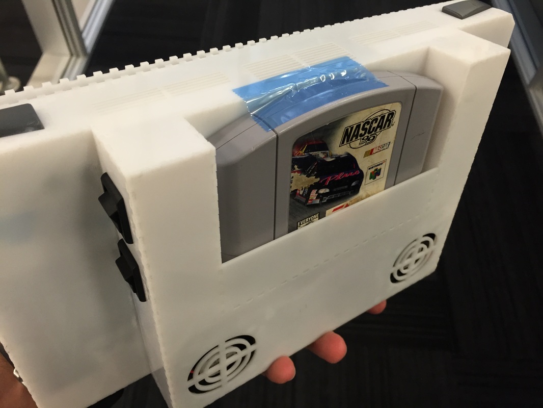
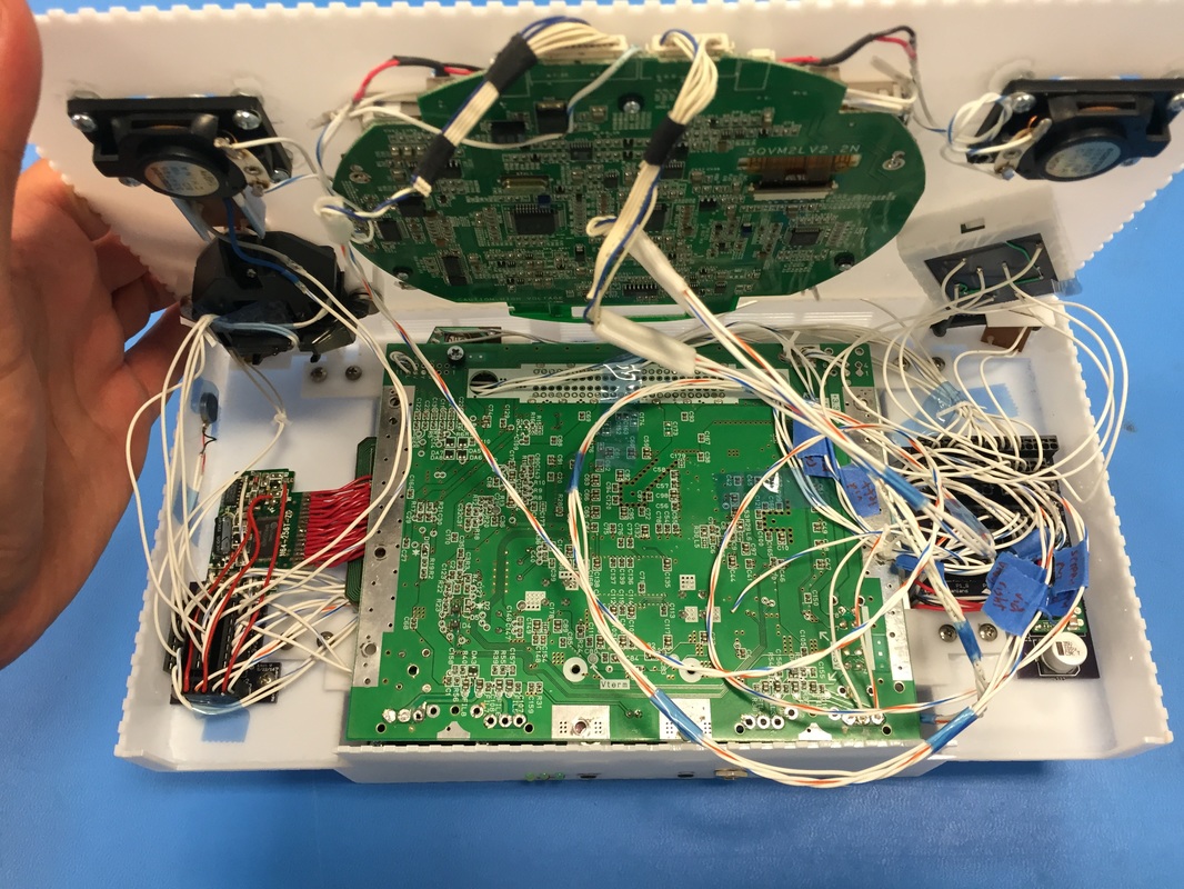
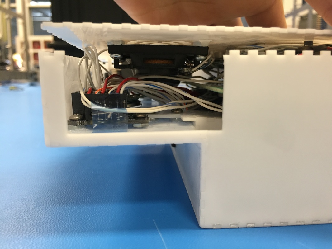
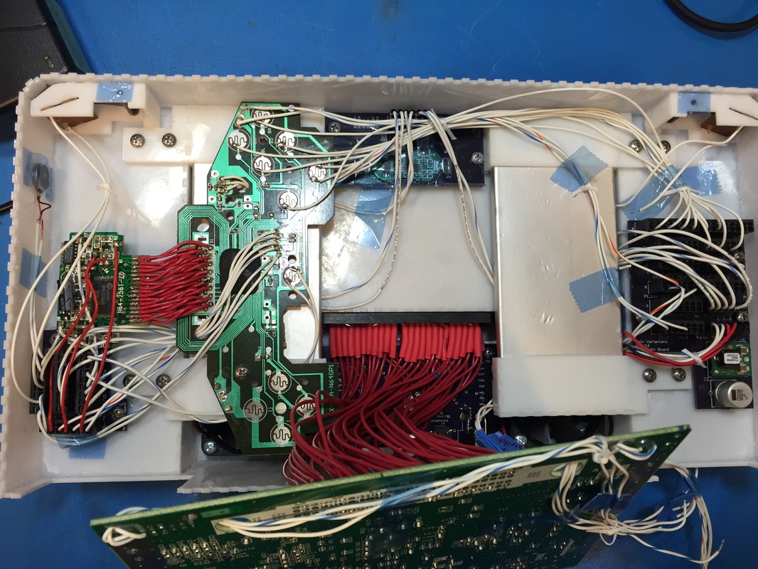
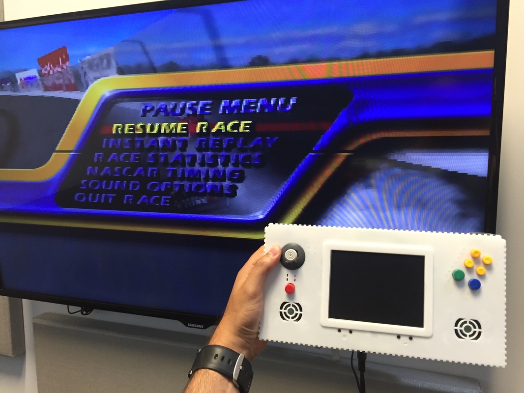
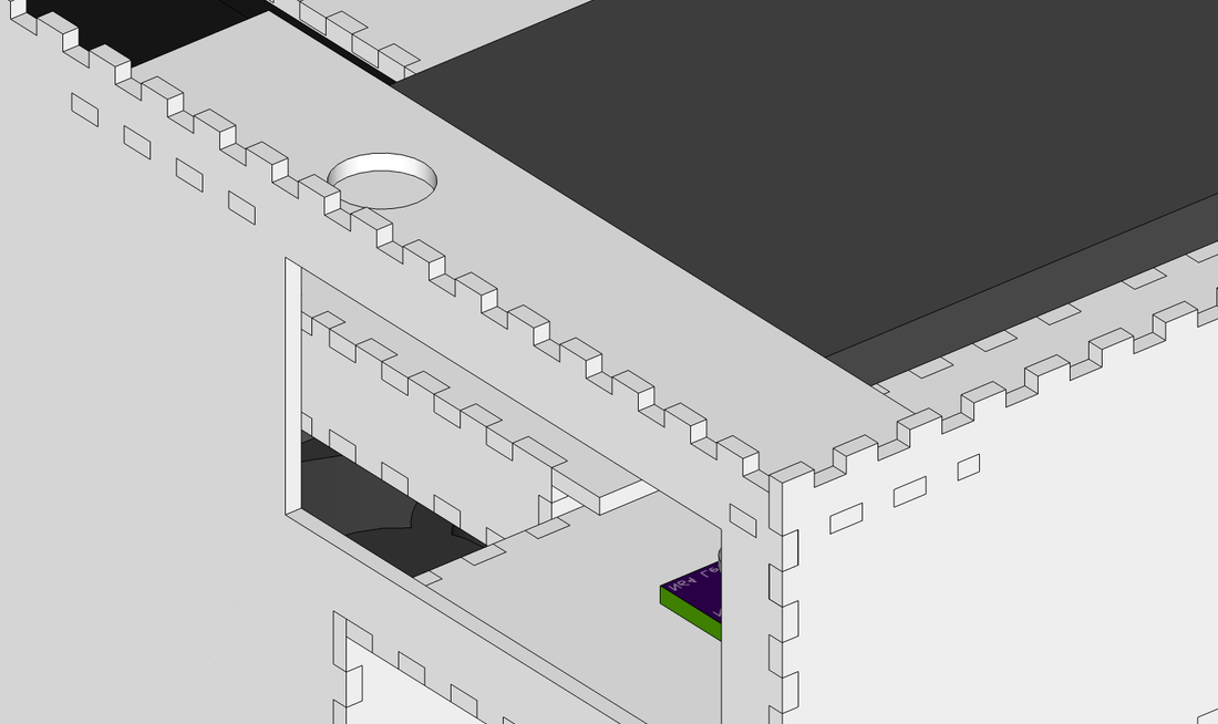
I assembled all the pieces in and did a full account of all the small changes that need to be made before the final pieces can be cut. I think after this blog post it will be time to cut some final pieces and start gluing and sanding the box,So as I integrated stuff into the box I was snipping wires and making the wiring as short as possible to reach the terminals.After a ton of soldering and cutting I ended up with pretty short wires but they extend too high above the connectors to fit in the box when I bring the cover down. You can see in some pictures that the speakers are hitting the wires and not allowing the lid to close.I measured the distance to be about 6mm to I gotta make the top part of the case higher by 6mm, not a huge deal. I also found out that I gave too much margin to the cartridge so if the game isn't buttressed it'll fall out, I'm using tape to hold it here but for the final assembly since I don't wanna redesign everything I'm just fitting in small rectangle pieces inside the cavity of the cartridge.
I assembled all the pieces in and did a full account of all the small changes that need to be made before the final pieces can be cut. I think after this blog post it will be time to cut some final pieces and start gluing and sanding the box,So as I integrated stuff into the box I was snipping wires and making the wiring as short as possible to reach the terminals.After a ton of soldering and cutting I ended up with pretty short wires but they extend too high above the connectors to fit in the box when I bring the cover down. You can see in some pictures that the speakers are hitting the wires and not allowing the lid to close.I measured the distance to be about 6mm to I gotta make the top part of the case higher by 6mm, not a huge deal. I also found out that I gave too much margin to the cartridge so if the game isn't buttressed it'll fall out, I'm using tape to hold it here but for the final assembly since I don't wanna redesign everything I'm just fitting in small rectangle pieces inside the cavity of the cartridge.
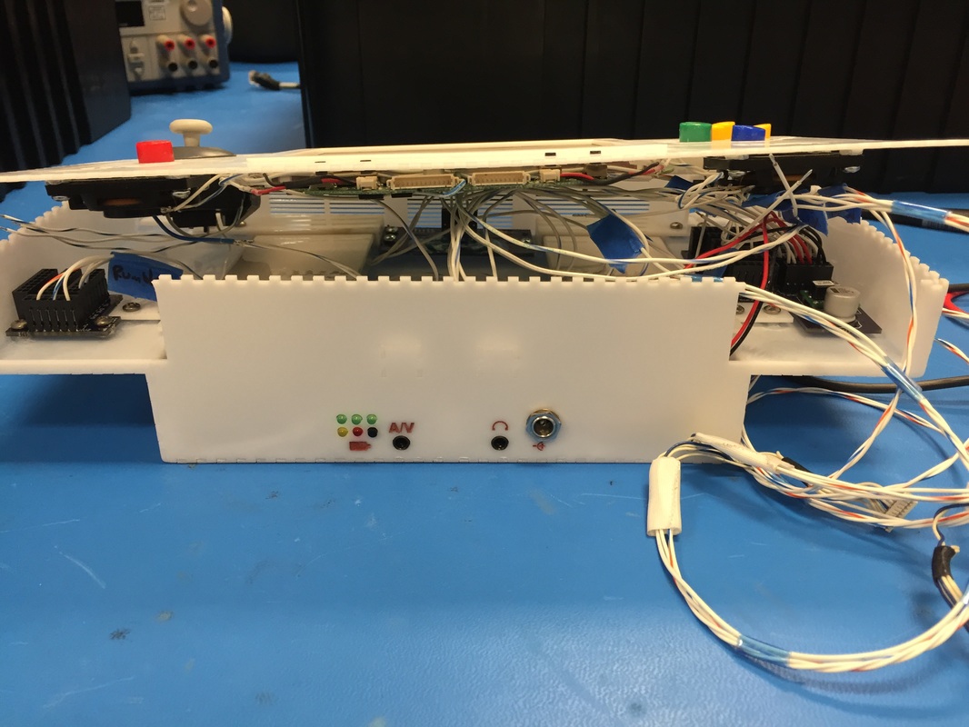
A/V Jack
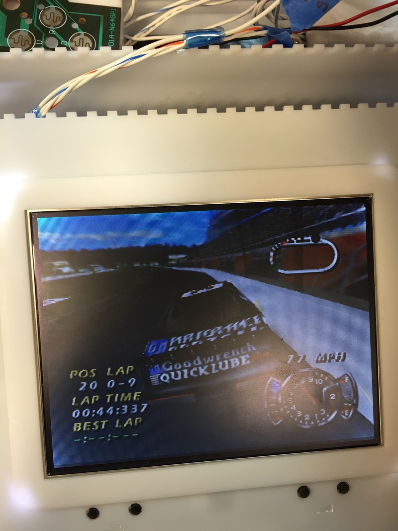
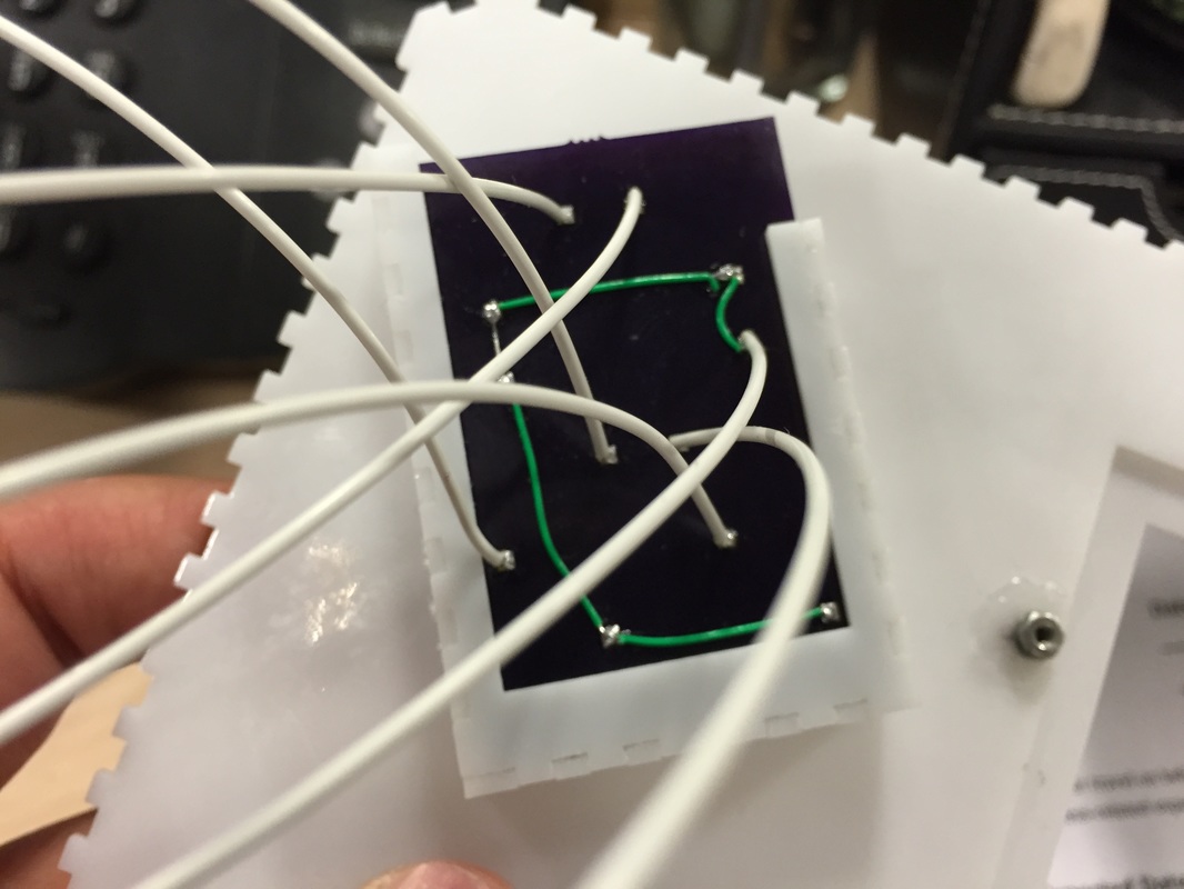
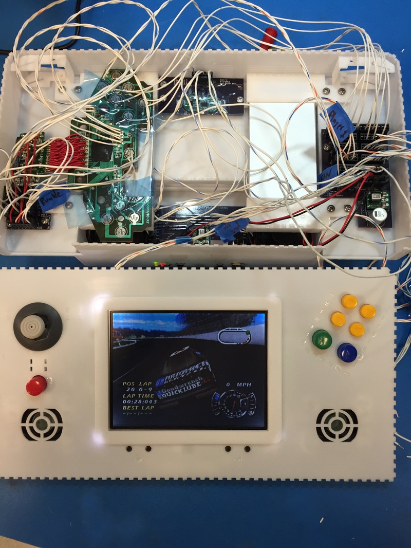
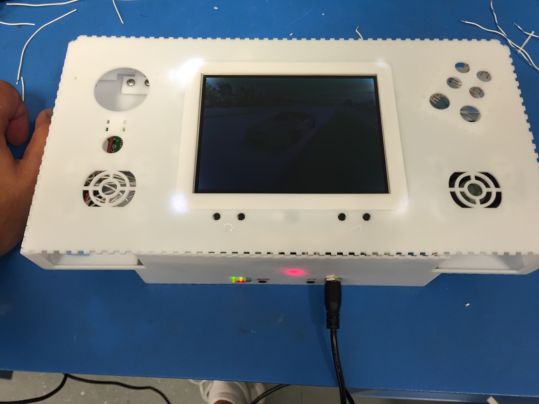
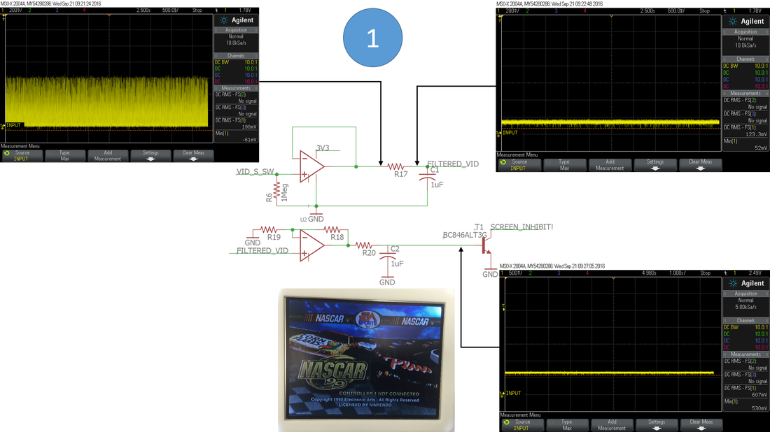
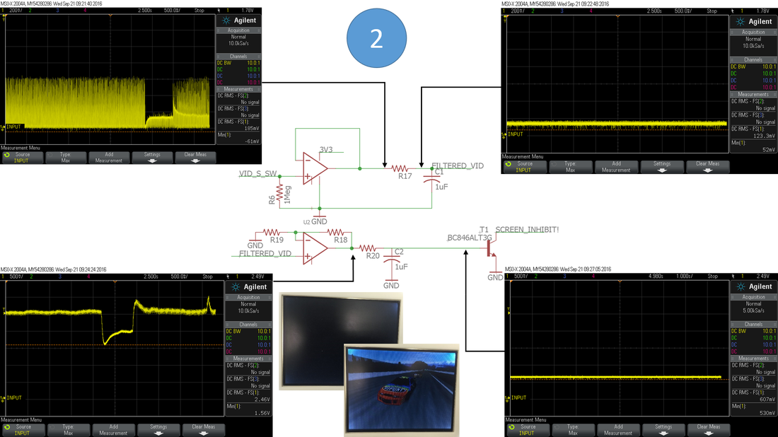
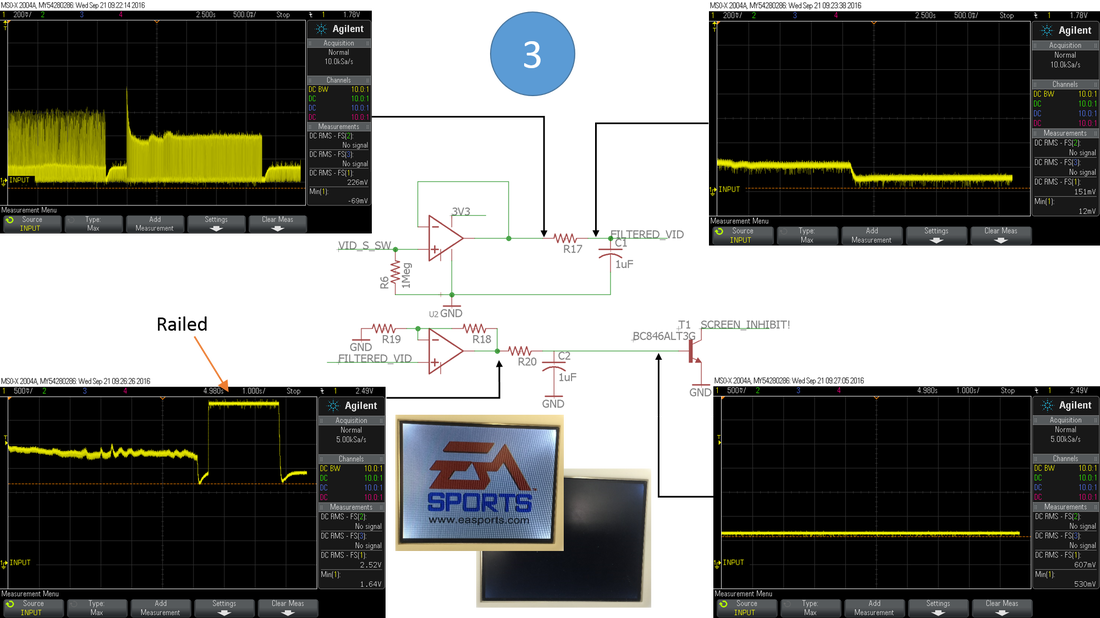
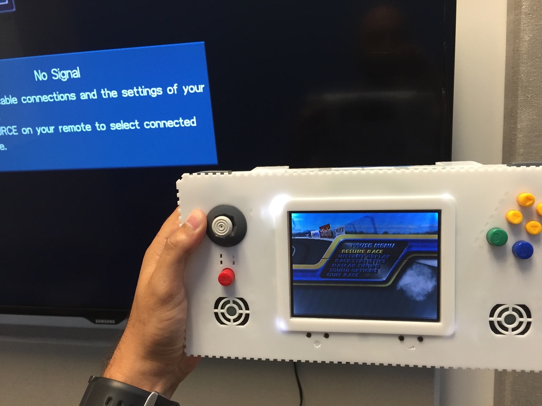
Seems like the video detection circuit isn't working too well. It still randomly cuts the screen off when the signal is too low. So I went back to the circuit and R18 from the 9k it was to 19k. Its definitely overkill to amplify the signal x20 but I'd rather overdrive the opamp the few times that the screen is fully white than to under drive it and have the screen turn off randomly. You can actually see in the diagrams below the succession of screens and how the signal looks at some parts of the circuit. Notice the dip in the incoming video signal when then screen is completely dark for a long period of time, I still need the screen to be turned. Conversely, when the screen is mostly white the opamp output rails at 3.3v for about 2.5 seconds. After the R18 switch I put it all together and tried it with a real TV and it all works!
Seems like the video detection circuit isn't working too well. It still randomly cuts the screen off when the signal is too low. So I went back to the circuit and R18 from the 9k it was to 19k. Its definitely overkill to amplify the signal x20 but I'd rather overdrive the opamp the few times that the screen is fully white than to under drive it and have the screen turn off randomly. You can actually see in the diagrams below the succession of screens and how the signal looks at some parts of the circuit. Notice the dip in the incoming video signal when then screen is completely dark for a long period of time, I still need the screen to be turned. Conversely, when the screen is mostly white the opamp output rails at 3.3v for about 2.5 seconds. After the R18 switch I put it all together and tried it with a real TV and it all works!
Controller Port Brace
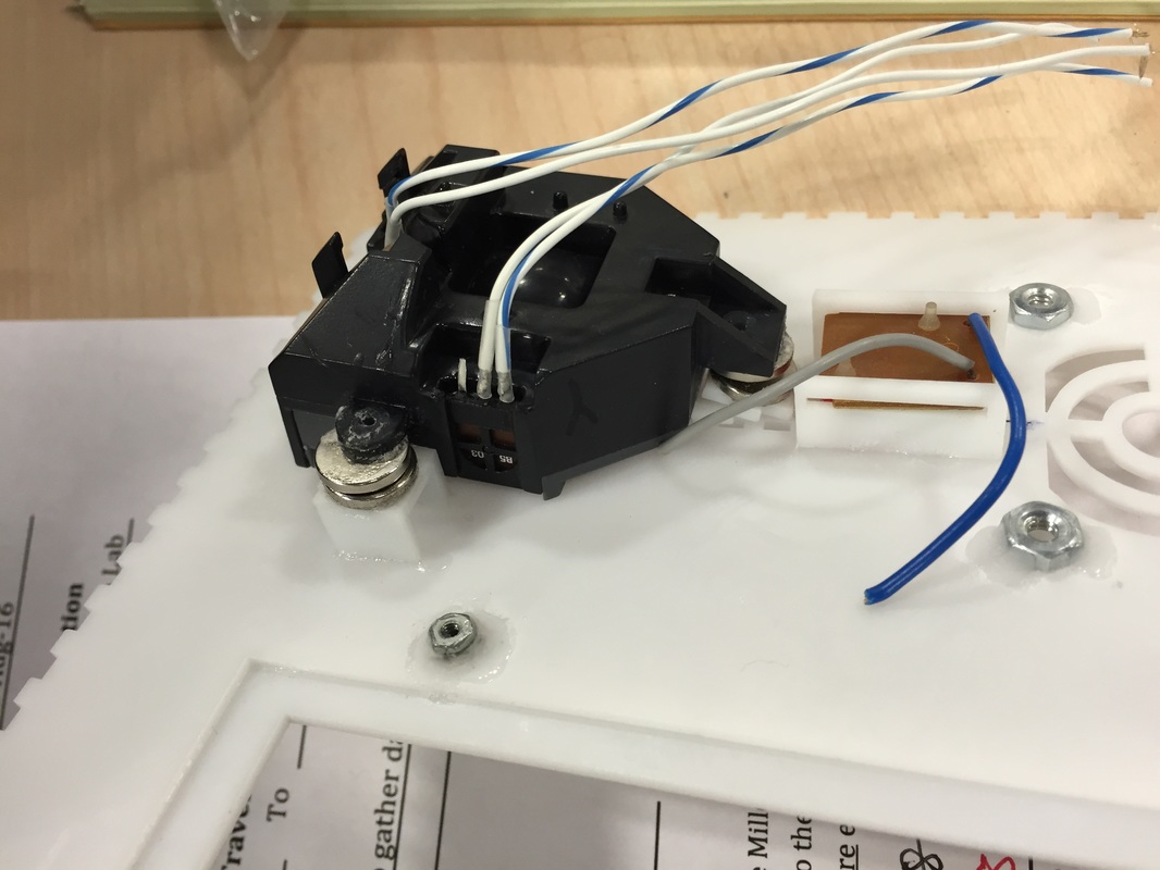
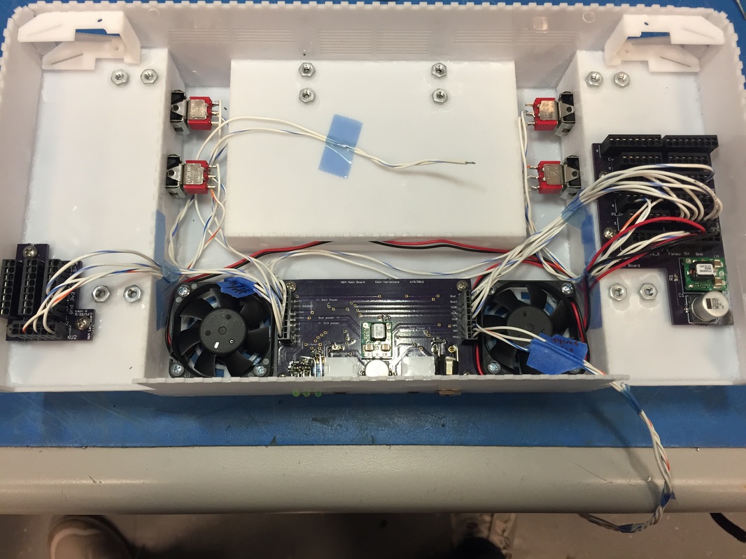
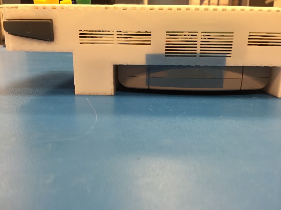
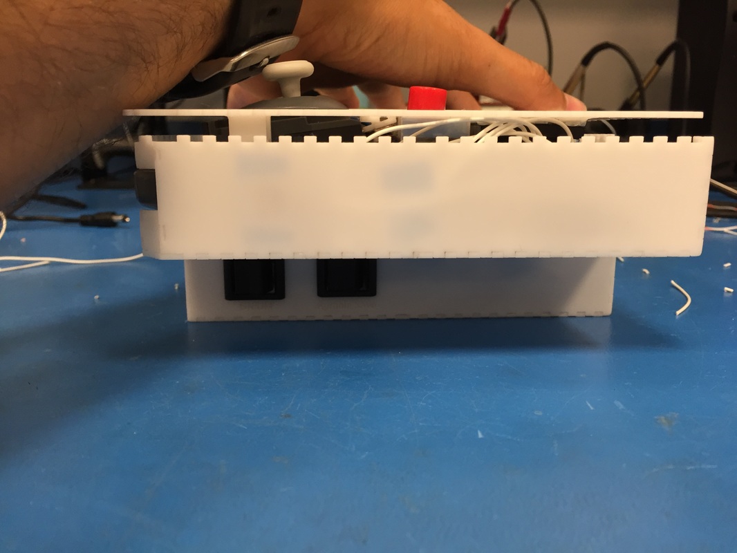
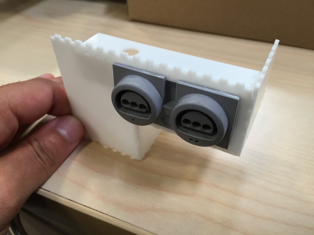
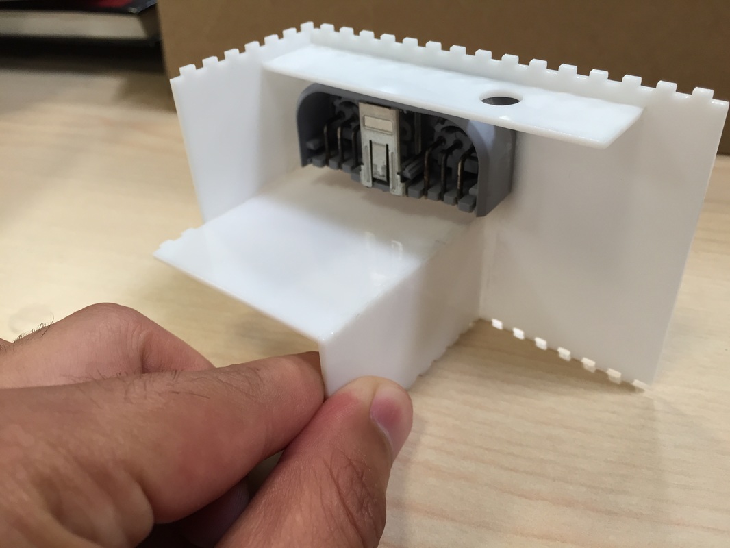
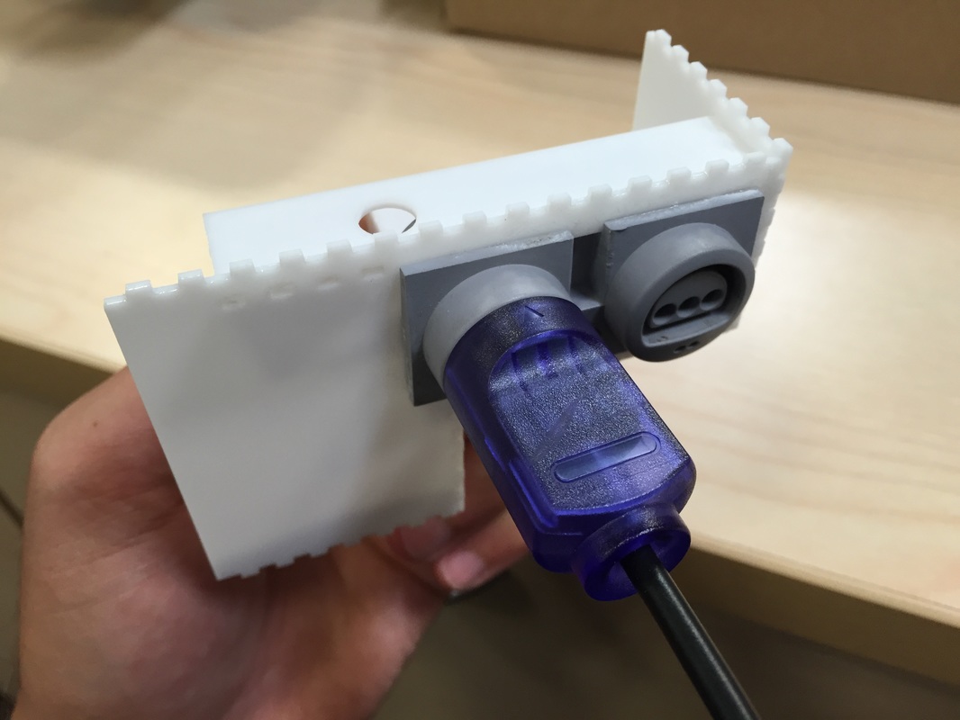
Last month I found out that the controller ports are too weak to survive repeated plug/unplug cycles of the controller plug. Although with the side of the case 6mm taller the walls would be stiffer I wasn't gonna risk it breaking so I put a brace parallel the controller port and perpendicular to the direction of plug/unplugging to stiffen that part. I cut the pieces of a small part of the case and tested it out by this time gluing the port straight onto the opening since I have spare ports after buying a new N64. Did a plug and unplug test with a controller and it all looks good. Heard some slight crackling at the joints but I bet when the whole case is there it'll hold up better. I think the design is done!
Last month I found out that the controller ports are too weak to survive repeated plug/unplug cycles of the controller plug. Although with the side of the case 6mm taller the walls would be stiffer I wasn't gonna risk it breaking so I put a brace parallel the controller port and perpendicular to the direction of plug/unplugging to stiffen that part. I cut the pieces of a small part of the case and tested it out by this time gluing the port straight onto the opening since I have spare ports after buying a new N64. Did a plug and unplug test with a controller and it all looks good. Heard some slight crackling at the joints but I bet when the whole case is there it'll hold up better. I think the design is done!
Next Step
I'm ready to cut the final pieces now! Got a lot of the kinks worked out, got lots of gluing experience, and have proven that the pieces work all together relatively well. Next post should be the final one of the assembly and integration as well as some demos of the unit. See you soon!
I'm ready to cut the final pieces now! Got a lot of the kinks worked out, got lots of gluing experience, and have proven that the pieces work all together relatively well. Next post should be the final one of the assembly and integration as well as some demos of the unit. See you soon!