Start Button
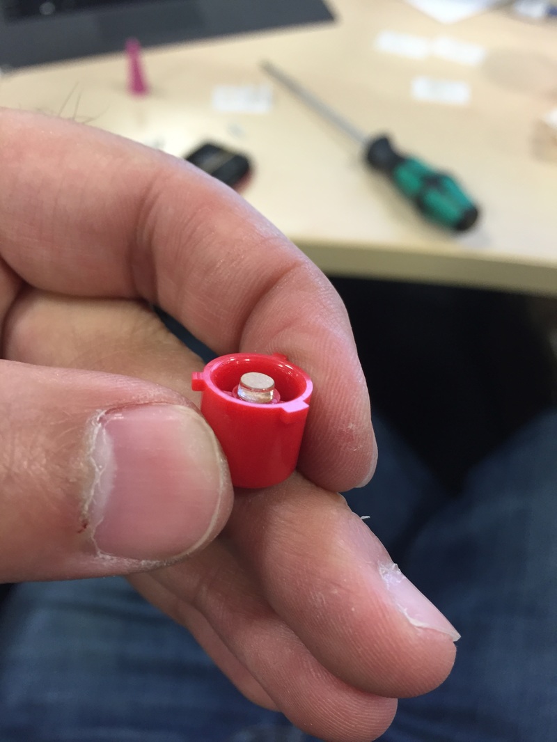
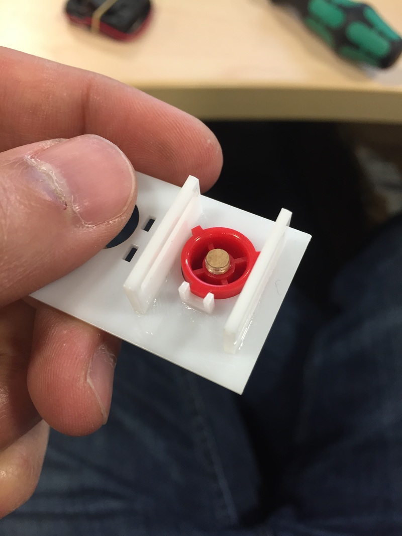
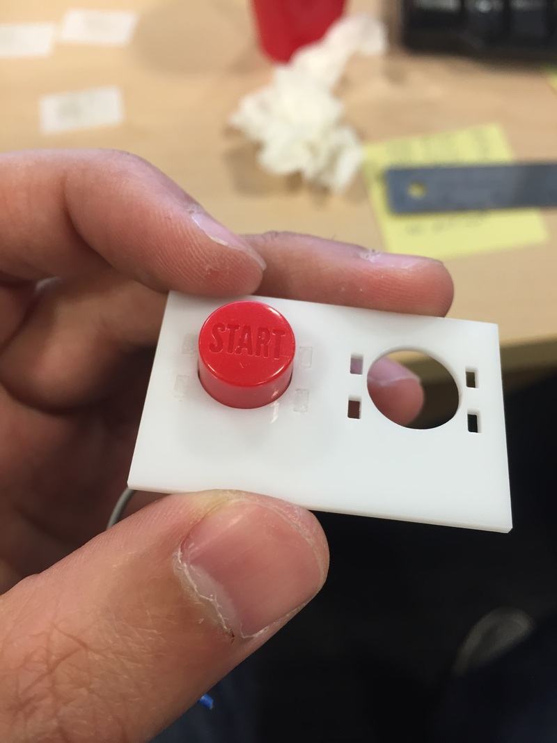
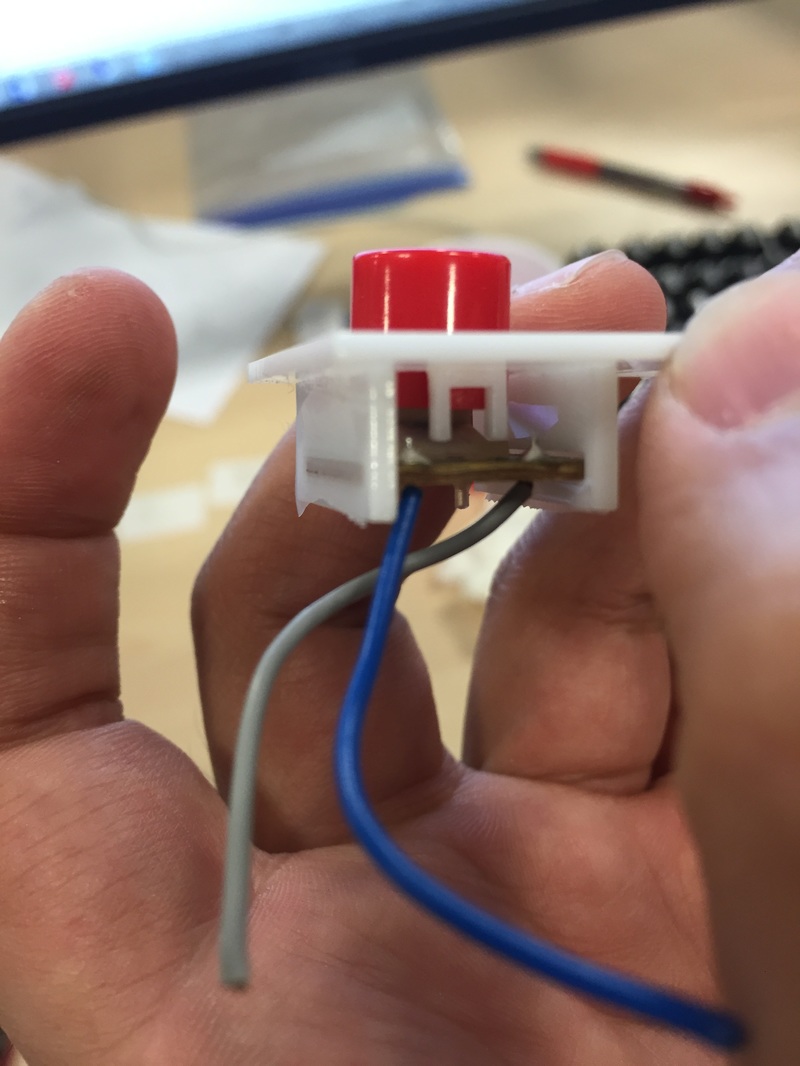
Started out with building a tiny bracket for the Start button. It's similar to the shoulder buttons in the way the bracket holds the PCB in its slots. Had to add a tiny piece under the Button to make it be able to actually actuate the membrane underneath since the button wasn't meant for the PCB. All in all it's a nice and simple design.
Started out with building a tiny bracket for the Start button. It's similar to the shoulder buttons in the way the bracket holds the PCB in its slots. Had to add a tiny piece under the Button to make it be able to actually actuate the membrane underneath since the button wasn't meant for the PCB. All in all it's a nice and simple design.
N64 Logo
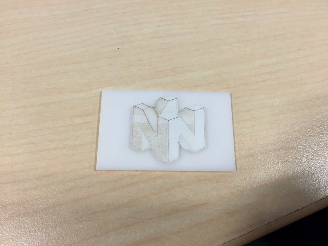
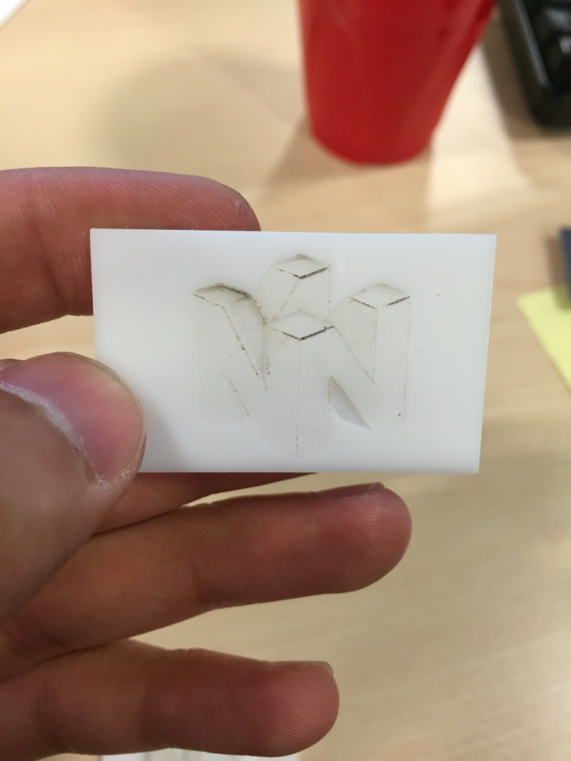
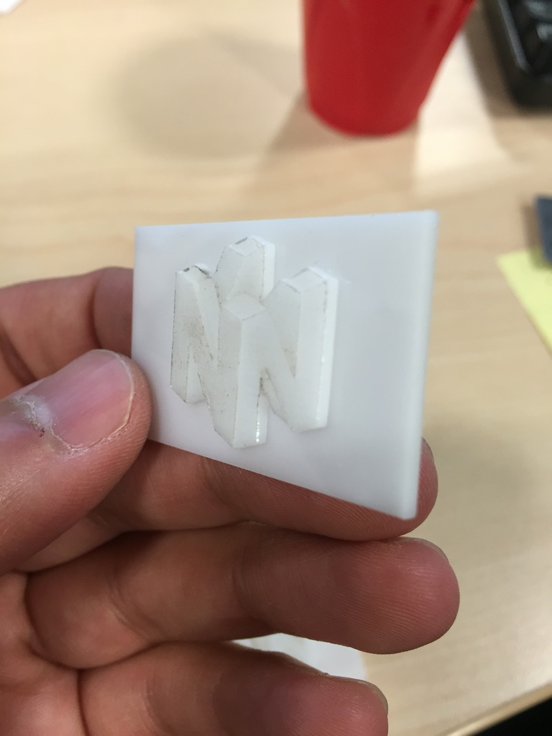
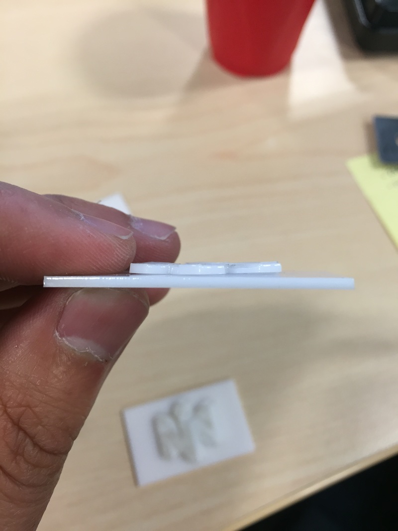
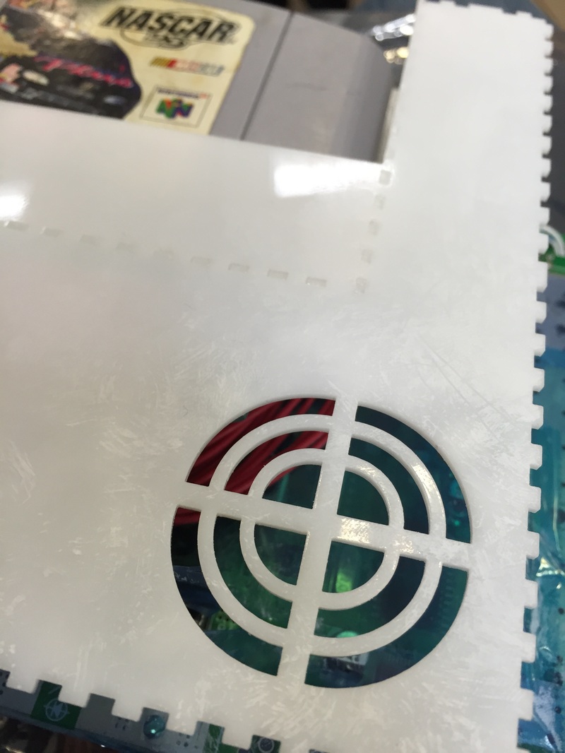
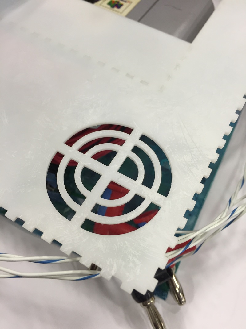
Got a bit creative and wondered if I could engrave the N64 logo into acrylic with different power levels for each color (since the logo only has 4 colors). The results are neat but I wouldn't put it on the box quite yet. When I cut the logo outline out you can see a bit of warping from the engraving process, and in general the different power levels have a distinct depth to them but I can't really make the different sections pop which is frustrating. The only shading you see on there now is because the cover paper melted on to the acrylic. Will have to experiment, not even sure where to place it on the case.
Got a bit creative and wondered if I could engrave the N64 logo into acrylic with different power levels for each color (since the logo only has 4 colors). The results are neat but I wouldn't put it on the box quite yet. When I cut the logo outline out you can see a bit of warping from the engraving process, and in general the different power levels have a distinct depth to them but I can't really make the different sections pop which is frustrating. The only shading you see on there now is because the cover paper melted on to the acrylic. Will have to experiment, not even sure where to place it on the case.
Case Bottom
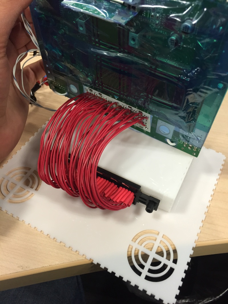
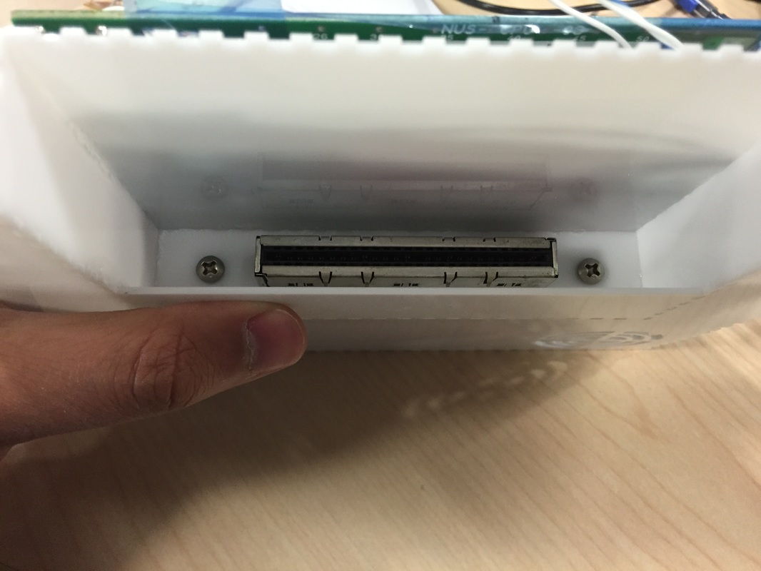
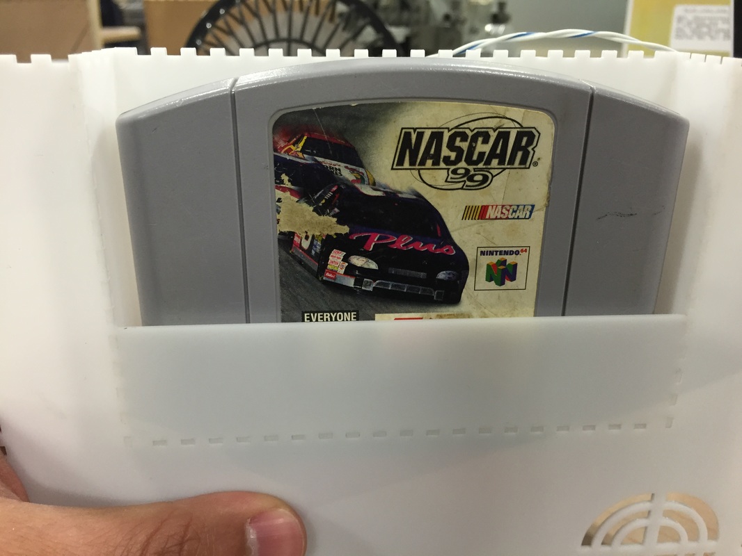
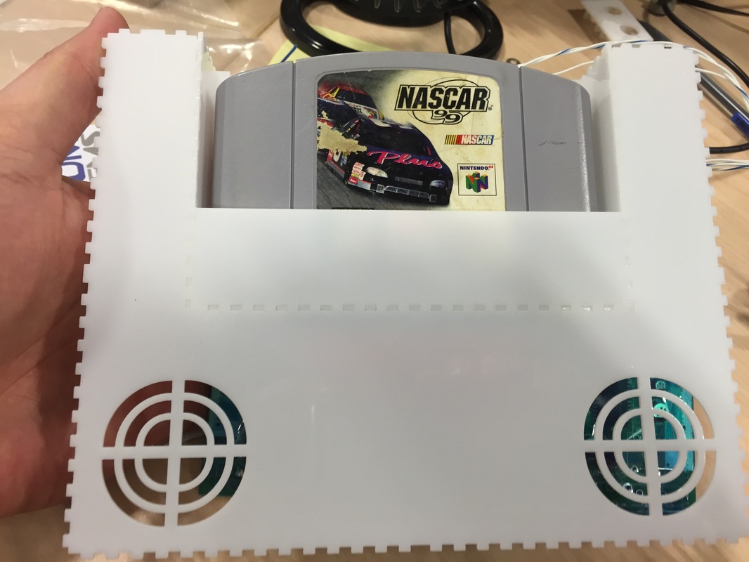
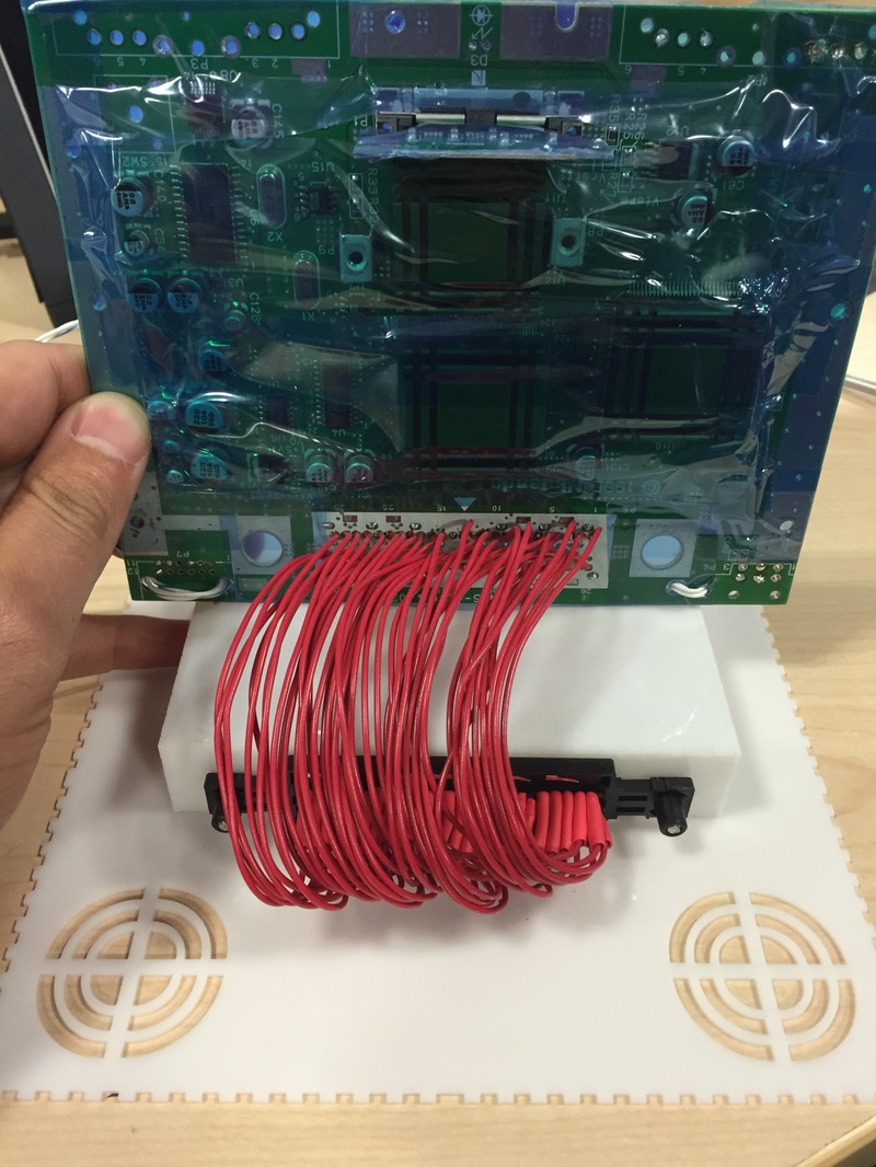
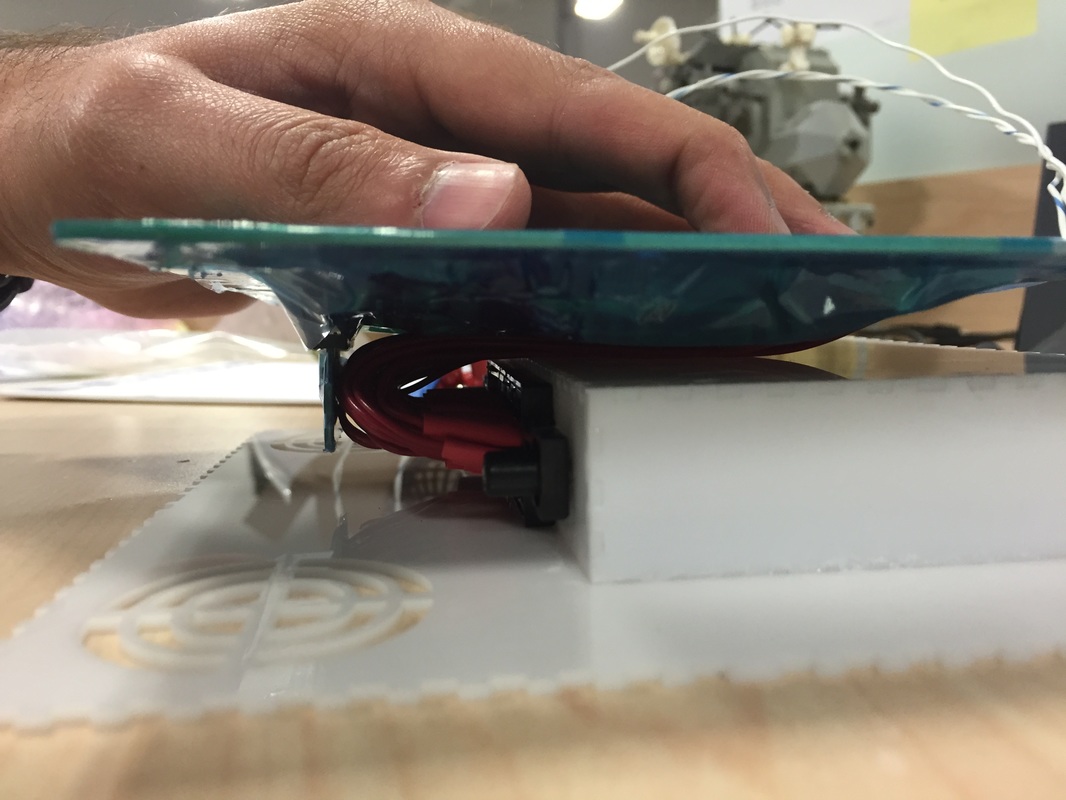
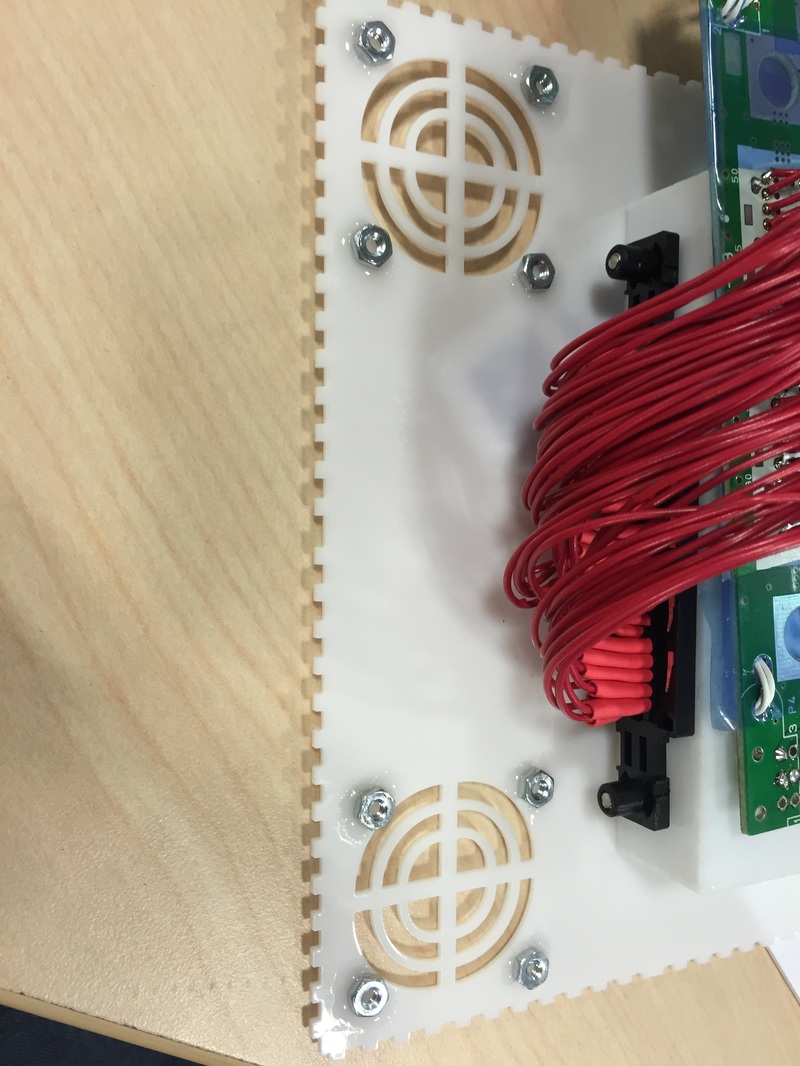
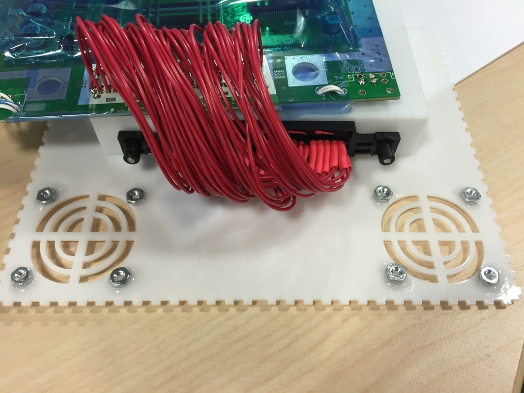
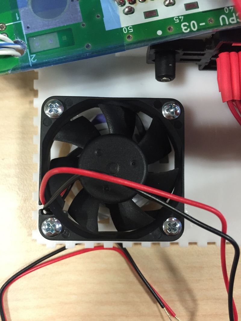
Cut the bottom part of the case that holds the game cartridge and glued it. This piece also has the holes for the two fans so I glued some nuts down for those (aligning those holes was pretty challenging).The whole thing came out really nice, The screws held everything really well and the gluing job was nice and clean. Used 4-40 screws and nuts to hold stuff down.
Cut the bottom part of the case that holds the game cartridge and glued it. This piece also has the holes for the two fans so I glued some nuts down for those (aligning those holes was pretty challenging).The whole thing came out really nice, The screws held everything really well and the gluing job was nice and clean. Used 4-40 screws and nuts to hold stuff down.
Superglue needs to vent as it cures. The vapors will cloud up anything they settle on. I was an idiot and left the whole thing inside a bag overnight as the glue cured and came back to a messed up case.... will have to redo this bit.
Audio/Video Jack
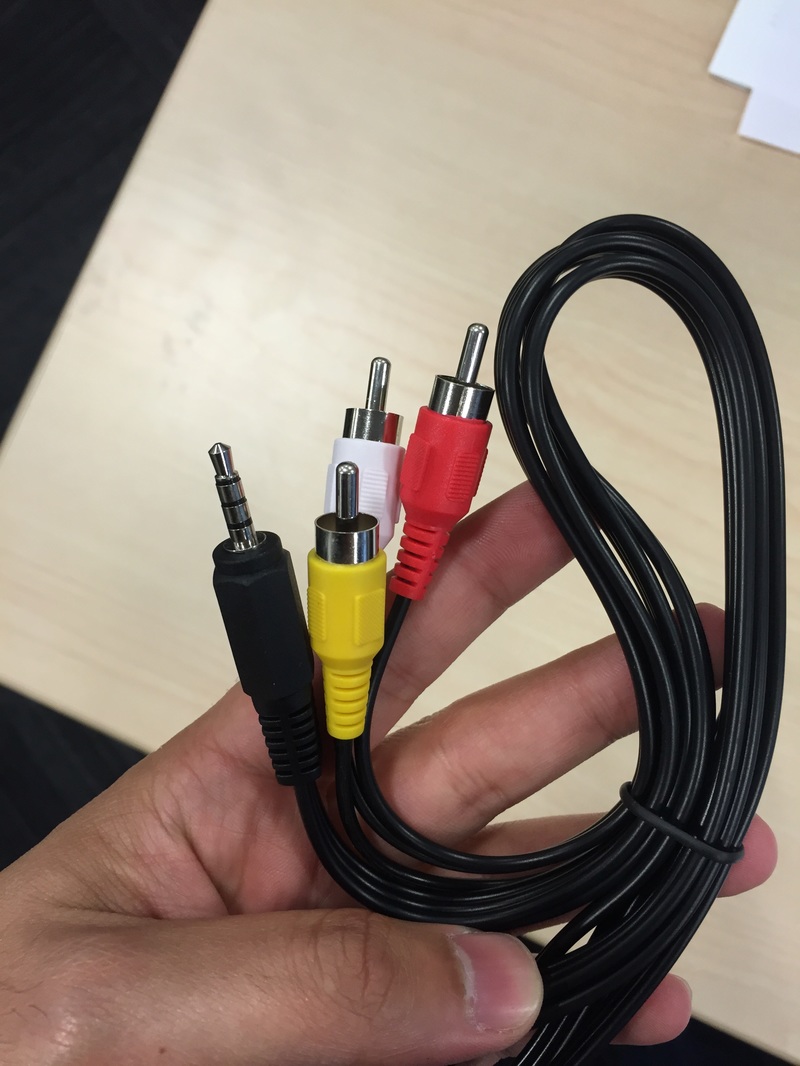
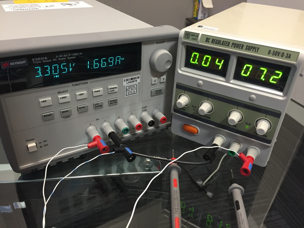
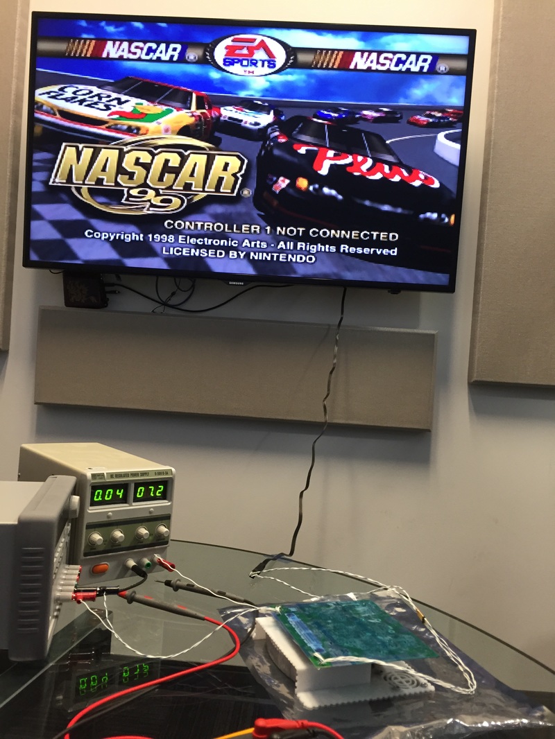
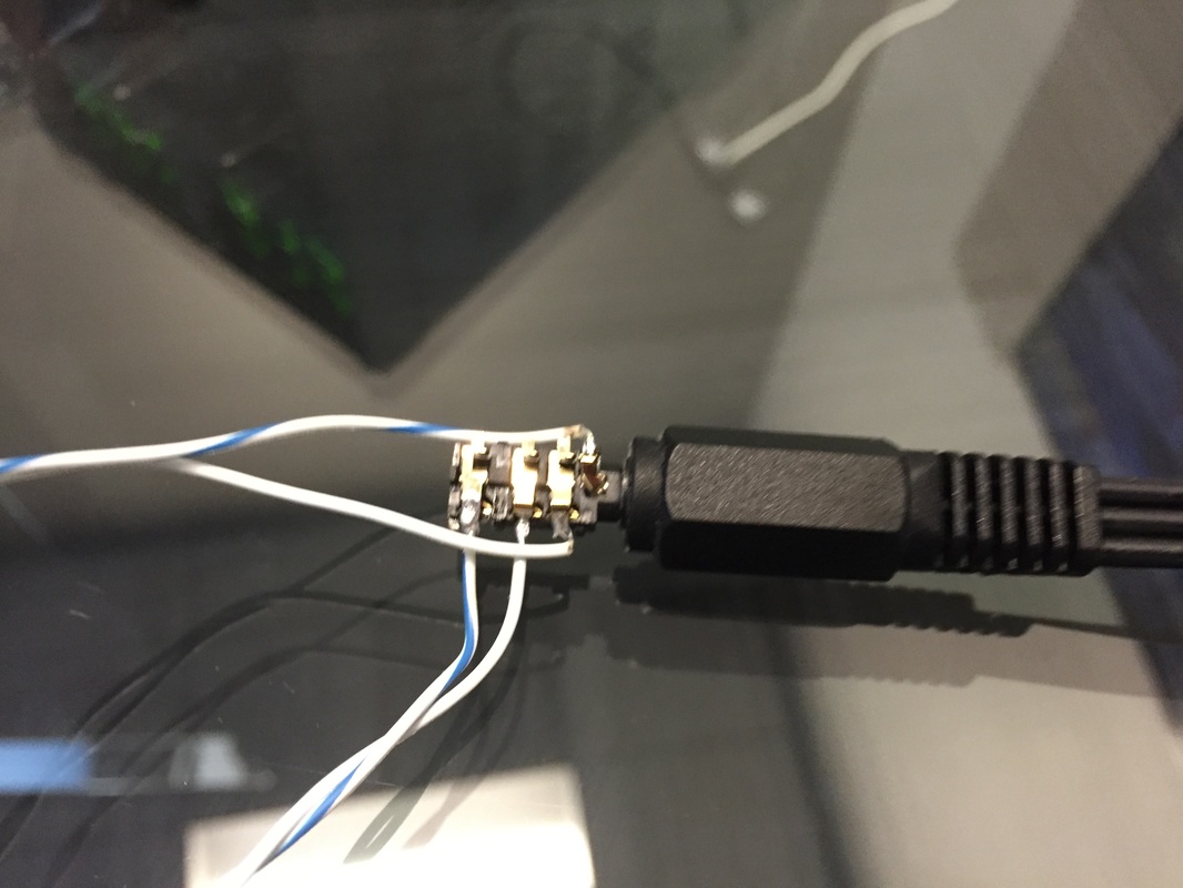
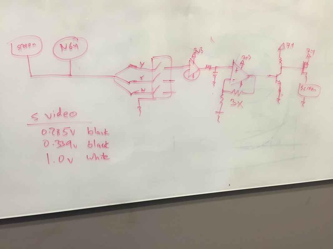
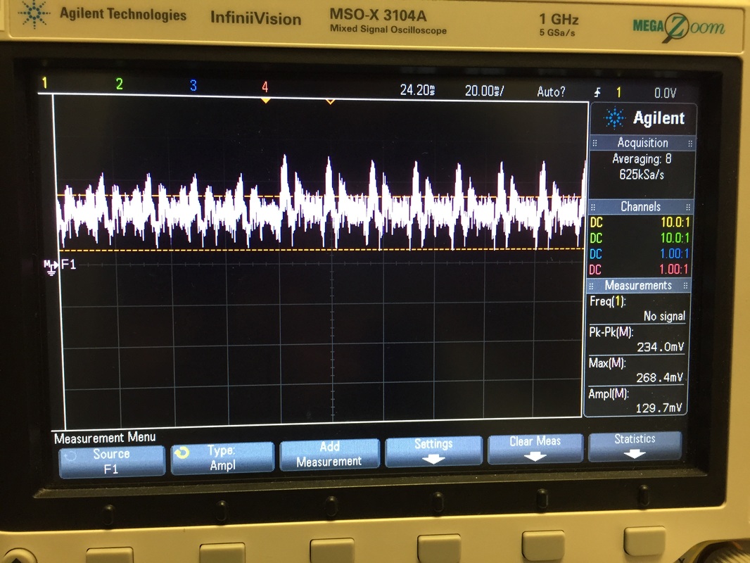
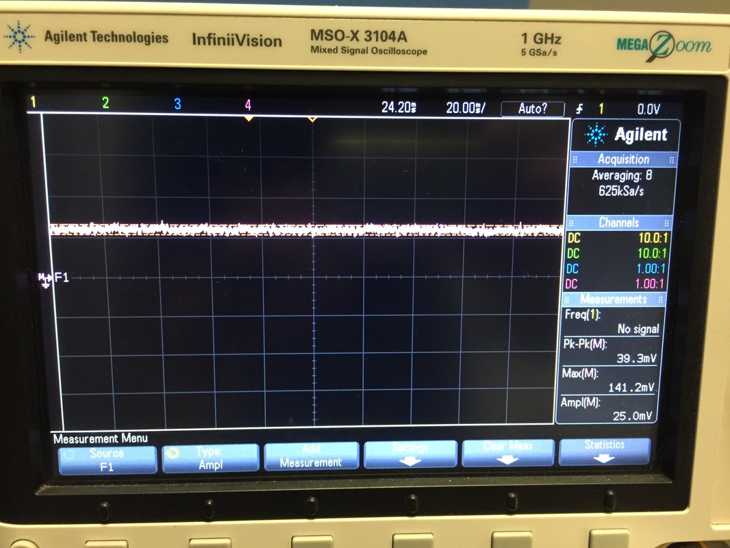
Hooked the Component cable thru an RCA cable I bought which takes the yellow/red/white component inputs to a 3.5mm headphone jack with 4 conductors (4th conductor is ground). From here I wired it to the S video and audio coming from the N64 that would normally go to the screen and took it to the audio jack. Magically, it worked without blowing up the unit or the TV! very excited. After a little research I coworker found that the S-video signal goes to a minimum of 0.285v so if I can amplify that signal I can tap it off the switched side of the connector (remember the barrel connector I'm using has switched contacts on the tip and 2 rings which are NC but become open when a jack is inserted in). So when I don't have something plugged in the Svideo signal will flow through the switched side and get amplified so that I can use the video signal itself as a way to turn on the screen. If I insert the jack in then the switch becomes open and the amplifier reads zero which means it shuts off the screen.Will have to SPICE and try out the circuit of course but its got a good chance of working. I took some scope plots and you can see the signal when its active vs when there is no cartridge plugged in. So there's always some voltage on that line. I think I'll have to tie it lightly high or low to get the desired effect when the jack switch is disconnected. You can also see that the 7.2V supply draws barely any current with no screen present since this supply is mostly used for the screen.
Hooked the Component cable thru an RCA cable I bought which takes the yellow/red/white component inputs to a 3.5mm headphone jack with 4 conductors (4th conductor is ground). From here I wired it to the S video and audio coming from the N64 that would normally go to the screen and took it to the audio jack. Magically, it worked without blowing up the unit or the TV! very excited. After a little research I coworker found that the S-video signal goes to a minimum of 0.285v so if I can amplify that signal I can tap it off the switched side of the connector (remember the barrel connector I'm using has switched contacts on the tip and 2 rings which are NC but become open when a jack is inserted in). So when I don't have something plugged in the Svideo signal will flow through the switched side and get amplified so that I can use the video signal itself as a way to turn on the screen. If I insert the jack in then the switch becomes open and the amplifier reads zero which means it shuts off the screen.Will have to SPICE and try out the circuit of course but its got a good chance of working. I took some scope plots and you can see the signal when its active vs when there is no cartridge plugged in. So there's always some voltage on that line. I think I'll have to tie it lightly high or low to get the desired effect when the jack switch is disconnected. You can also see that the 7.2V supply draws barely any current with no screen present since this supply is mostly used for the screen.
Next Steps:
I updated the block diagram and started working on PCB's and connector placements. I'm not going to have anything soldered to each other so I'll be using terminal blocks with push action release pins to hold harnessing. Gotta start doing PCB stuff and get that sent out to be made. Just found out that EAGLE which is a free schematic and layout software is limited to 2 layers and 80x100 mm boards. Kinda crappy but I think it'll be enough now that I've broken up my boards a bunch. Once the boards are ordered I can buy components from Digikey which will help nail some more things down. In the mean time I'm pretty much done with the model which means I can start cutting pieces and gluing (again...)
I updated the block diagram and started working on PCB's and connector placements. I'm not going to have anything soldered to each other so I'll be using terminal blocks with push action release pins to hold harnessing. Gotta start doing PCB stuff and get that sent out to be made. Just found out that EAGLE which is a free schematic and layout software is limited to 2 layers and 80x100 mm boards. Kinda crappy but I think it'll be enough now that I've broken up my boards a bunch. Once the boards are ordered I can buy components from Digikey which will help nail some more things down. In the mean time I'm pretty much done with the model which means I can start cutting pieces and gluing (again...)
|
| ||||
