Batteries
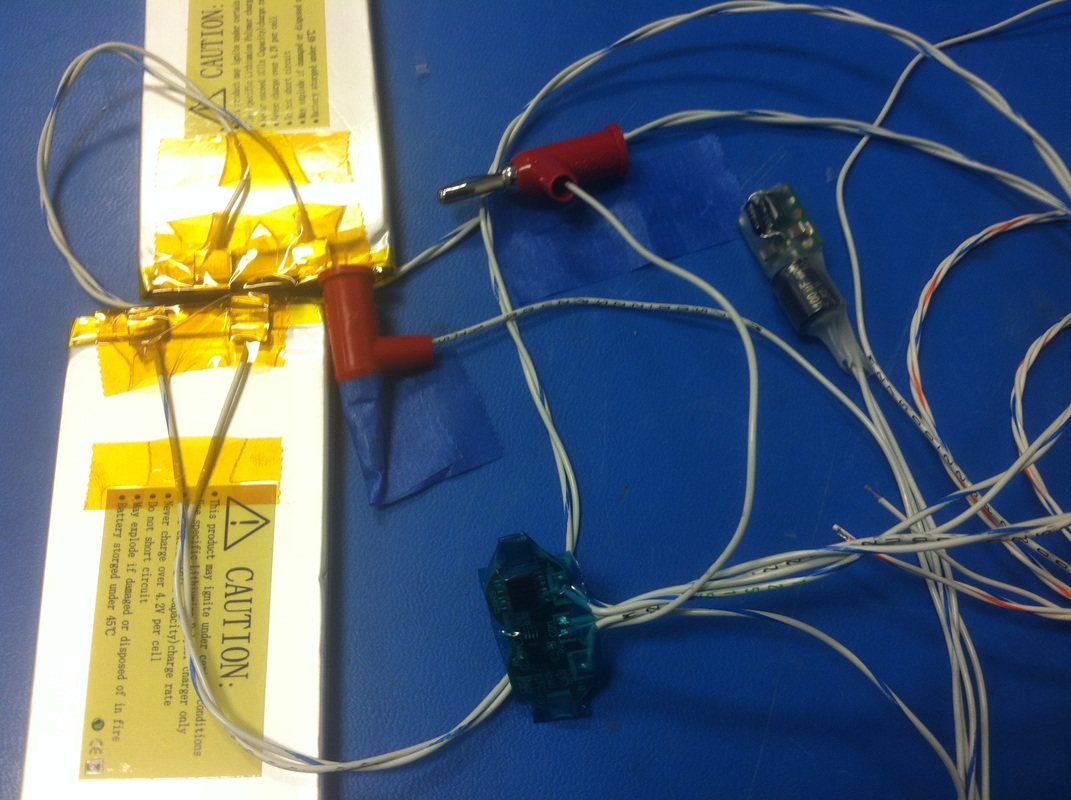
Got my replacement battery protection board in the mail. It seemed to not work at first but after a while it showed 7.4V on the output. I'm guessing it had to fill up some capacitors or something. Either way I got it wired up the way the diagram in the package said and put shrink tubing around the board for protection. Then I wired it to the main board along with the 3.3V regulator, which is a Texas Instruments module (PTH08080WAH) that takes in the 7.4V from batteries and turns it to a settable voltage (set to 3.3V by a 2K resistor).
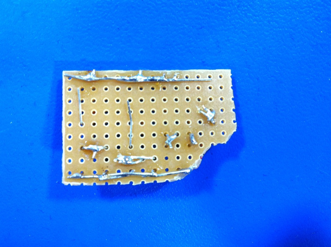
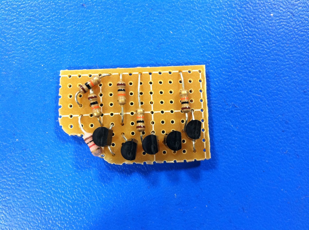
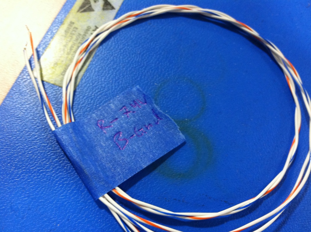
I also wired up a low voltage detector found here. Where the two wires stick out on the back view is where the red and green LED's attach once I thread them through the case.
I also wired up a low voltage detector found here. Where the two wires stick out on the back view is where the red and green LED's attach once I thread them through the case.
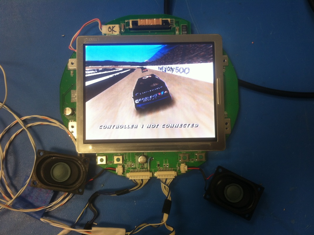
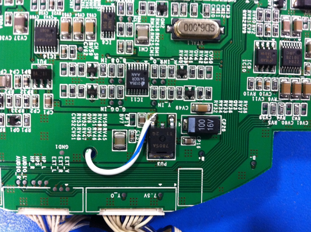
Screen
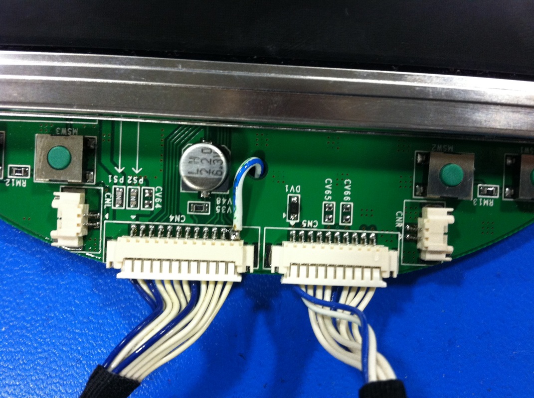
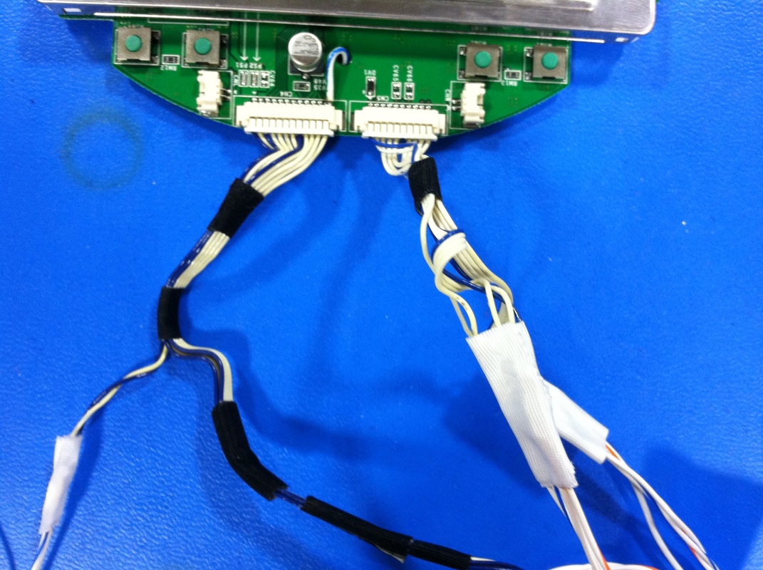
Wired the screen according to the general schematic I had posted in a previous post. Took advantage of the cables that came with the PSone screen. Also wired the output of the 5V regulator to pin 12 of one of the headers which turns the screen on. I'm using bacman's pinnout and keeping the composite video and audio, headphones, and power. The headphone switch turns out is internally pulled high. If you want the speakers to work you'll have to ground that wire. I'm gonna eventually put it on a switch or something.
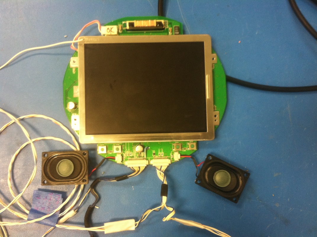
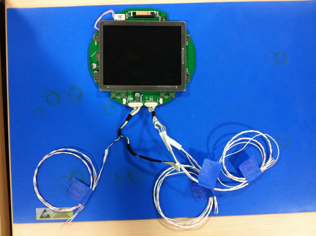
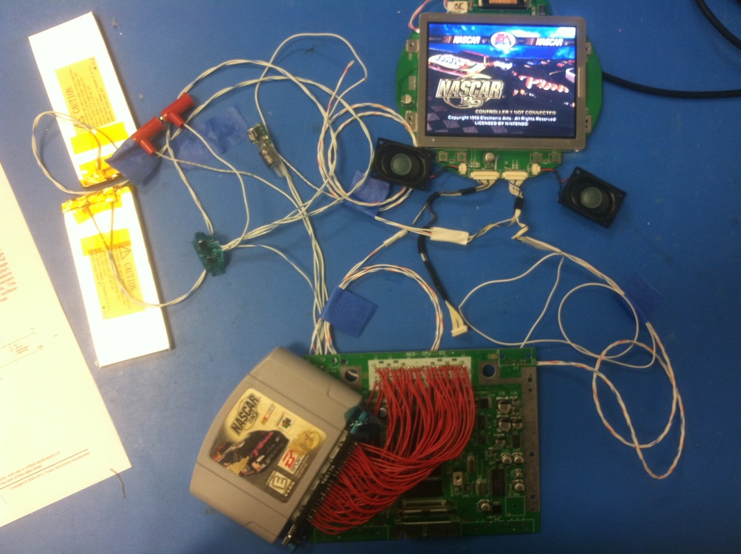
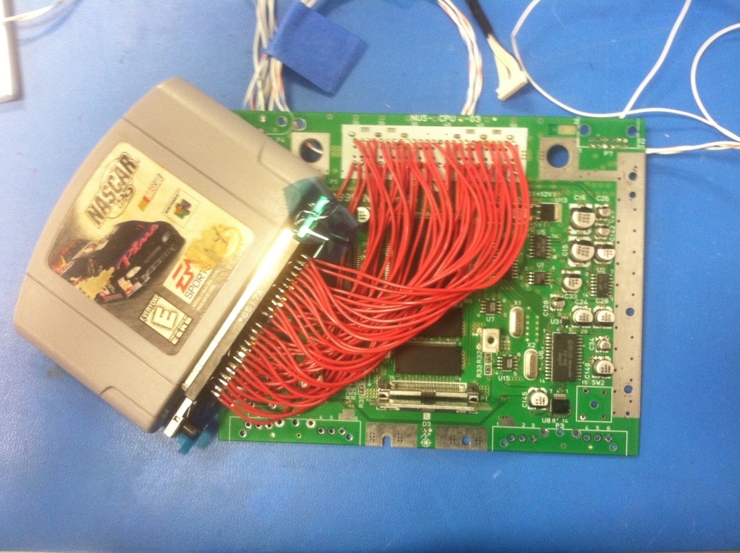
Putting it Together
Wired everything up and it works! got music out of the speakers too. Really excited about the progress. Next up will probably be case modding.