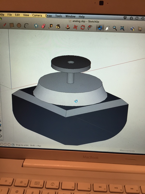
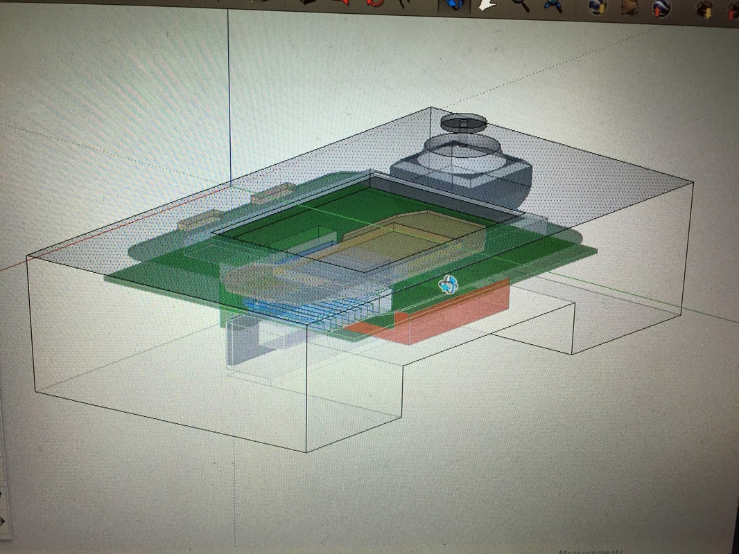
Had put this project on hold for a while. I think the mechanical aspects of the console really intimidated me. So with the help of my girlfriend (architect!) i'm moving forward with the project and enlisting her help in designing the case. We will laser cut it out of 60 mil white acrylic and assemble with glue and notching. Still working on the in's and outs...
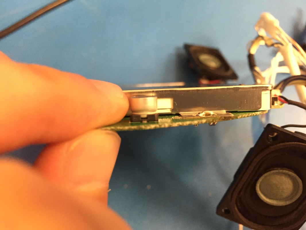
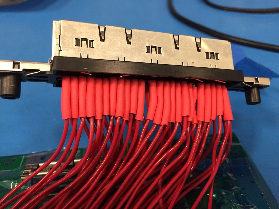
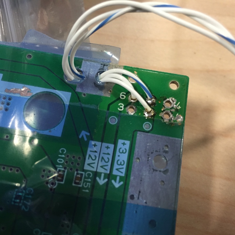
While she focuses on the case design I dusted off the electrical components. My soldering job wasn't very good and many connections had broken. So cleaned up a bit, put heat shrinks on the cartridge connections and added banana plugs to everything for ease of prototyping on the bench. I'll be soldering connections when the systems in the case since banana plugs won't fit in the there. I also made sure to include strain reliefs wherever I could. Lastly I secured the screen to its driver board through some bus wire. The aluminum shielding wouldn't directly solder to the PCB pads for some reason.
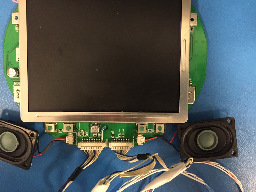
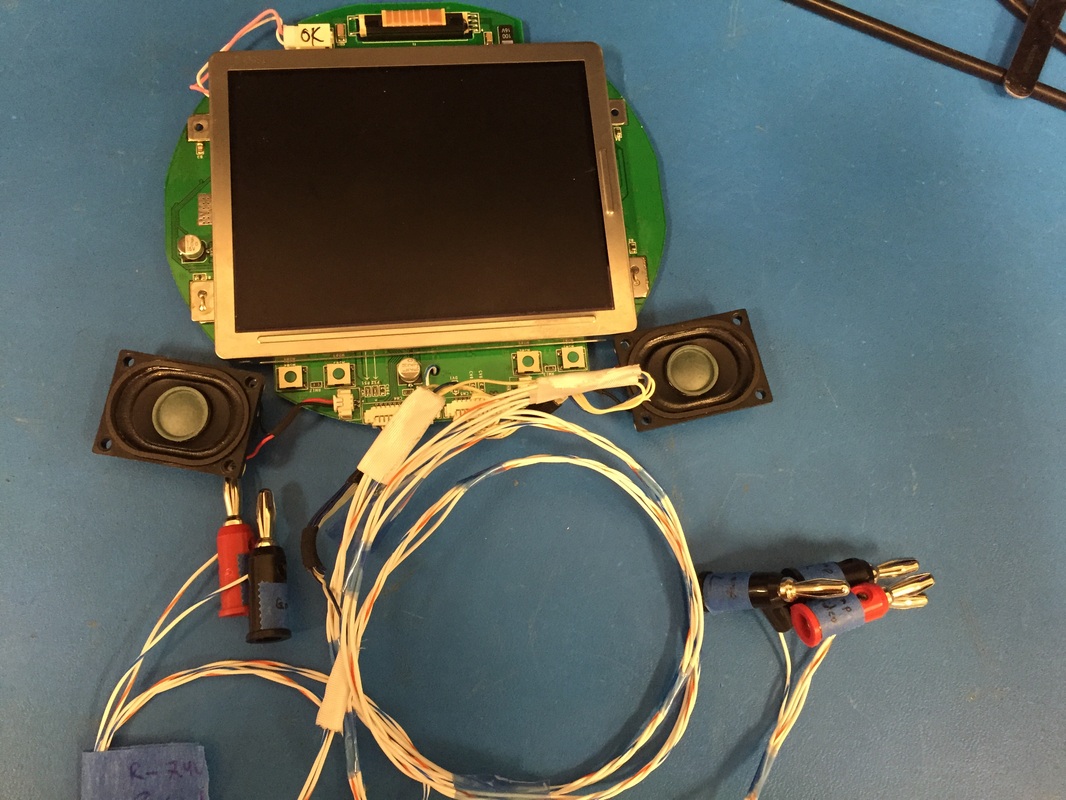
Powered up the system and It all works great!
One thing I found was that the 5V sense line on the screen doesn't seem to be doing anything. All the guides online say that you should tie that line to the 5V regulator on the back of the board to turn on the module but when I disconnected the module still worked. Even grounded it and it stayed on. Gonna leave it connected but will have to disable the screen by pulling power to it. Need a power transistor since the screen pulls 0.5-1A so will look for a thru hole version of that for testing.
Also gonna need a tiny fan in there...we'll see if there is room inside.
Lastly, decided to build my own button pad pcb to detect the A, B, and C buttons using the original control's components. This thread has some good insight into layout out your own button pad pcb. Insights like "you're PCB needs to be ENIG treated so the pads don't tarnish". Lucky for me OSHPark already ENIG treats all its boards for free.
Next steps:
-Exact dimensions for anything protruding from the case so that laser cutter can do its job correctly
-Polish the schematics/block diagram with part numbers
-Order parts
-Design and order button pcb
-Test everything on the bench
Exciting times!
