Rumble Pak
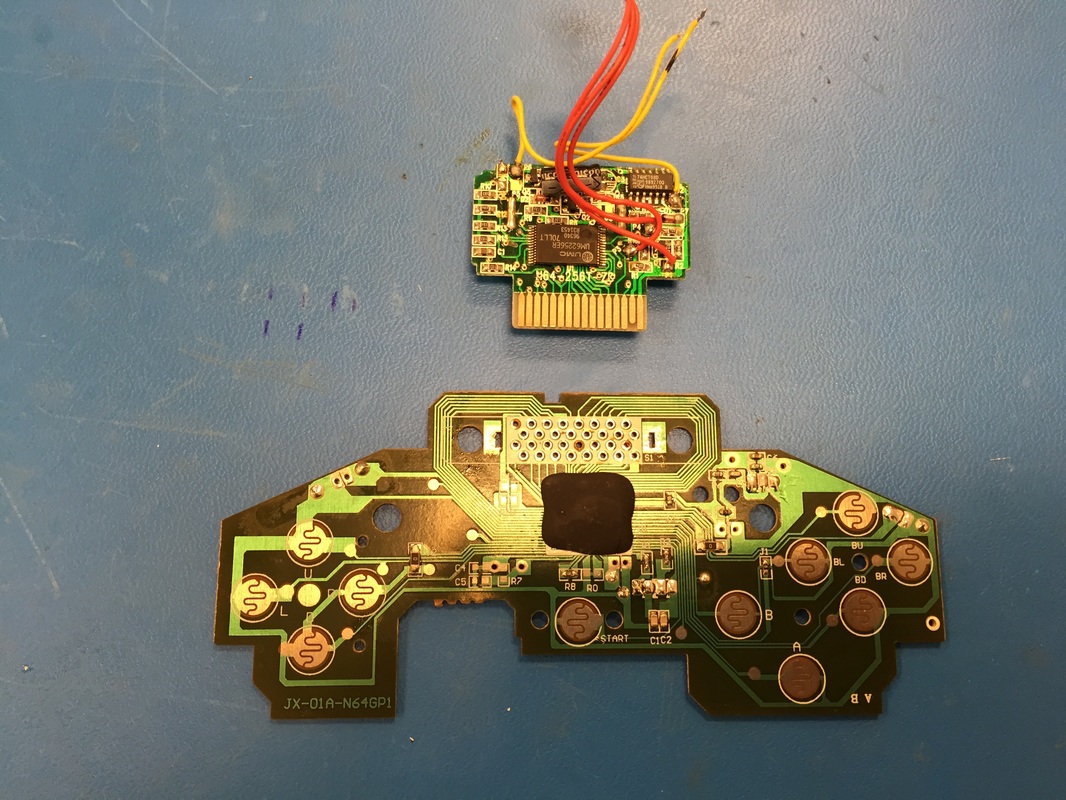
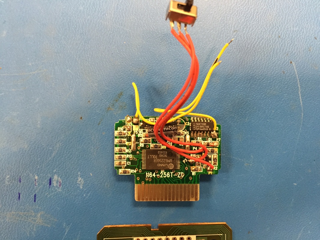
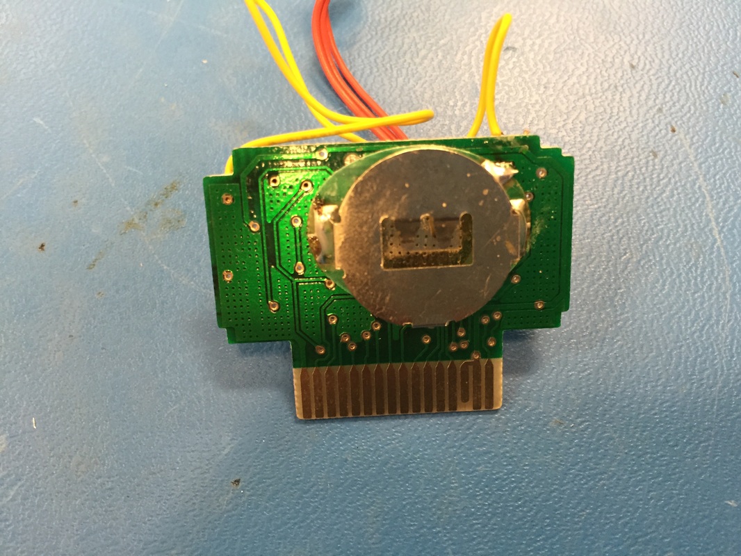
Had time to try out the motors today. I had 3 different vibration motors from different places. Ran them at 3.3V and they seemed fine even though they are probably rated only for 5V. I'll probably look into buying two identical ones from Digikey or something. The Rumblepak circuit board seems like the motor is connected to its batteries by a simple high side mosfet. The coin cell battery keeping the memory alive was dead so I'll have to replace that. But otherwise I'm gonna hook up two motors in parallel and hope that this circuit board can handle it. The motor that came with it drew about 100mA so maybe I'll find two and 50mA. The motor will connect to the 3.3V regulator where the two AA batteries would usual plug in.
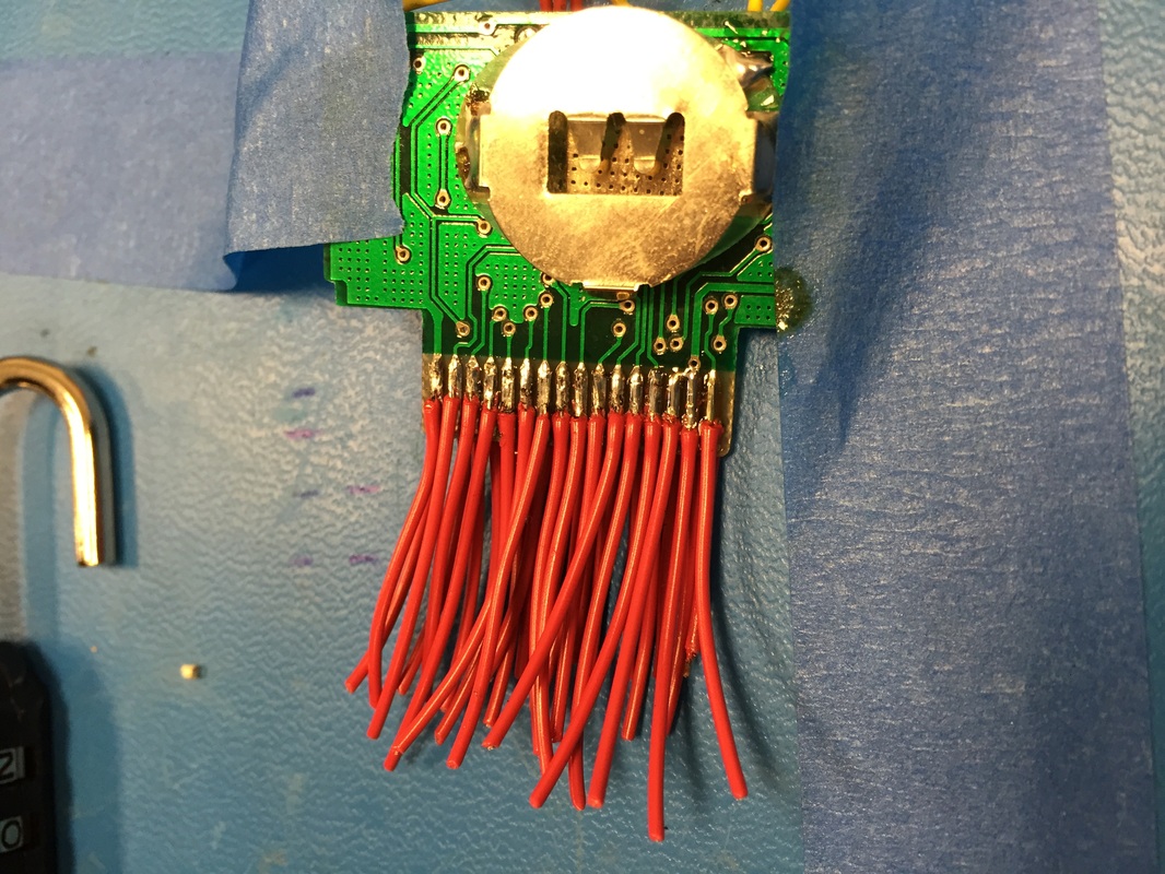
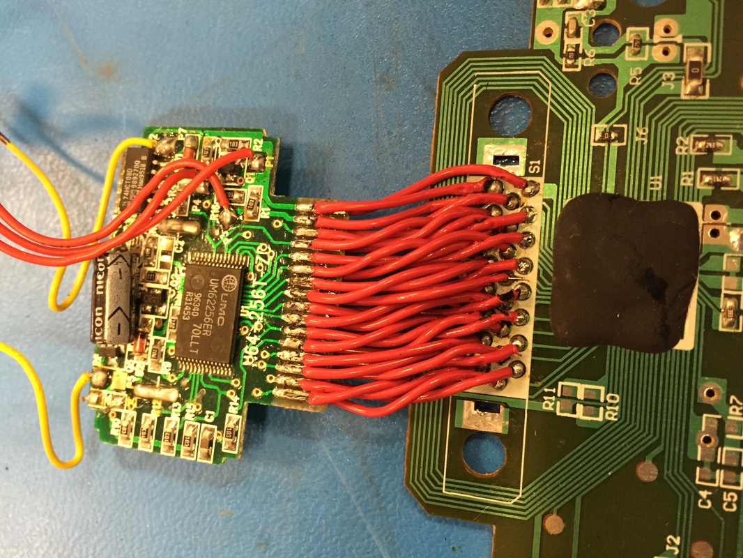
I moved ahead and soldered the rumblepak to the controller board. Lots of tiny wires with lots of places to mess up. Got pretty lucky and had no incorrect connections or shorts. One of the pads was completely torn from when I desoldered the connector so had to do some root canal and solder to the trace. Used the hole as strain relief. Wires are the same ones from the cartridge relocation job.
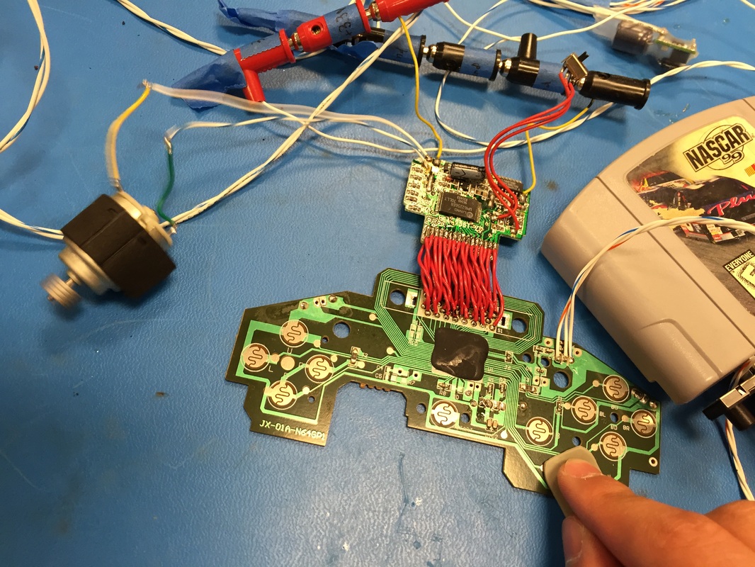
In the last picture you can see the motor in action as it spins! Very excited, will try the memory stuff later once I get a coin cell replacement. For now I'll just leave the switch to go between rumble and memory short, but I gotta find a place for it on the case.
Had time to try out the motors today. I had 3 different vibration motors from different places. Ran them at 3.3V and they seemed fine even though they are probably rated only for 5V. I'll probably look into buying two identical ones from Digikey or something. The Rumblepak circuit board seems like the motor is connected to its batteries by a simple high side mosfet. The coin cell battery keeping the memory alive was dead so I'll have to replace that. But otherwise I'm gonna hook up two motors in parallel and hope that this circuit board can handle it. The motor that came with it drew about 100mA so maybe I'll find two and 50mA. The motor will connect to the 3.3V regulator where the two AA batteries would usual plug in.
I moved ahead and soldered the rumblepak to the controller board. Lots of tiny wires with lots of places to mess up. Got pretty lucky and had no incorrect connections or shorts. One of the pads was completely torn from when I desoldered the connector so had to do some root canal and solder to the trace. Used the hole as strain relief. Wires are the same ones from the cartridge relocation job.
In the last picture you can see the motor in action as it spins! Very excited, will try the memory stuff later once I get a coin cell replacement. For now I'll just leave the switch to go between rumble and memory short, but I gotta find a place for it on the case.
Screen Mod
LCD screens work with a backlight. Older LCD's use a florescent tube as a backlight but newer ones use LED's because they are more power efficient. Watch this video for a bit of reference as to how they work.
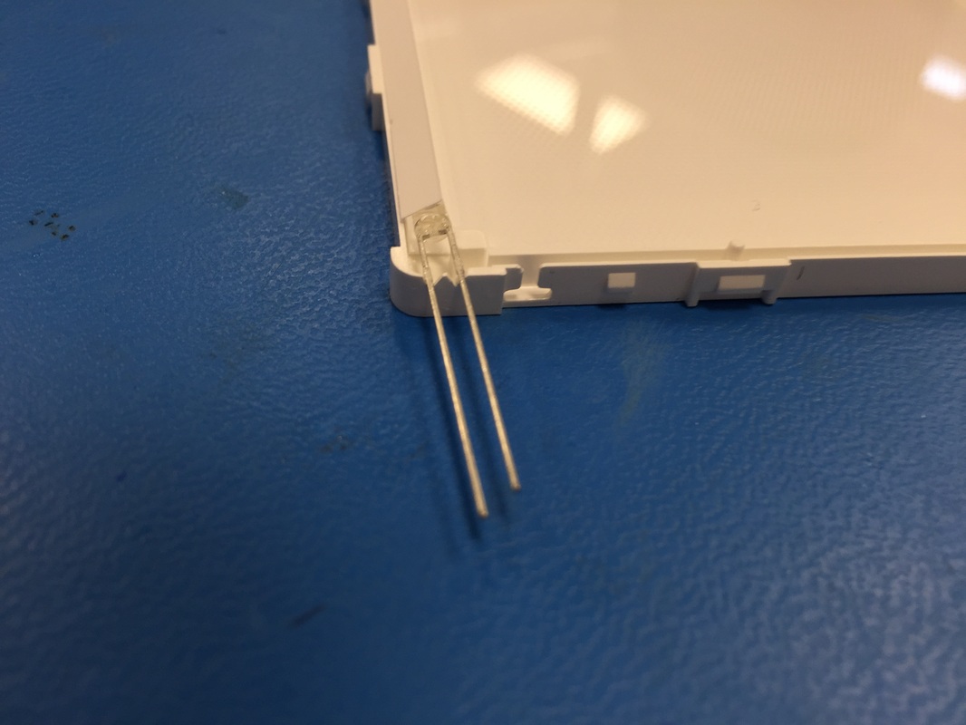
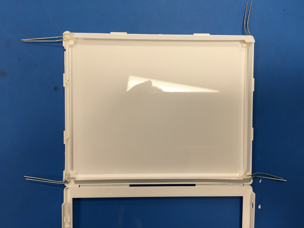
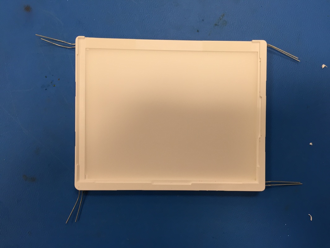
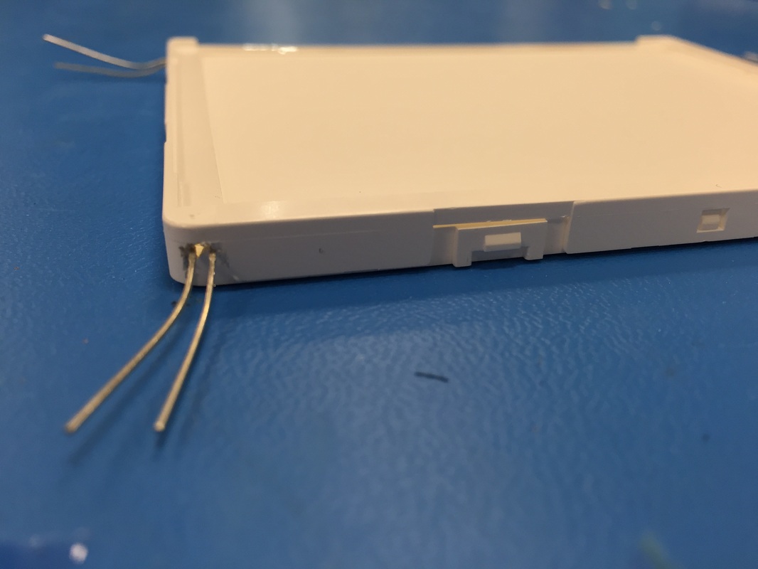
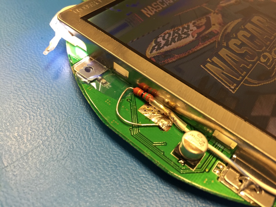
The PSOne screen comes with a florescent tube bent into fitting on 3 sides of the screen. I used the two guides from my last post to help me take that tube out and replace it with LED's. The guides say to use 3 LED's but I used 4, one at each corner. Cut slits into the light box (most of the screen is really just the lightbox, not the LCD itself) and sneaked out the leads. The end result is a bit underwhelming, I thought it would be brighter, but It's not too bad from head on, any other angle and its not too good. Used 4 LED's with Vf=3.2V, strung them in parallel with a 15ohm resistor on the low end. This gives me about 30mA across each diode which should be plenty bright as you can see from the bits leaking out the corner slits.
LCD screens work with a backlight. Older LCD's use a florescent tube as a backlight but newer ones use LED's because they are more power efficient. Watch this video for a bit of reference as to how they work.
The PSOne screen comes with a florescent tube bent into fitting on 3 sides of the screen. I used the two guides from my last post to help me take that tube out and replace it with LED's. The guides say to use 3 LED's but I used 4, one at each corner. Cut slits into the light box (most of the screen is really just the lightbox, not the LCD itself) and sneaked out the leads. The end result is a bit underwhelming, I thought it would be brighter, but It's not too bad from head on, any other angle and its not too good. Used 4 LED's with Vf=3.2V, strung them in parallel with a 15ohm resistor on the low end. This gives me about 30mA across each diode which should be plenty bright as you can see from the bits leaking out the corner slits.
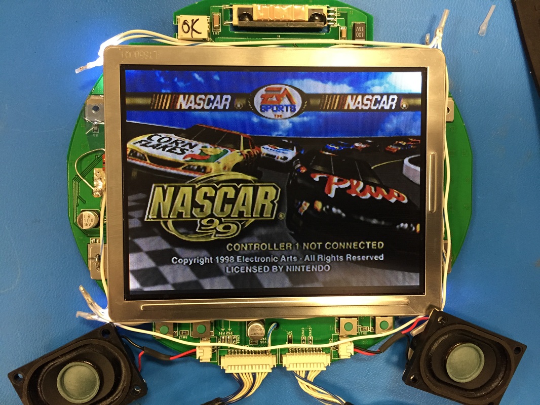
I noticed I could still control a bit of the brightness through the buttons on the board. Since the backlight is completely out the only explanation I could think of is that the screen color is being changed to a darker color rather than its brightness. This, coupled with the fact that its an old screen sorta makes me happy enough at how bright it is. I won't need brightness control for my console so just going to set it to the highest setting and leave it there.
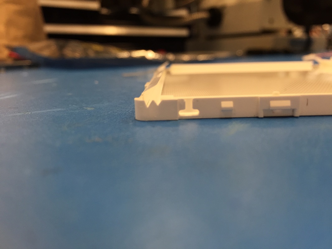
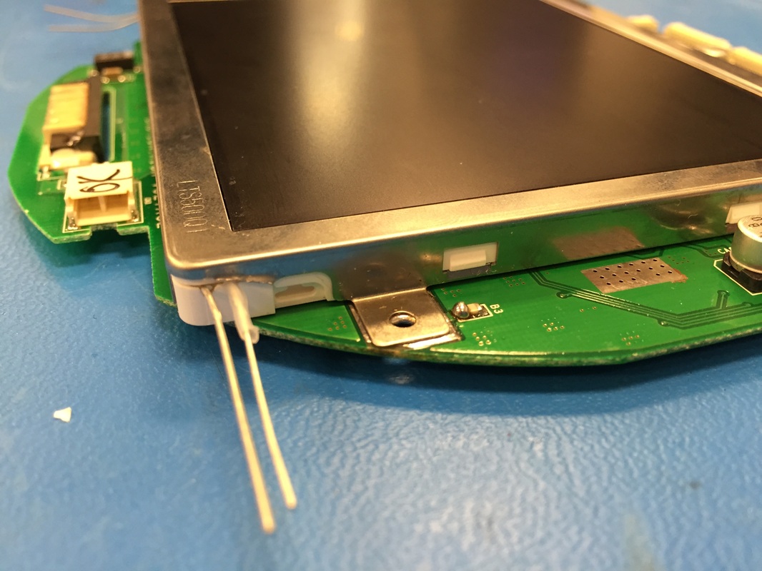
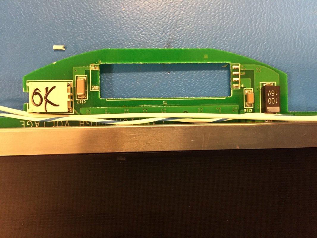
Take care to not short the leads of the LEDS together or to the case. I had to shear the metal case a bit as you can see to let the wires sneak through. Also desolder the transformer at the top since its not needed anymore. All together, the LEDs take 120mA. Add that to the 260mA that the screen takes with no backlight you get 380mA. This is way below the 600-900mA range that I observed before.
I'm also thinking of adding a switch to turn on and off the fans for power considerations, or maybe even get a 5V linear regulator to have them operate at full potential (or have a 3 way switch to choose between 3.3V, 5V, or off!)
Next Steps
-Schematics/block diagram
-Buy vibration motors
-Buy Coin cell battery
-Set up everything on the bench including the mosfets
-Plug in and test AV and extra controller jacks
-Finish up case (how do I hold the buttons in place?)
-Get back the PCB I ordered and wire it up to controller
