Oscillators
As I described in my last post, I was getting pretty bad timekeeping with the dinky 3pF crystal. It was gaining something like 2 seconds every hour. I attributed this to the giant mismatch of capacitive loads. So since then I've tried 3 other solutions: a 9pF crystal, a 1uA TCXO, and a 15uA oscillator. The 9pF was the tuning fork one I should last time. The system current draw was about the same ~45uA during sleep. Time stability was much better at +0.22 seconds/hour. I then found this awesome temperature compensated crystal oscillator (SIT1552AI-JE-DCC-32.768E) which claimed to draw 1uA and even when you add in all the driver current and load power it was supposed to be about 2uA. So I would have expected about ~47uA from the whole system. My watch died after `40 hours of use because the tcxo was drawing like 3mA! in that 40 hours it kept pretty good time only losing about 0.02 seconds/hour. Then I tried a last resort, going for a regular old oscillator (KX2511A0032.768000) which claims to draw 15uA max. That's not the best power, but I can handle it. It's only been running for 3 days now but its kept about the same 0.02 seconds/ hour as the TCXO. so my total system power with this last one is 56uA during sleep. The micro wakes up every 250ms for 10.6ms (730uA) to read ADC values and angles before going back to sleep. This gives an average power draw of 83uA with the 15uA oscillator whereas if the TCXO would work as expected I'd get something like 75uA. That 8uA is not the worst thing in the world to lose given how easy it was to get the normal oscillator going. Ultimatly I think overheated the TCXO when I reflowed it on a tiny breakout board I designed but I don't wanna take that chance with the board house. I also tried to do it again with a fresh part but while I was holding the board between my fingers to sand off the edge of the board I seem to have crushed the part. It's given me to much grief, I'm going with the reliable yet power hungry 15uA oscillator.
As I described in my last post, I was getting pretty bad timekeeping with the dinky 3pF crystal. It was gaining something like 2 seconds every hour. I attributed this to the giant mismatch of capacitive loads. So since then I've tried 3 other solutions: a 9pF crystal, a 1uA TCXO, and a 15uA oscillator. The 9pF was the tuning fork one I should last time. The system current draw was about the same ~45uA during sleep. Time stability was much better at +0.22 seconds/hour. I then found this awesome temperature compensated crystal oscillator (SIT1552AI-JE-DCC-32.768E) which claimed to draw 1uA and even when you add in all the driver current and load power it was supposed to be about 2uA. So I would have expected about ~47uA from the whole system. My watch died after `40 hours of use because the tcxo was drawing like 3mA! in that 40 hours it kept pretty good time only losing about 0.02 seconds/hour. Then I tried a last resort, going for a regular old oscillator (KX2511A0032.768000) which claims to draw 15uA max. That's not the best power, but I can handle it. It's only been running for 3 days now but its kept about the same 0.02 seconds/ hour as the TCXO. so my total system power with this last one is 56uA during sleep. The micro wakes up every 250ms for 10.6ms (730uA) to read ADC values and angles before going back to sleep. This gives an average power draw of 83uA with the 15uA oscillator whereas if the TCXO would work as expected I'd get something like 75uA. That 8uA is not the worst thing in the world to lose given how easy it was to get the normal oscillator going. Ultimatly I think overheated the TCXO when I reflowed it on a tiny breakout board I designed but I don't wanna take that chance with the board house. I also tried to do it again with a fresh part but while I was holding the board between my fingers to sand off the edge of the board I seem to have crushed the part. It's given me to much grief, I'm going with the reliable yet power hungry 15uA oscillator.
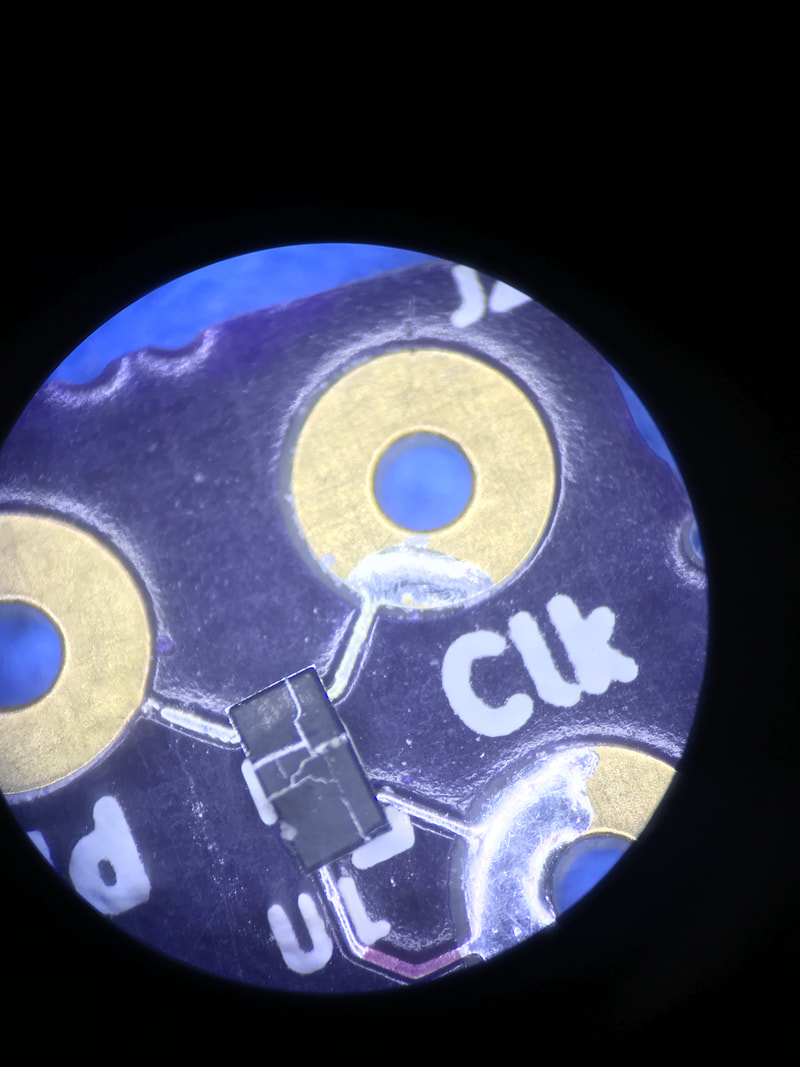
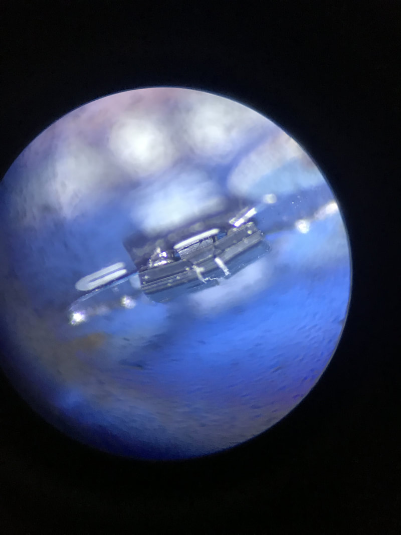
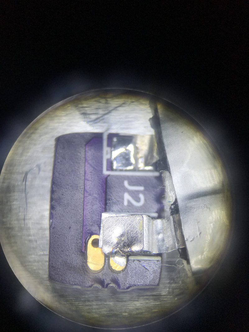
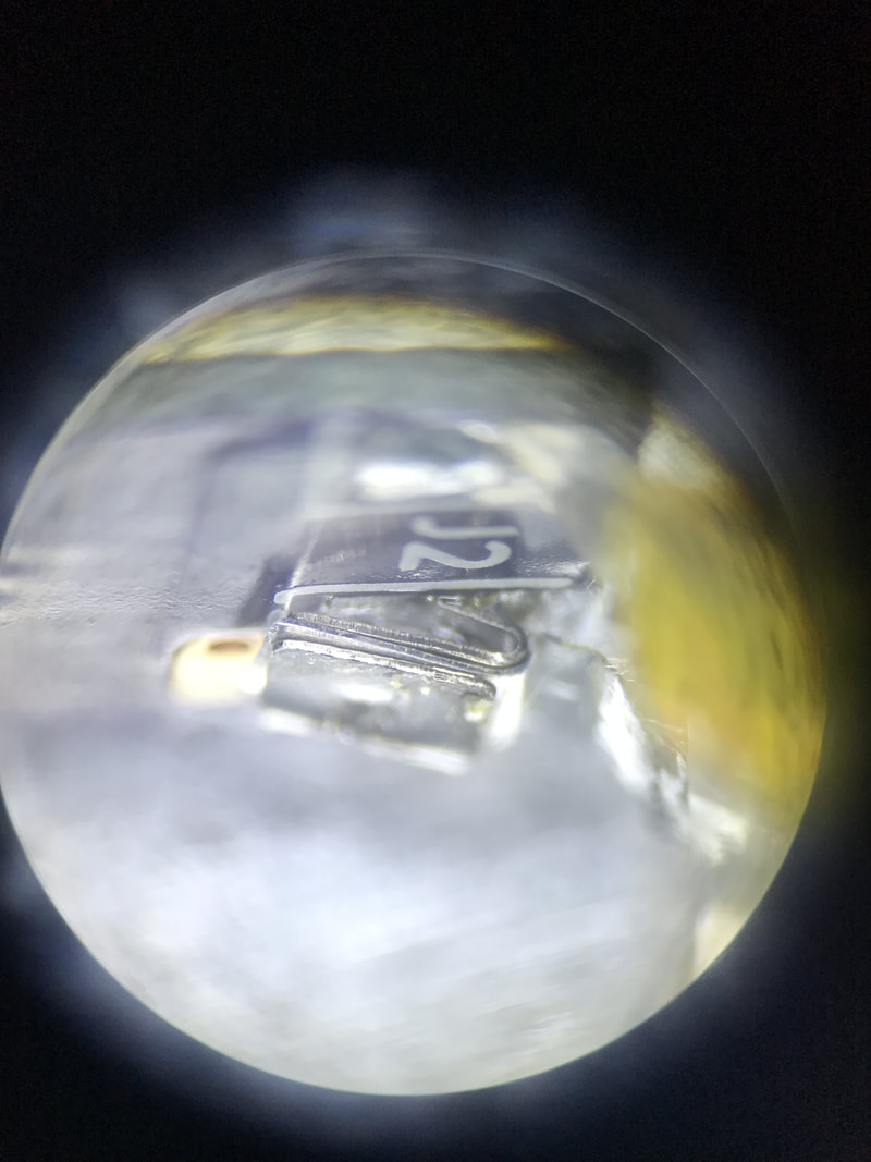
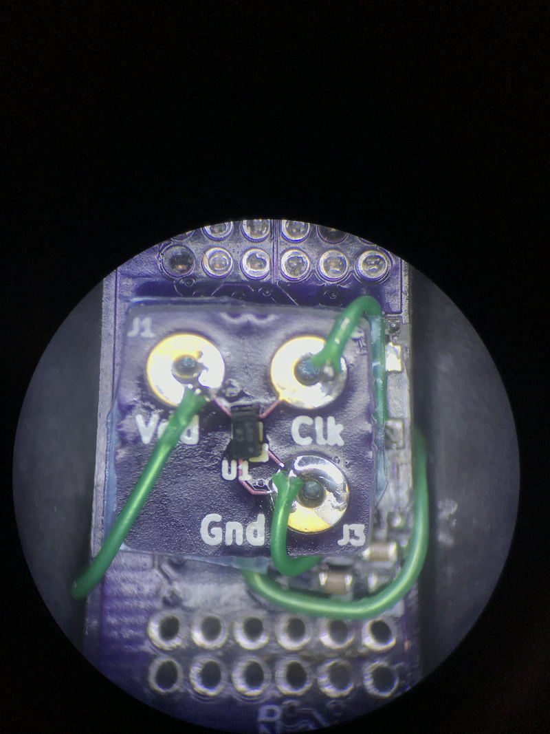 The TCXO on the tiny breakout board glued to the top of the microController | 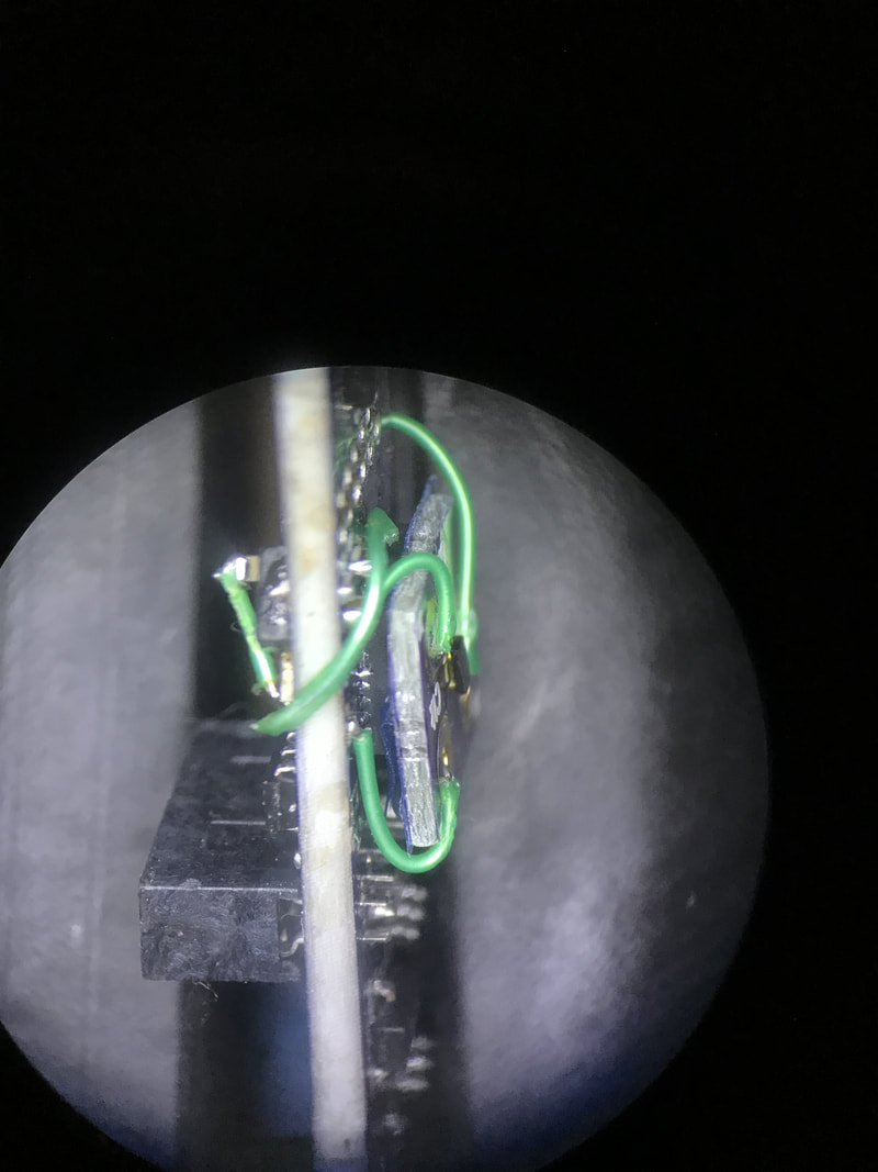 Side view of the TCXO. Gnd to gnd, 3v3 straight from the LDO, and clkout to pin 7 of the micro | 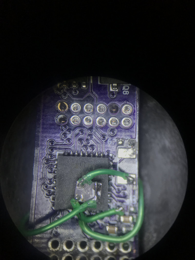 The normal oscillator deadbugged ontop of the micro. Nice big pads make it easy to work with. | 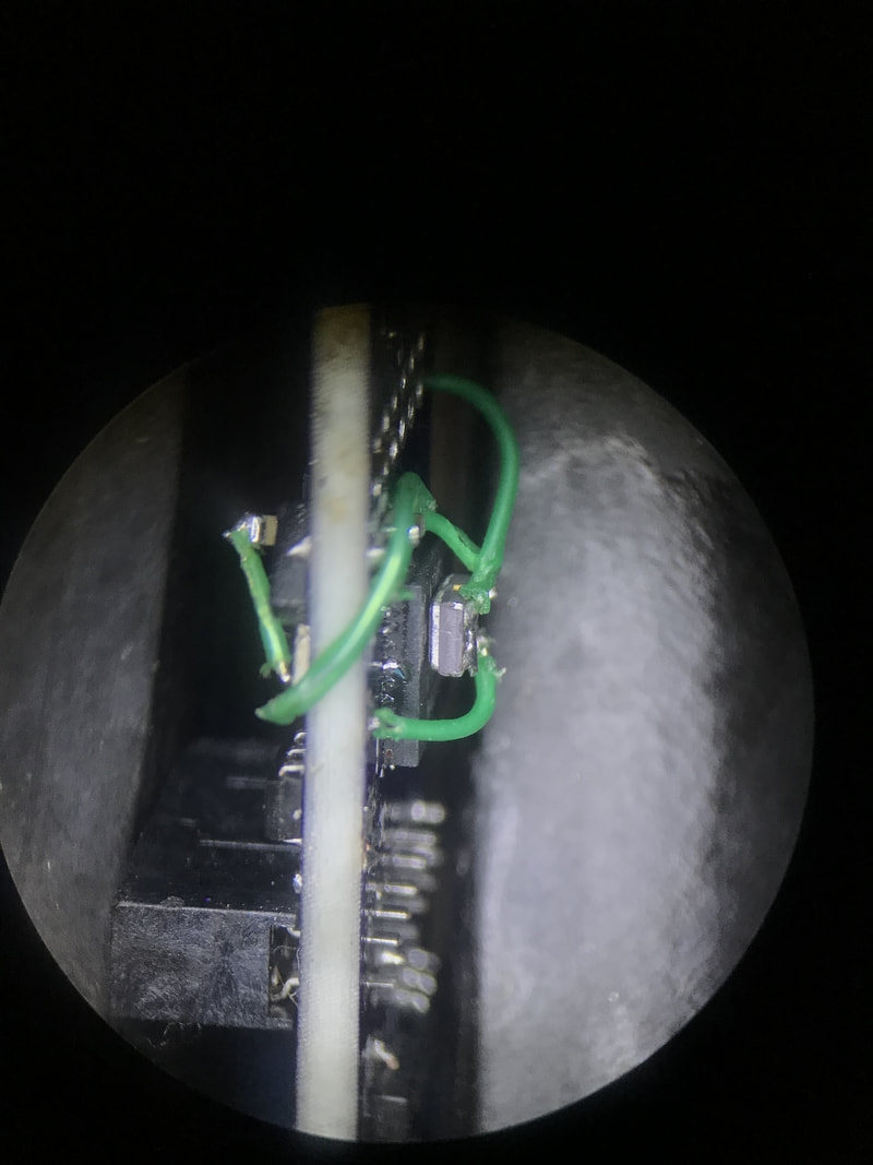 Side view of the oscillator. Same connections as with the TCXO. hard tied its enable to 3v3 |
My timer code now looks like this:
ASSR |= (1<<EXCLK); //enable external clock mode for oscillator instead of crystal
ASSR |= (1<<AS2); //TIMER IN ASYNC MODE so its decoupled from system clock
TCCR2A = (1<<WGM21); //set mode to CTC
TCCR2B = (1<<CS22) | (1<<CS21); //prescaler 32768/256 =128 per second
TIMSK2 = (1<<OCIE2A); //unmask the timer0_compA for interrupt service
OCR2A = 31; //set the counter value, (128-1)=1 second, (64-1)=twice a second, (32-1)=thrice a second
sei(); //enable global interrupt
_delay_ms(500); //give the timer circuit enough time to get itself going before we might go to sleep
Stability of Time
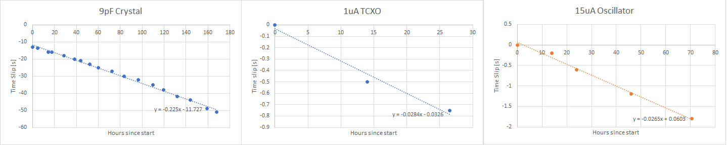
Below you'll see the long term slips each crystal/oscillator. The 1uA TCXO died after 40 hours so I didn't get to take more than 3 measurements. The oscillators are both 20ppm I think. which corresponds to 60 seconds / 35 days. Current the 15uA oscillator is showing 0.02 seconds / hour which works out to 60 seconds / 96 days. That exceeds my goal so I'm pretty happy with it
Below you'll see the long term slips each crystal/oscillator. The 1uA TCXO died after 40 hours so I didn't get to take more than 3 measurements. The oscillators are both 20ppm I think. which corresponds to 60 seconds / 35 days. Current the 15uA oscillator is showing 0.02 seconds / hour which works out to 60 seconds / 96 days. That exceeds my goal so I'm pretty happy with it
3v3 rail
Here is how the 3v3 LDO acts depending on the input voltage from the battery. Seems like the LDO never really pushes out 3v3 and tops out around 3.25v. Either way, this will help set the limits of operation and what 0% battery means.
Here is how the 3v3 LDO acts depending on the input voltage from the battery. Seems like the LDO never really pushes out 3v3 and tops out around 3.25v. Either way, this will help set the limits of operation and what 0% battery means.
|
|
Misc
- I got a 220uF tantalum cap (T520B227M006ATE025) for the input to the boost converter. Now i think the only voltage droop is the drop across the battery protection sense resistor which is saddening. I'm still seeing about 600mV drop. The 3v3 doesn't seem to be affected but this 600mV helps to determine when I should not be firing the tubes anymore and just ask to be charged.
- I added a 220k pullup to the LDI pin of the boost converter because I missed it on the datasheet.
- I was seeing that sometimes the boost converter wasn't able to get all the way up to the 180v and would die too early. Attributed that to being too quick on the trigger. Now I wait 10ms between turning on the converter and trying to use the power. I've shown before that the 180v is achieved within like 1ms so I can probably scale that back but even 10ms is not noticeable
- The 10.6ms out of every 250ms the micro is awake is mostly the 10ms delay I have so that the accel voltages can settle. I could play some game where I wake up 10ms earlier to turn on the accel then fall asleep and come back to read the adc's but screwing with interrupt timing is a little messy and I don't think I stand to gain too much power savings.
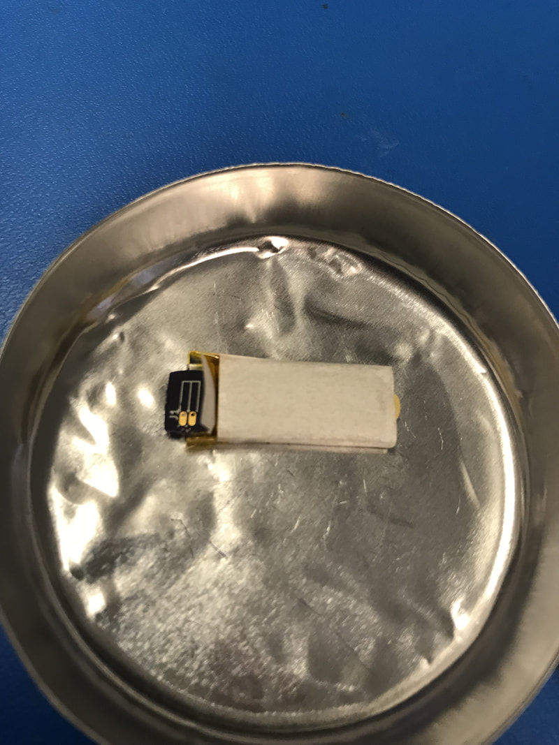
- I tried my to prepare a second battery by soldering the tabs to a new 31mil thick connector pcb. Had trouble with the tabs bending since one had a spot welded extender and ended up shorting the terminals together. No smoke but the battery got pretty warm. It was shorted for a good 20 minutes but when I desoldered the connector board the lipo showed 700mV across it, probably due to the copper/aluminum galvanic cell.
 |  |  |  |  |
Next Step:
Finish with a few more days of recording the time slip on the oscillator then the big step of actually soldering the tubes and PCBs together and fitting them in a case. I'll be adding 1 more LED to the power board so it looks like a proper colon between the hour and minute. Otherwise it's all ready. This will be a big step so I'm a little nervous about messing up tubes or parts. But hopefully next post I'll have a nice solution in a case for you guys!
Finish with a few more days of recording the time slip on the oscillator then the big step of actually soldering the tubes and PCBs together and fitting them in a case. I'll be adding 1 more LED to the power board so it looks like a proper colon between the hour and minute. Otherwise it's all ready. This will be a big step so I'm a little nervous about messing up tubes or parts. But hopefully next post I'll have a nice solution in a case for you guys!
