Assembling the Watch
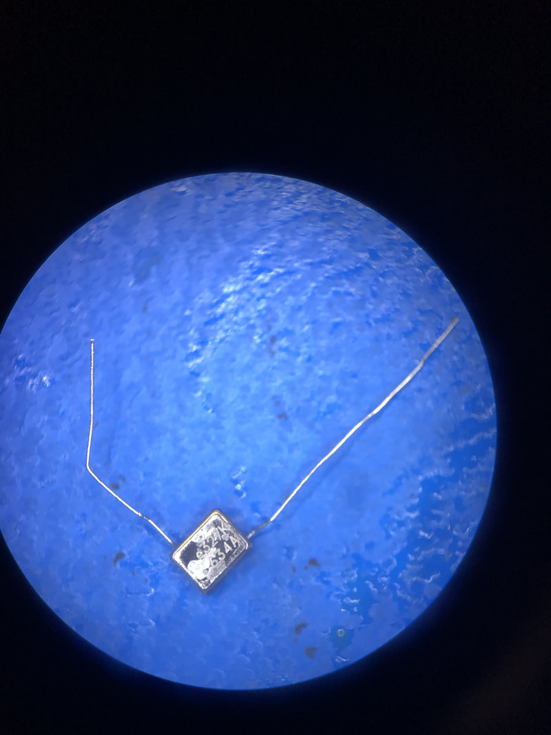
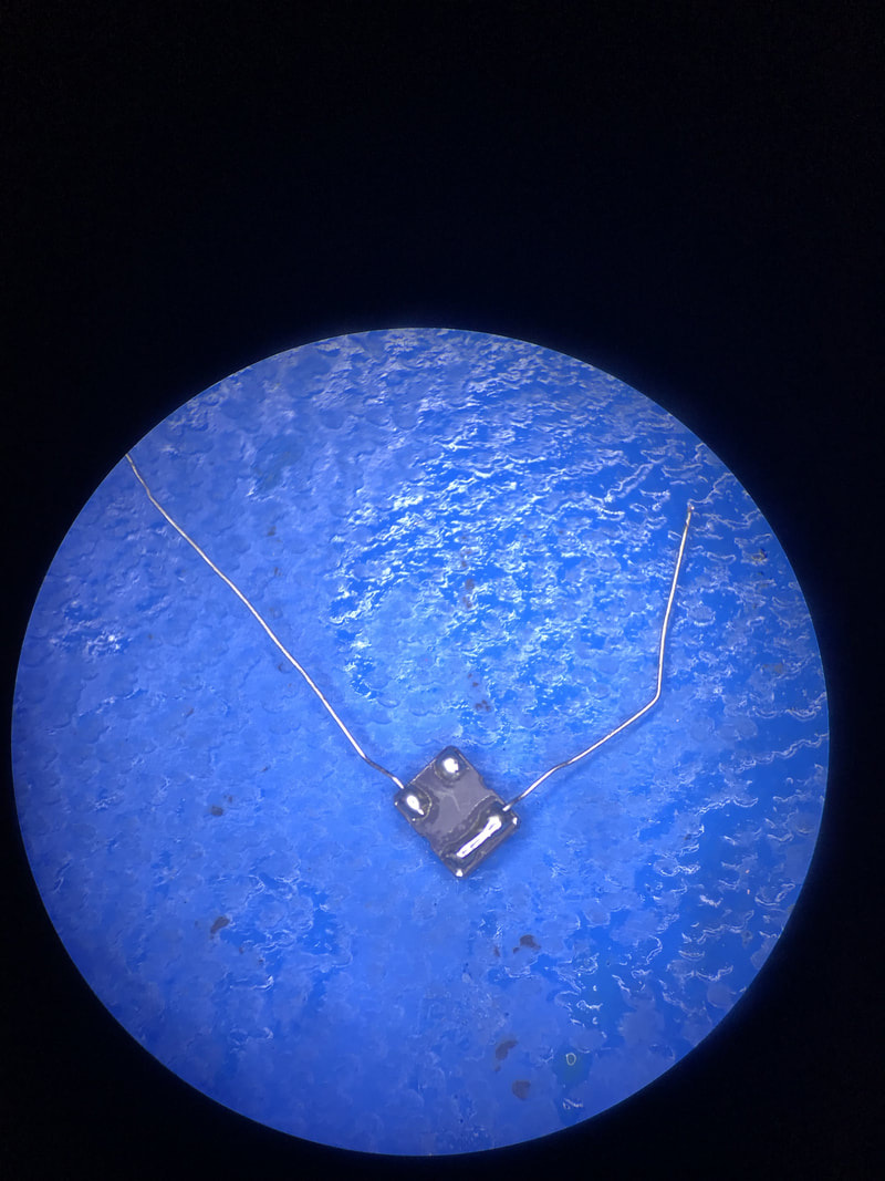
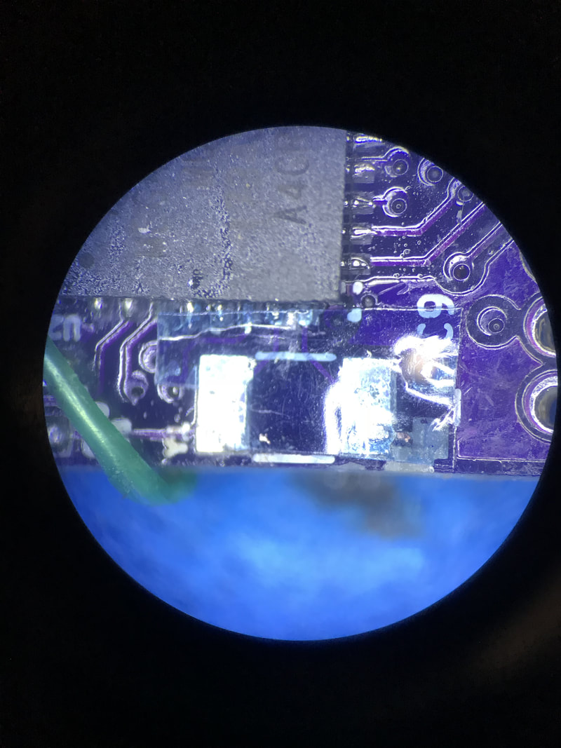
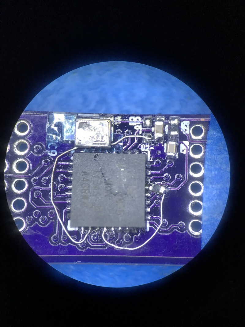
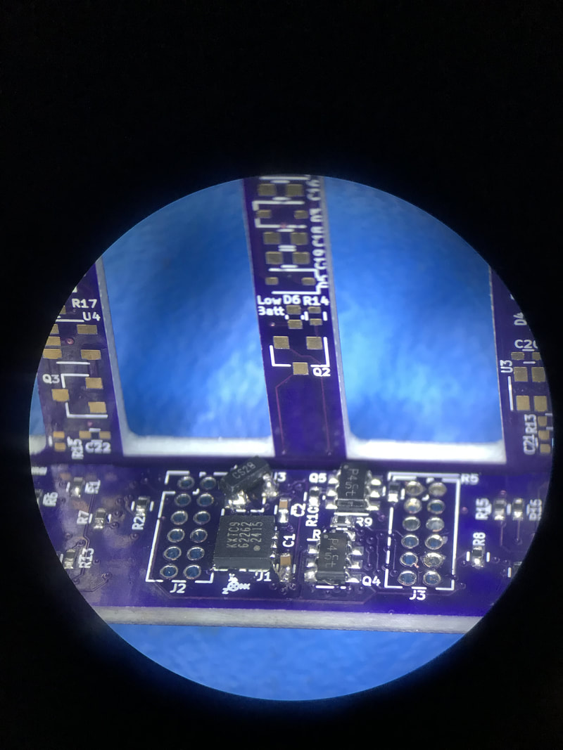
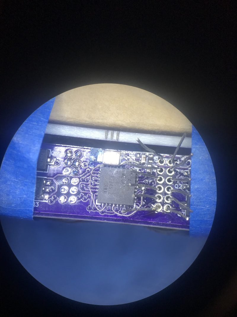
One of the biggest changes since last post has been soldering everything together to be able to fit into the 3D printer case. I began with making the changes I had done to the logic board more discrete by replacing the white/green wires with 36 AWG wire strands. Then I was able to solder the oscillator and reset pullup in place
One of the biggest changes since last post has been soldering everything together to be able to fit into the 3D printer case. I began with making the changes I had done to the logic board more discrete by replacing the white/green wires with 36 AWG wire strands. Then I was able to solder the oscillator and reset pullup in place
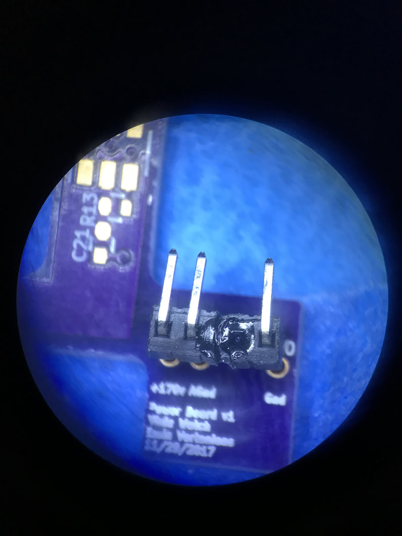
I then used one of the blank power PCBs to hold headers in place while I glued them at the right distance from each other. Not the prettiest but its the most precise. Once the headers were made I was able to fit check the logic board with the main board, solder the headers to the logic board and set up for soldering the tubes.
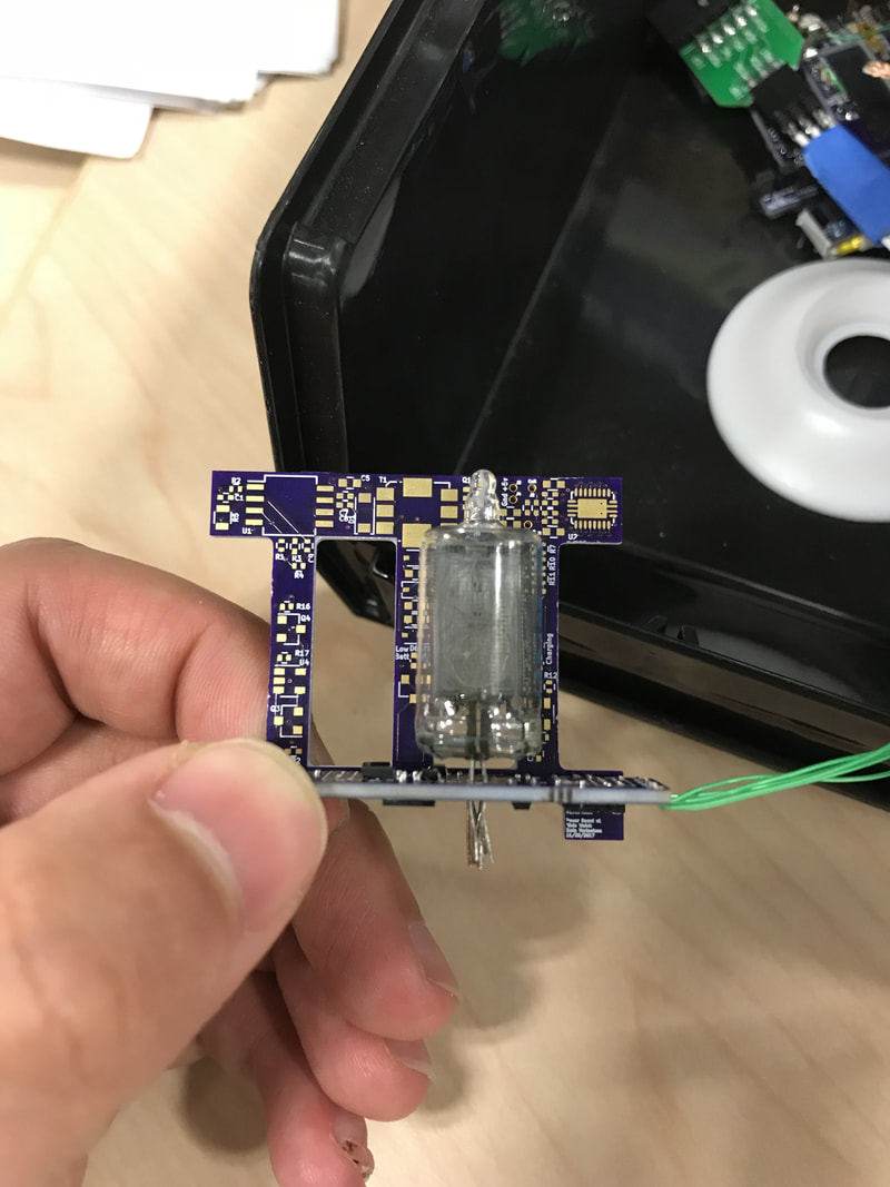
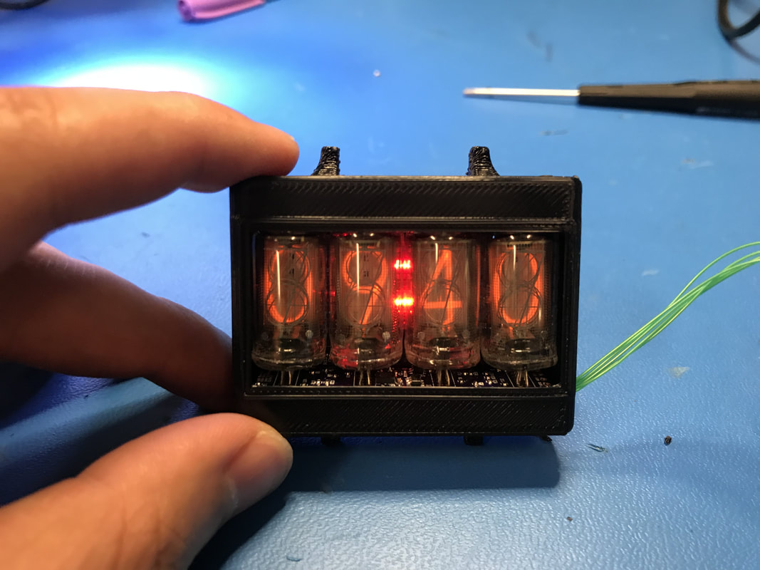
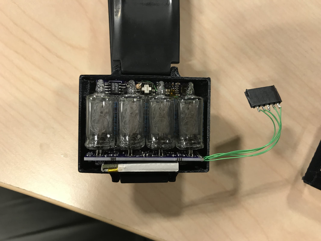
Next came the delicate task of fitting the tubes inside the holes as flush with the board as I could. I used the blank power PCB again to line myself up so that all the boards were the same height. I taped them down, quickly tacked the two end leads down on each tube then came back around and soldered everything correctly. Took a while and needed a lot of cleaning. You have to be really careful with not heating up the leads for too long, the metal can expand and create micro-fractures in the glass which lead to a leak after a few days. As you can tell, the logic board isn't exactly perpendicular to the tubes, but it'll do for now.
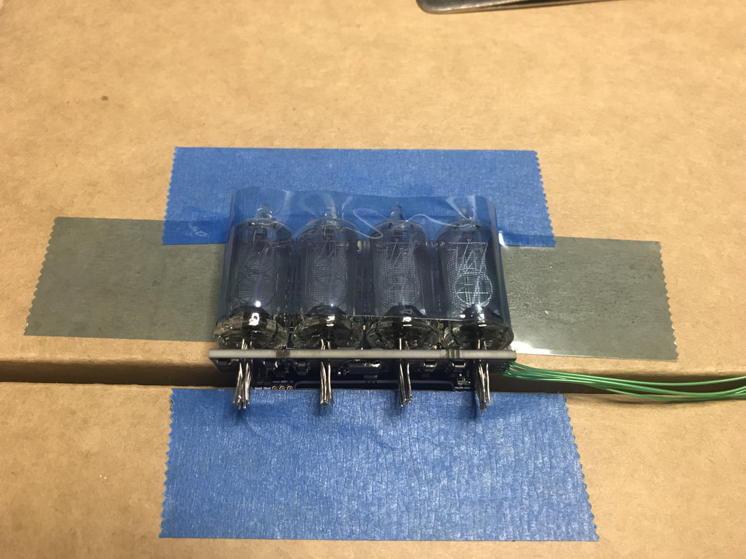
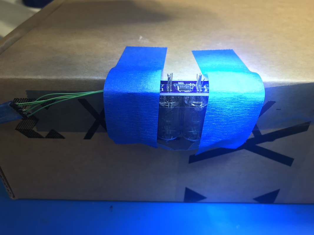
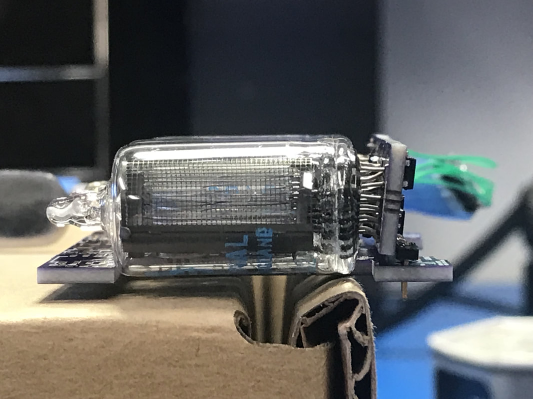
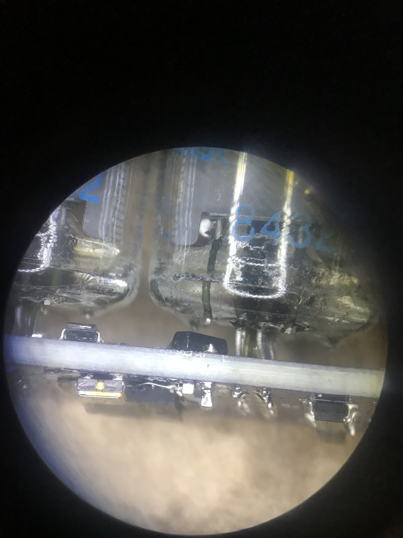
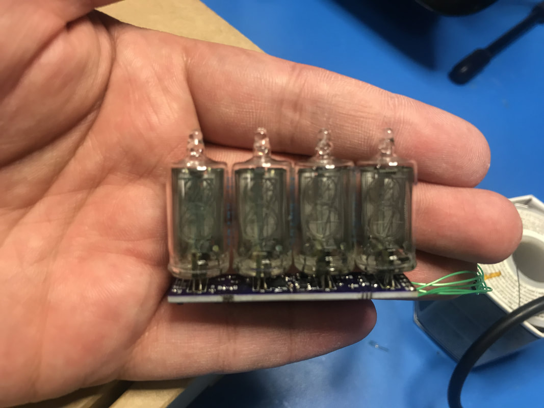
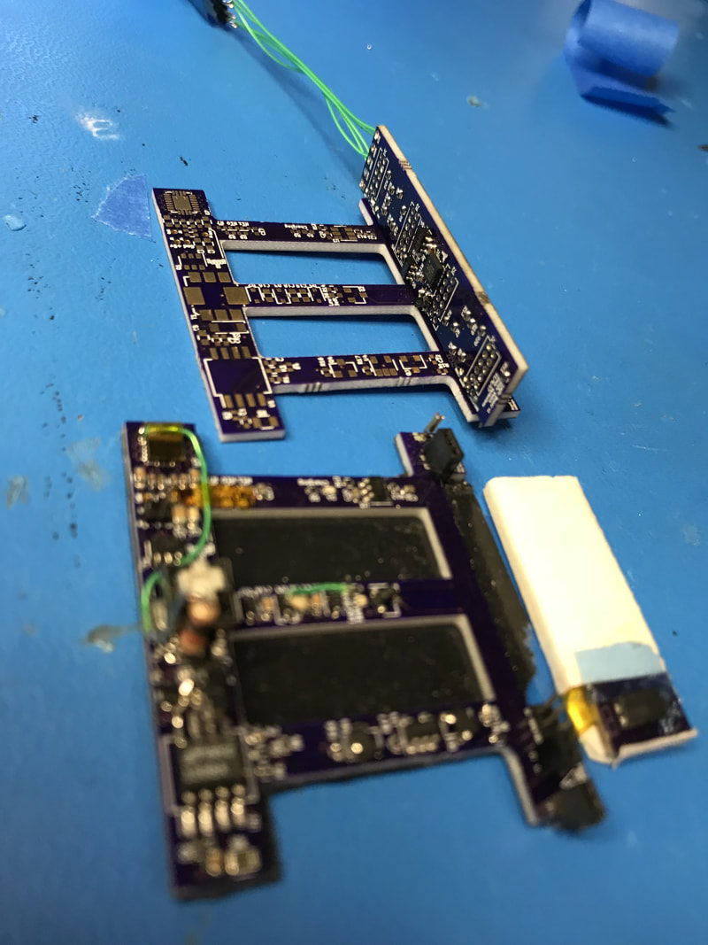
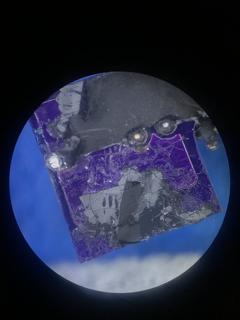
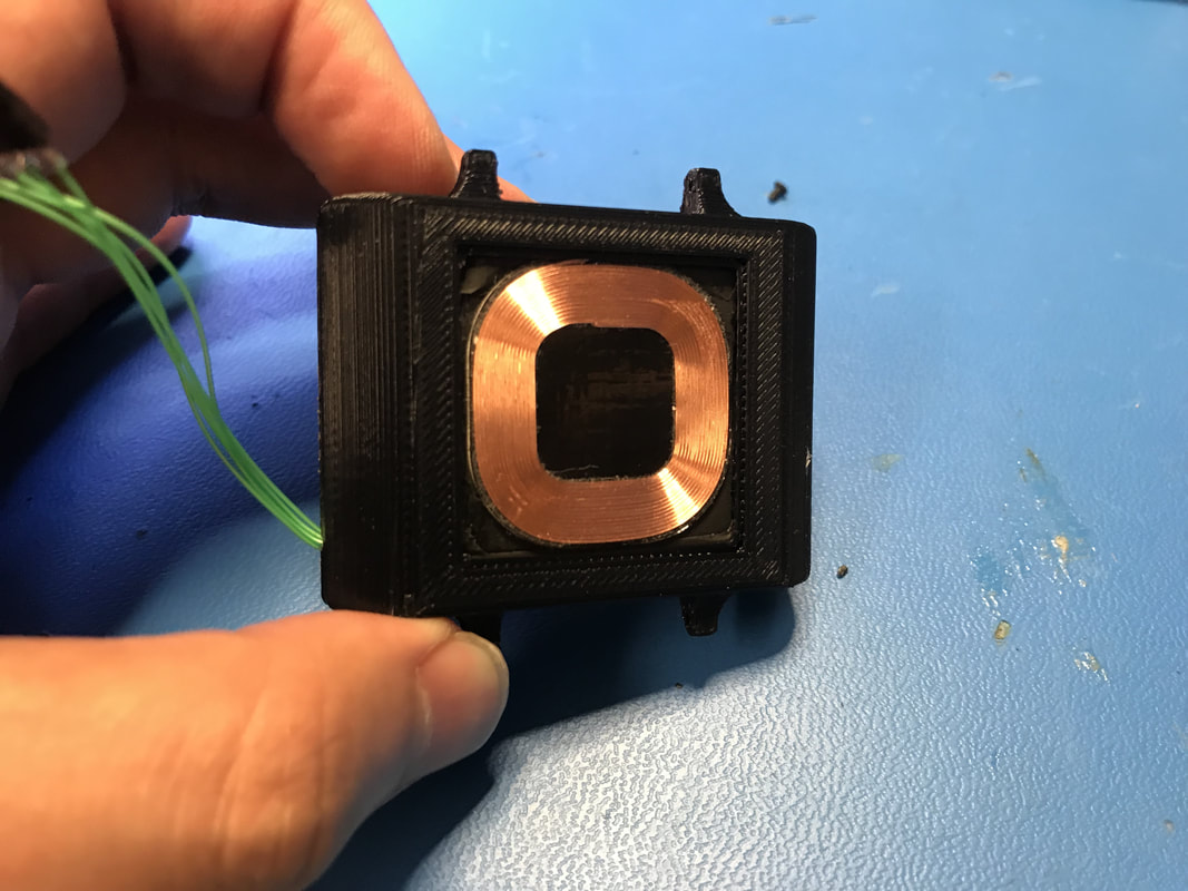
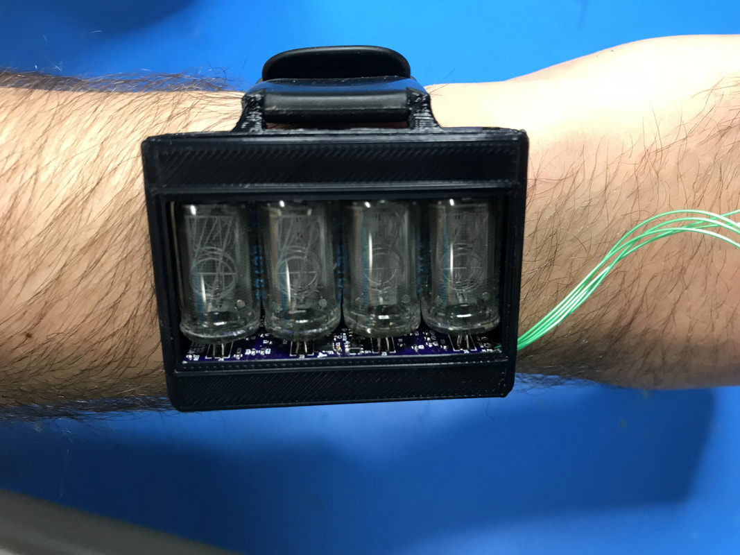
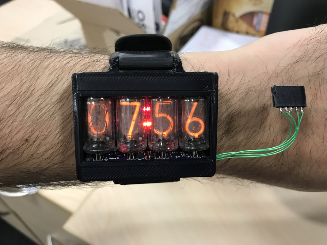
After the logic board was all done, I tested it by plugging into the headers on the power board. When I was sure all the connections were going to hold, I desoldered the headers and soldered the logic board to the power board in their final configurations. I had to make sure the tubes fit inside the cutouts I had in the power board, I think I can do better on the next watch, this works well for now. I also had to replace some of the ferrite sheet, check out how it flakes off, almost like a ceramic piece of magnet! In the end, the watch was wearable right then and there.

I'll have to make the video describing how to use it and everything. Will show it off fully once all the hardware problems are identified and software is done. I wanna make a video as a kickstarter for like 10 builds to fund the endeavor. I've already gotten like 4 or 5 "pre-orders" from friends so we're looking good for the first batch!
Case
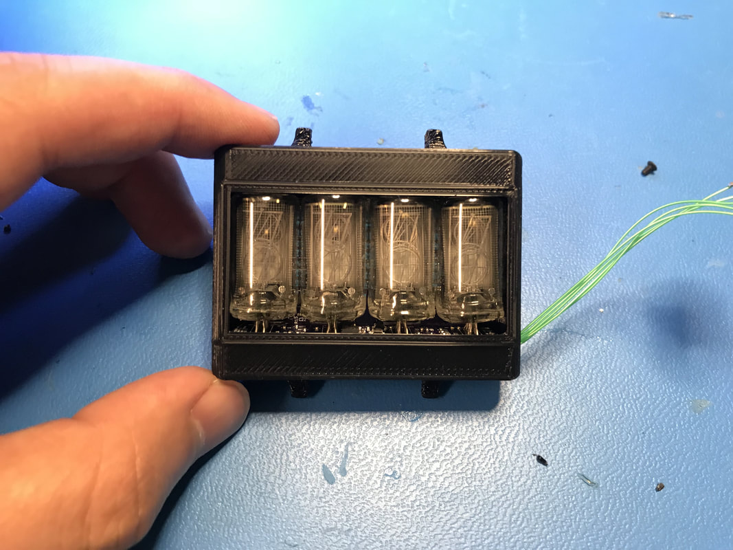
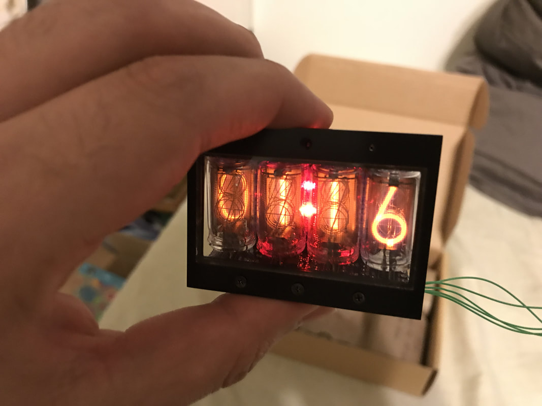
The case, ordered at 3DHubs, was gonna be too expensive to manufacture fully so I ordered 3 test pieces of a flat 1mm thick piece with the cutout for the front window and some tapped and countersunk holes to test out their capabilities. I also asked for black anodization which looks great! really impressed with their work. The glass I got from SI Howard Glass Co which did an amazing job with their 22 mil thick gorilla glass. I got 20 sets of these so I'll likely use these for the final product. I naively didn't include any tolerance on the glass dimensions so the cutout in the case is EXACTLY what the glass lengths are which means it doesn't fit, that's why you see cracks along the border. I'll have to widen the window opening by like half a millimeter for the final case. For now, it looks legit.
The case, ordered at 3DHubs, was gonna be too expensive to manufacture fully so I ordered 3 test pieces of a flat 1mm thick piece with the cutout for the front window and some tapped and countersunk holes to test out their capabilities. I also asked for black anodization which looks great! really impressed with their work. The glass I got from SI Howard Glass Co which did an amazing job with their 22 mil thick gorilla glass. I got 20 sets of these so I'll likely use these for the final product. I naively didn't include any tolerance on the glass dimensions so the cutout in the case is EXACTLY what the glass lengths are which means it doesn't fit, that's why you see cracks along the border. I'll have to widen the window opening by like half a millimeter for the final case. For now, it looks legit.

Ghosting
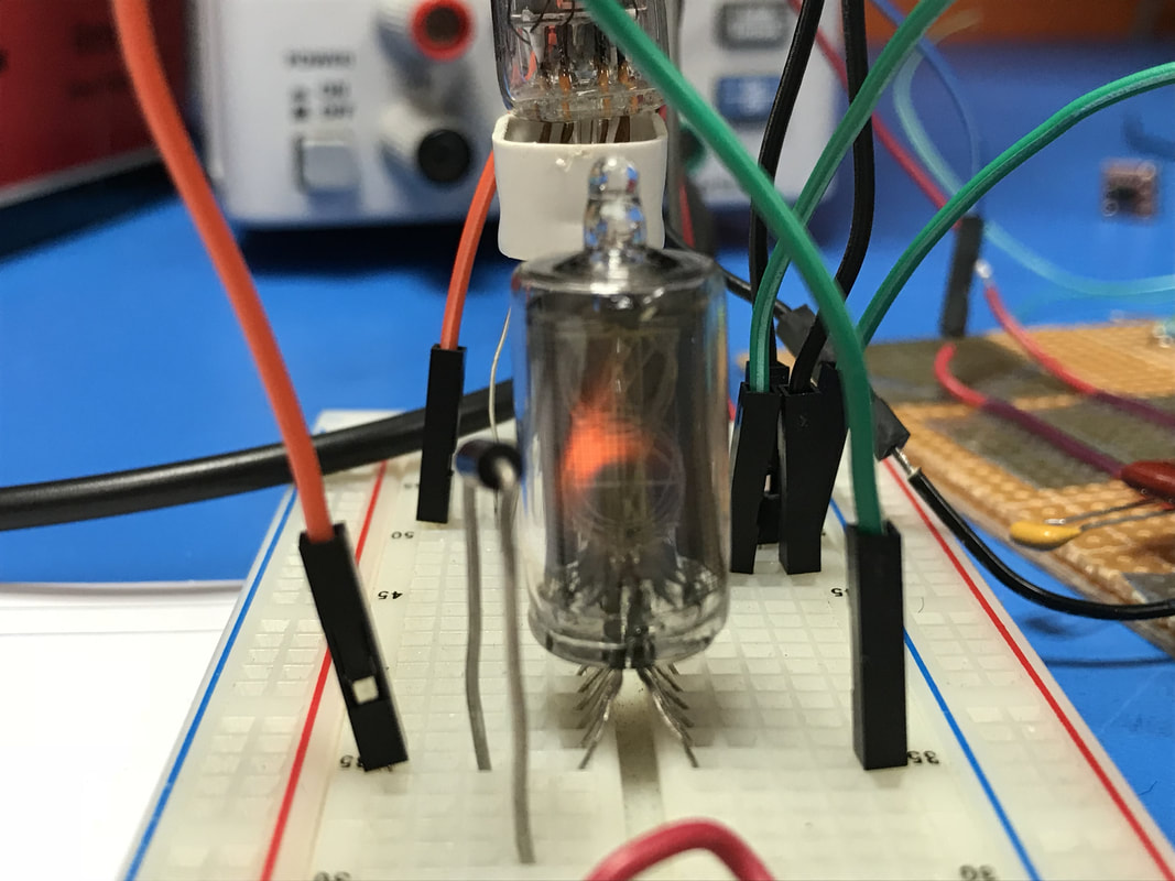
I talked about this issue a few months ago when I had just two tubes lit on the breadboard. While one tube is off, I get ghosts of the other tube's lit number appearing on the off tube. People have talked about this a bunch, here is what I have found from first hand testing.
I talked about this issue a few months ago when I had just two tubes lit on the breadboard. While one tube is off, I get ghosts of the other tube's lit number appearing on the off tube. People have talked about this a bunch, here is what I have found from first hand testing.
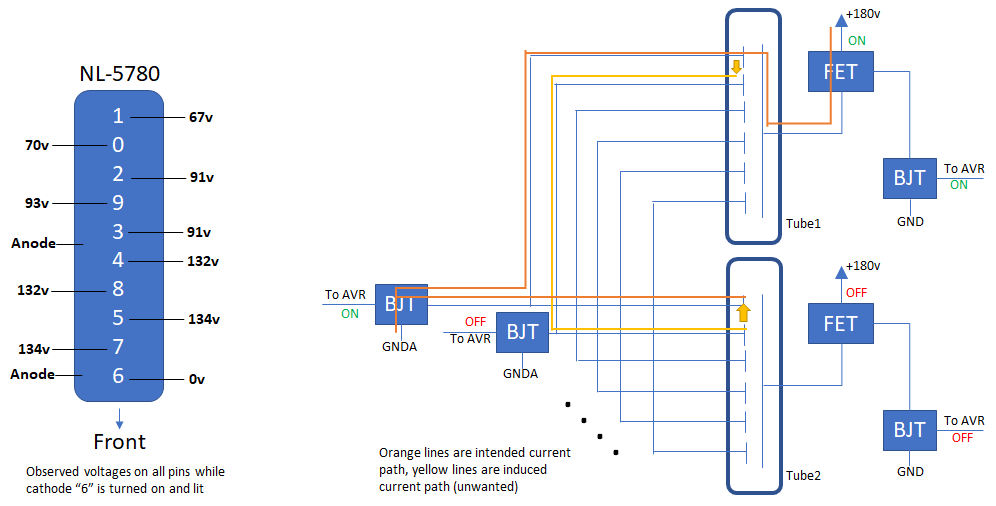
- A tube's numeral can be lit in the normal way. 180v on anode, 0v on cathode. This is how most people's circuits are intended to work
- A tube can be lit if you ground a certain cathode and apply 180v to a numeral that's near the grounded cathode. So cathode "6" is grounded and cathode "5" is held at 180v, that'll make "6" glow. I reckon it's not correct though
- When a cathode is lit, say a "6", the numbers around them will develop a high voltage. So "7, 5, and 8" could all sit well above 120v!
- If a tube's cathode is at ~120v its anode stays around 0v.
- Lastly, when a cathode is held low and its anode connected to a revere biased diode to mimic the body diode of a FET, the tube lightly turns on when 180v is applied to the cathode of the diode. This effect is super unreliable but definitely observed.
 |  | 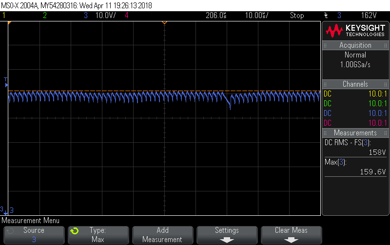 |
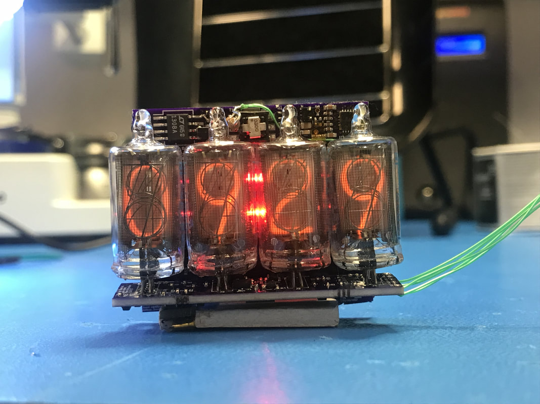
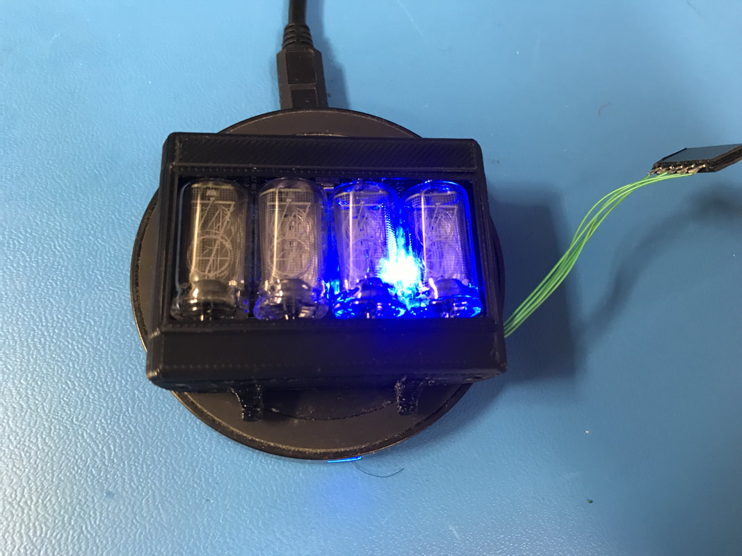
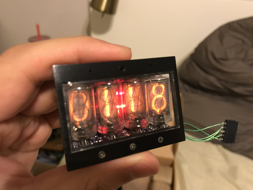
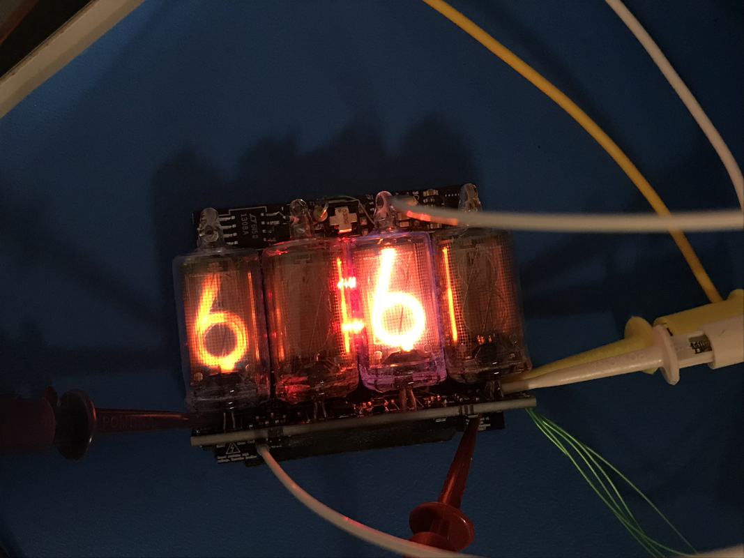
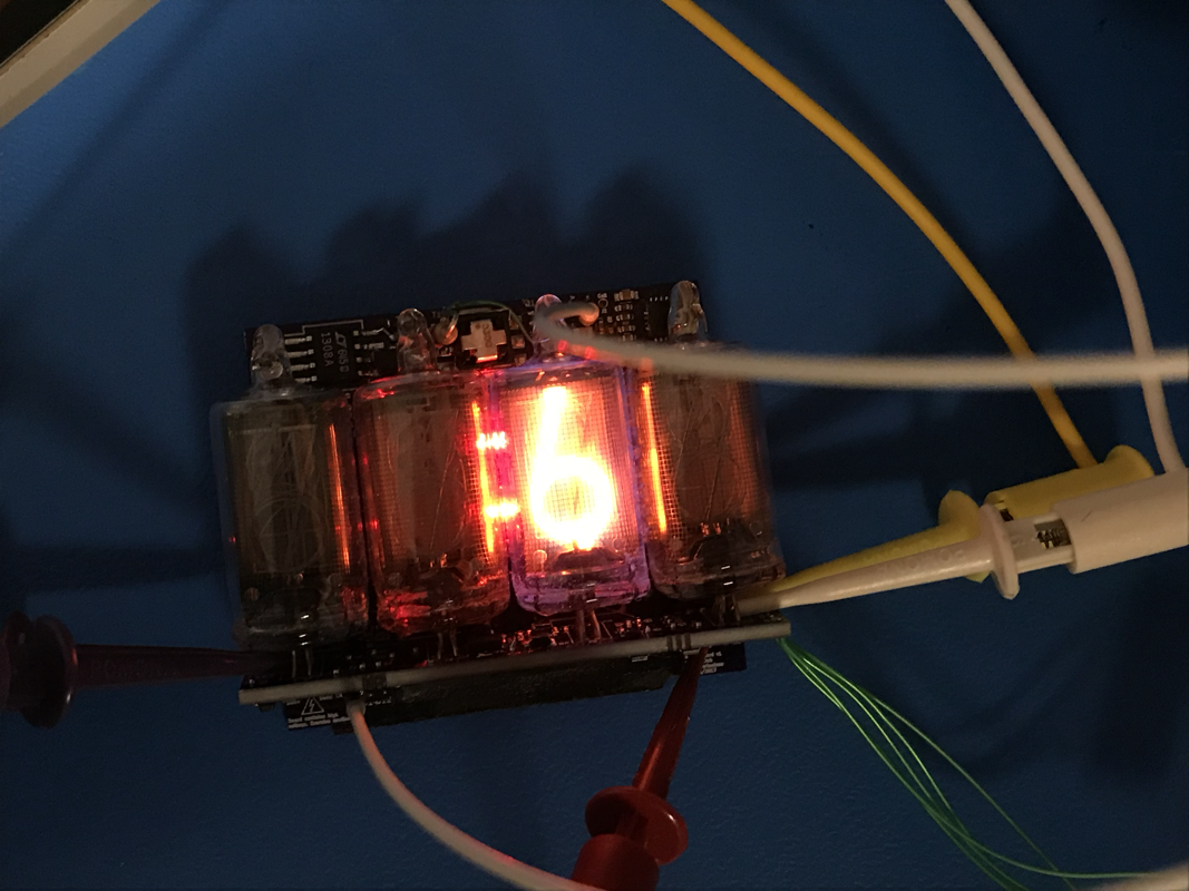
I tried what every other legit Nixie clock maker has done and added 51v zeners to the cathodes. On my watch, I had to add 51v zeners to numerals "7, 5, 8, and 4" while lighting "6" to get all ghosting to stop. Below you can see me having turned on the “6” on tube 3 (not pwm-ing or anything, just on) and ghosts appearing in tube 1. Next to that is a shot with the zeners engaged, no more ghosts. Although then I was inducing very faint ghosts of the listed numbers in the lit tube. Also note that you have to tie those zeners back to the GNDA instead of GND since GNDA feeds back to the extra 150 ohm resistor that corrects the feedback voltage of the boost converters. If you just connect to GND then you'll suck way more current bleeding off the residue charge. Each 51v zener seemed to conduct about 130uA of current which is a lot of extra juice at high voltages. The above scope plot shows the voltage at like 160v while the tube is on with the zeners. I don't like that too much, seems too high which could explain the excessive ghosting. Anyways, I'll consider putting in zeners on the logic board for the production models, it's getting too crowded there though and I've been told "the ghosting gives it an authentic look, like it's not 100% perfect since its old." I don't know, we'll see.
Power Draw
The watch's regulator draws way too much power while lighting a numeral. On the watch I read ~370mA to light a "6" while on the stand alone regulator board I used for pathfinding I draw like 120mA. I really hope the culprit is that the feedback pin is simply registering a different voltage on the dividers and drawing more current. Pulling almost 400mA is bad for the battery as well as battery life. This is basically the last thing I have left to do before I call this prototype done.
I also had a big scare while doing sleep power measurements on the whole watch. Before I had soldered everything together I was seeing sleep power numbers of about 55uA, waking up for 10ms at like 760uA then going back to sleep for an average pull of 83uA. When I measured sleep current draws I saw I was pulling more like 150uA in sleep and like 1200uA during on. After a ton of panicking I realized the charge pin is my culprit. I pull the charge pin low to signal to the wireless receiver that I'll take charge anytime you give it. Well that's got a fat 50k pullup to batt+. I was sinking 4.2v/50k = 84uA just to keep that communication going! I pulled that high and I went back to ~75uA when asleep and 1125uA awake which is the sad best I can do with this prototype. The AVR can only drive the pin high to 3v3. Well that's (4.2-3.3)/50k = 18uA more than I want (~55uA is my desired and I'm getting 75uA). The final model will have this fixed but unfortunately my prototype will forever be wasting 18uA of power for no reason.
Misc
- I've found that every time I plug the battery in and go through the normal routine of shorting Batt- and Gnd the accel doesn't work well. I think something in the startup transient and its interaction with the AVR puts it in an unhappy state. My standard practice has become to hold the AVR in reset as I plug the battery in and short the Batt-/Gnd. This has a 100% success rate as far as I can tell with the accelerometer. I may add a pulldown to the enable line of the accel for production.
- If you noticed up above I added a second red LED in the middle of the watch to form a colon with the original red LED. I was originally going to use the single red LED as a low battery indicator but have since decided a colon is more appealing and natural.
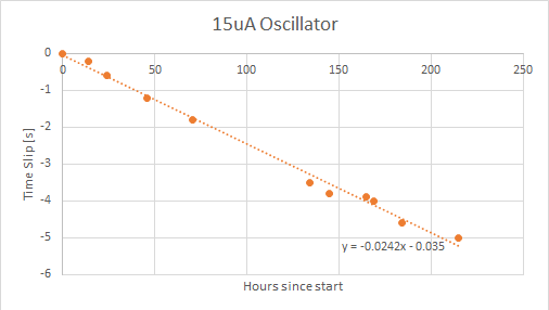
- The final timeslip numbers are presented in the below file. The 15uA oscillator was really damn precise (like +/- 7ppm) so I'm happy I made the jump.