It's been such a long time
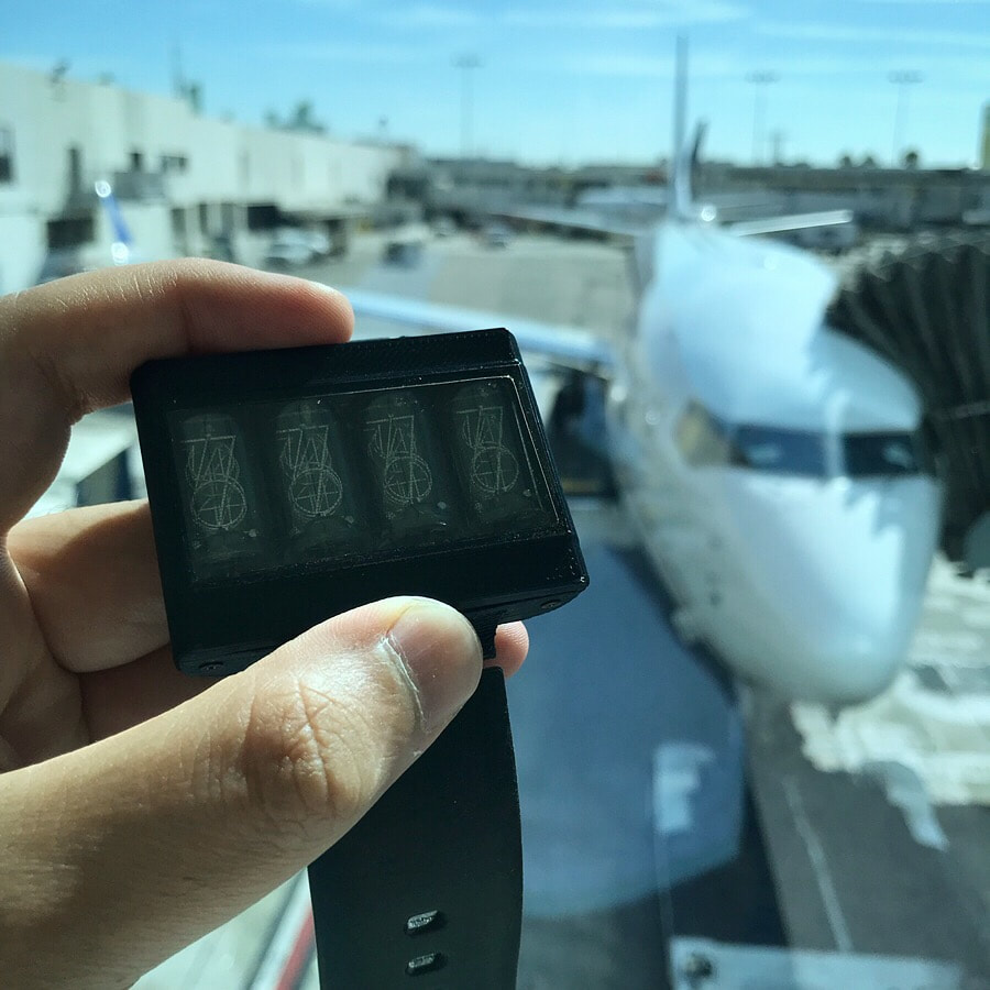
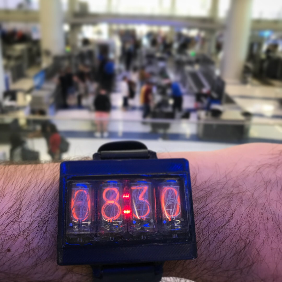
Sorry for dropping out guys. Work and life got in the way and thanks to COVID and work ramping down a bit I've been able to pick this puppy back up. Since last time I've had a ton of new stuff happen that I just didn't post about. I ordered metal boxes from 3Dhubs, I ordered the production boards from some Chinese company in Shenzen, I had it all working in a metal case and wore what you see as my primary watch for more than a year! I'm ready to dive back in and finish up the tiny imperfections with this design so we can move to selling a few.
Sorry for dropping out guys. Work and life got in the way and thanks to COVID and work ramping down a bit I've been able to pick this puppy back up. Since last time I've had a ton of new stuff happen that I just didn't post about. I ordered metal boxes from 3Dhubs, I ordered the production boards from some Chinese company in Shenzen, I had it all working in a metal case and wore what you see as my primary watch for more than a year! I'm ready to dive back in and finish up the tiny imperfections with this design so we can move to selling a few.
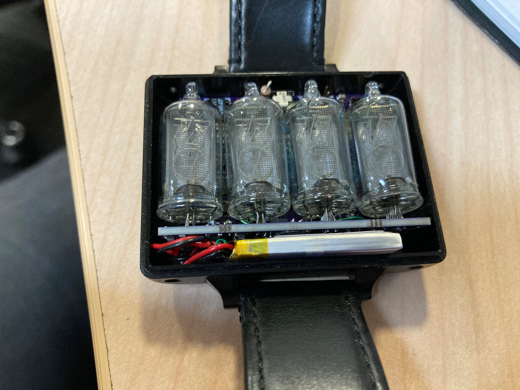
Metal Box, More Tubes, Watch Bands
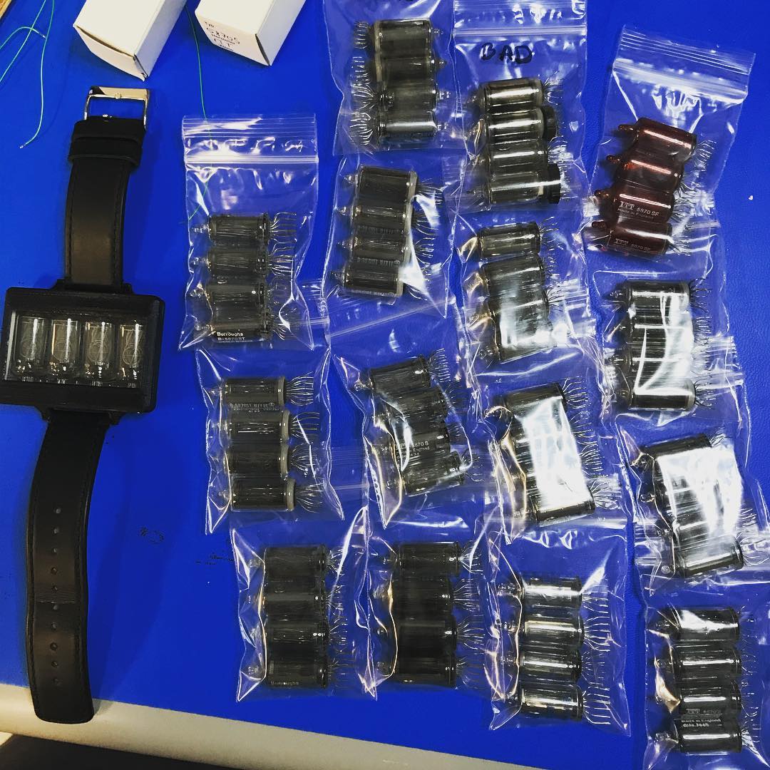
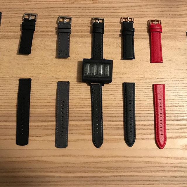
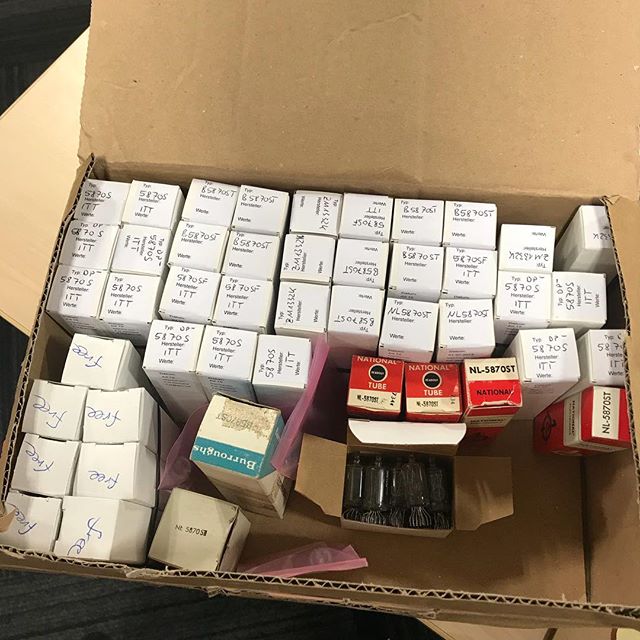
So back in late 2018 I think I looked around all over the internet for the specific tubes I'm using here. My main sources were eBay, AskJanFirst, and Sphere Research. They go for like $20-$25 per tube which gets to be expensive. I bought about 45 of them and only a few turned out to be duds. I then bought random watchbands to try out and see what fits. Settled on a black sleek one but honestly the users can replace their own. It's a standard 22mm watchband. The metal cases look amazing! I had a hell of a time gluing the glass on there with this Seiko 2 part epoxy I was referred to. For a long while the glue held but after about a year of wearing my watch almost every day it seems to have softened on the back so I'll have to figure a better solution out. One of the first things I did with the metal case is try out how water proof it is. Since I had the rubber gasket around the inner lining I was eager to see it action. You can see it in the clip below, if the crappy cell phone portrait mode isn't too distracting you'll notice maybe only a couple tiny bubbles are released as I try to submerge the box. I wouldn't advertise this watch as watertight but I can safely claim that if water spilled on the watch you wouldn't have to worry.
So back in late 2018 I think I looked around all over the internet for the specific tubes I'm using here. My main sources were eBay, AskJanFirst, and Sphere Research. They go for like $20-$25 per tube which gets to be expensive. I bought about 45 of them and only a few turned out to be duds. I then bought random watchbands to try out and see what fits. Settled on a black sleek one but honestly the users can replace their own. It's a standard 22mm watchband. The metal cases look amazing! I had a hell of a time gluing the glass on there with this Seiko 2 part epoxy I was referred to. For a long while the glue held but after about a year of wearing my watch almost every day it seems to have softened on the back so I'll have to figure a better solution out. One of the first things I did with the metal case is try out how water proof it is. Since I had the rubber gasket around the inner lining I was eager to see it action. You can see it in the clip below, if the crappy cell phone portrait mode isn't too distracting you'll notice maybe only a couple tiny bubbles are released as I try to submerge the box. I wouldn't advertise this watch as watertight but I can safely claim that if water spilled on the watch you wouldn't have to worry.
Inductive Charging
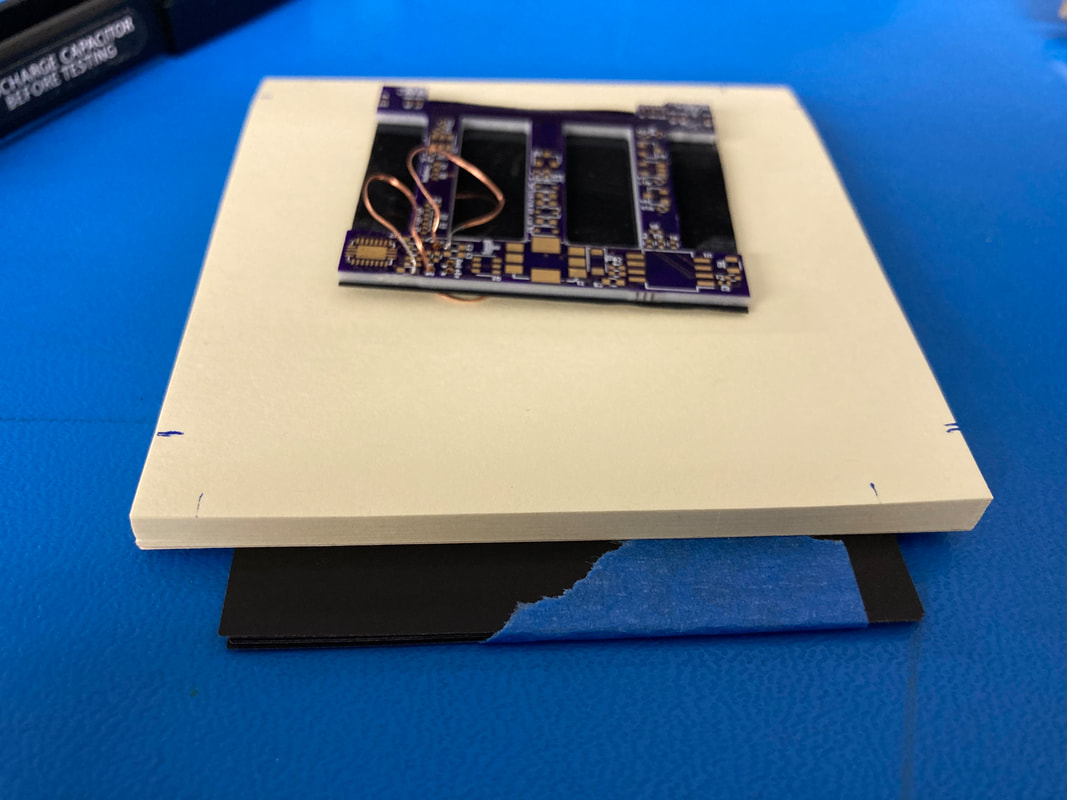
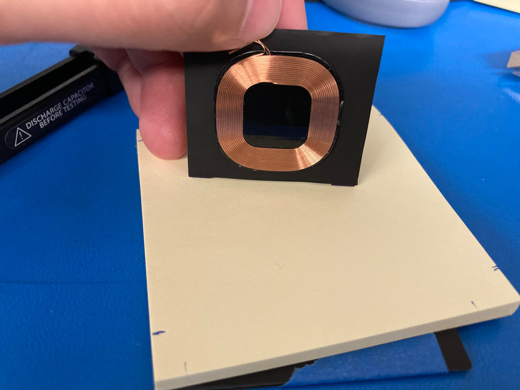
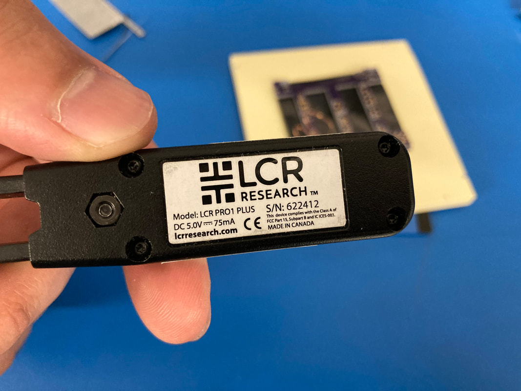
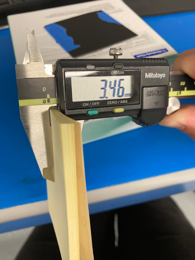
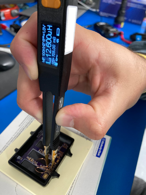
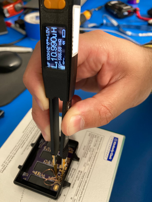
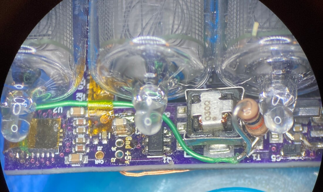
I'm ashamed to admit that my original design had a really dumb mistake in it. Every electrical engineer learns pretty early in classes that if you want to add capacitor values together you put the capacitors in parallel but the capacitors that are supposed to go in line with the receive coil were wired in series which at 120nF and 27nF give produce something like 22nF instead of the intended 147nF. Absolutely embarrassed about this but there's an easy fix. The wireless charge receive chip's datasheet tells you to measure the coil's inductance inside the final case it'll be in over a standard 3.4mm gap all over a ferrite sheet. I hadn't done that in the beginning since I was still messing with the case and had no metal housing but now that I do I can actually measure the free inductance (no ferrite sheet underneath) and in-system inductance (ferrite sheet under the 3.4mm gap) of the coil and come up with new series and parallel capacitance values for my system thanks to handy formulas the datasheet provides. Back in the day I had guessed 2nF parallel and 147nF (but accidentally 22nF) series and after measuring the inductances I'm told I need 2.3nF parallel and 200nF series. Honestly I don't know how the charging has worked all this time these chips and the Qi standard is amazing at magnetically coupling the coils. I'll be ordering replacement caps to fix this issue manually on all the production boards.
I'm ashamed to admit that my original design had a really dumb mistake in it. Every electrical engineer learns pretty early in classes that if you want to add capacitor values together you put the capacitors in parallel but the capacitors that are supposed to go in line with the receive coil were wired in series which at 120nF and 27nF give produce something like 22nF instead of the intended 147nF. Absolutely embarrassed about this but there's an easy fix. The wireless charge receive chip's datasheet tells you to measure the coil's inductance inside the final case it'll be in over a standard 3.4mm gap all over a ferrite sheet. I hadn't done that in the beginning since I was still messing with the case and had no metal housing but now that I do I can actually measure the free inductance (no ferrite sheet underneath) and in-system inductance (ferrite sheet under the 3.4mm gap) of the coil and come up with new series and parallel capacitance values for my system thanks to handy formulas the datasheet provides. Back in the day I had guessed 2nF parallel and 147nF (but accidentally 22nF) series and after measuring the inductances I'm told I need 2.3nF parallel and 200nF series. Honestly I don't know how the charging has worked all this time these chips and the Qi standard is amazing at magnetically coupling the coils. I'll be ordering replacement caps to fix this issue manually on all the production boards.
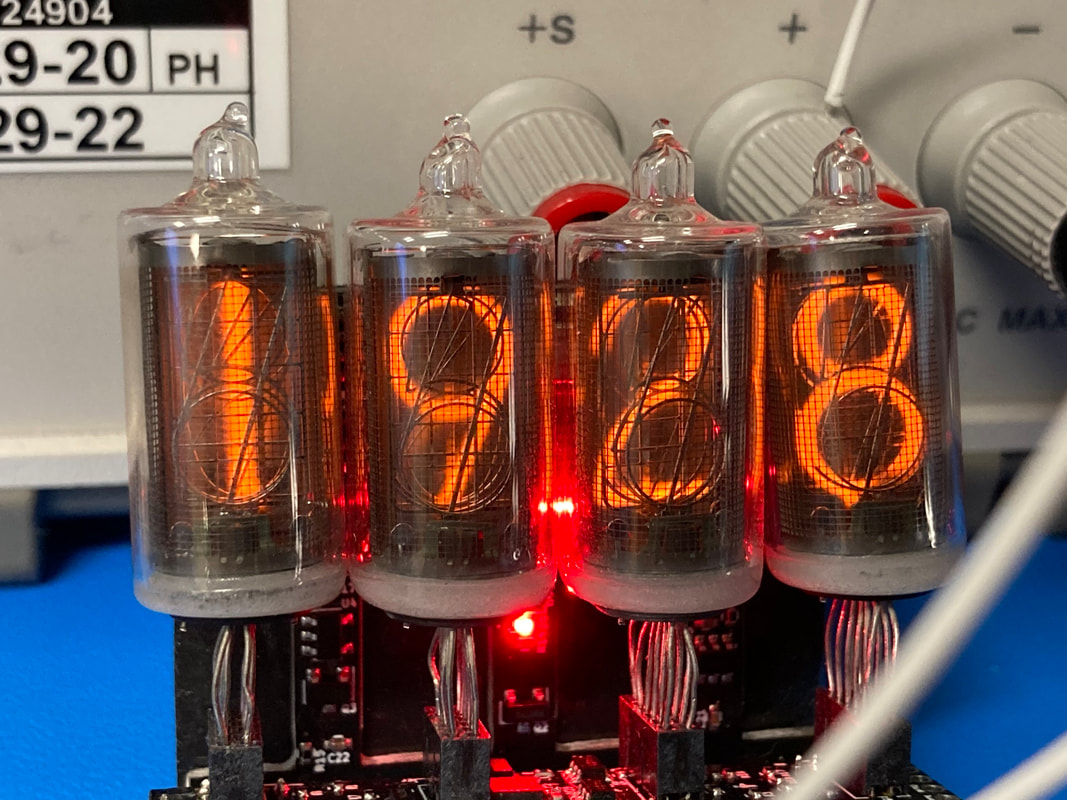
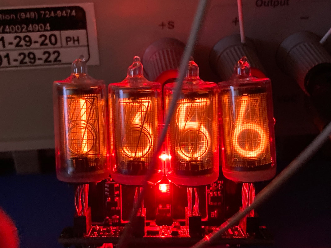
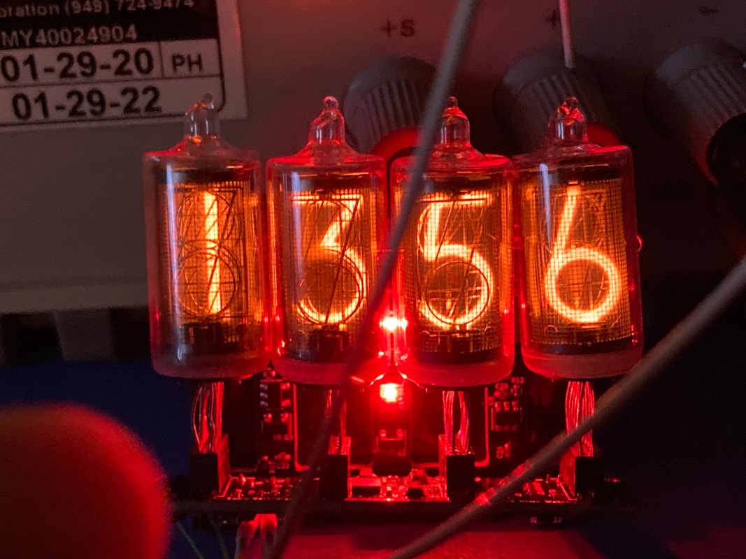
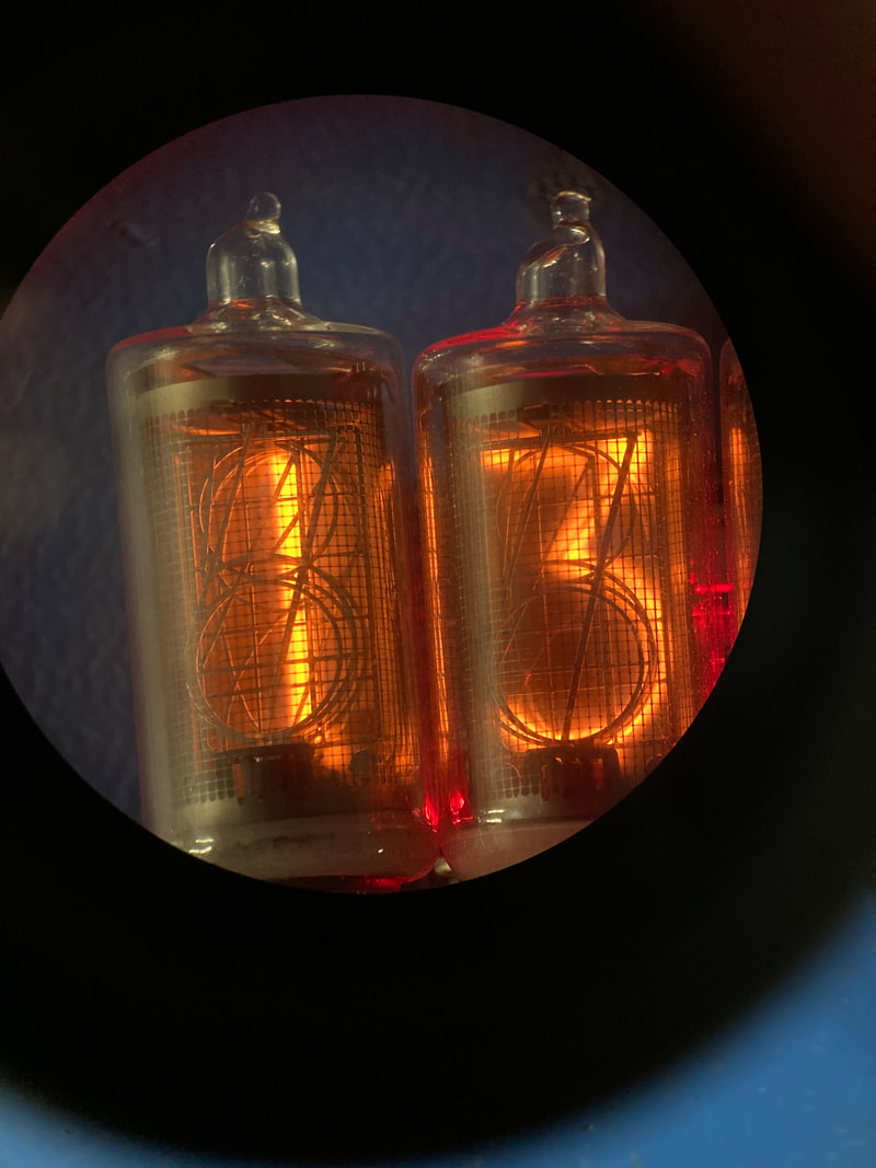
Ghostbusters
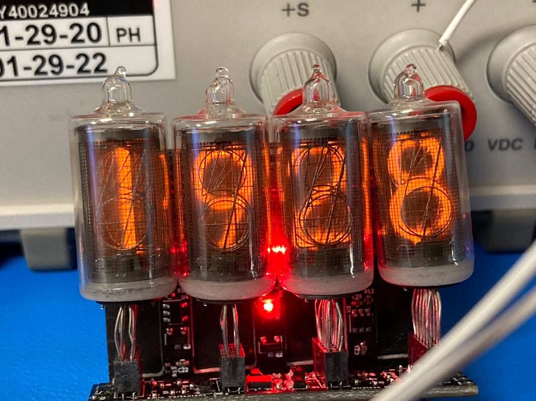
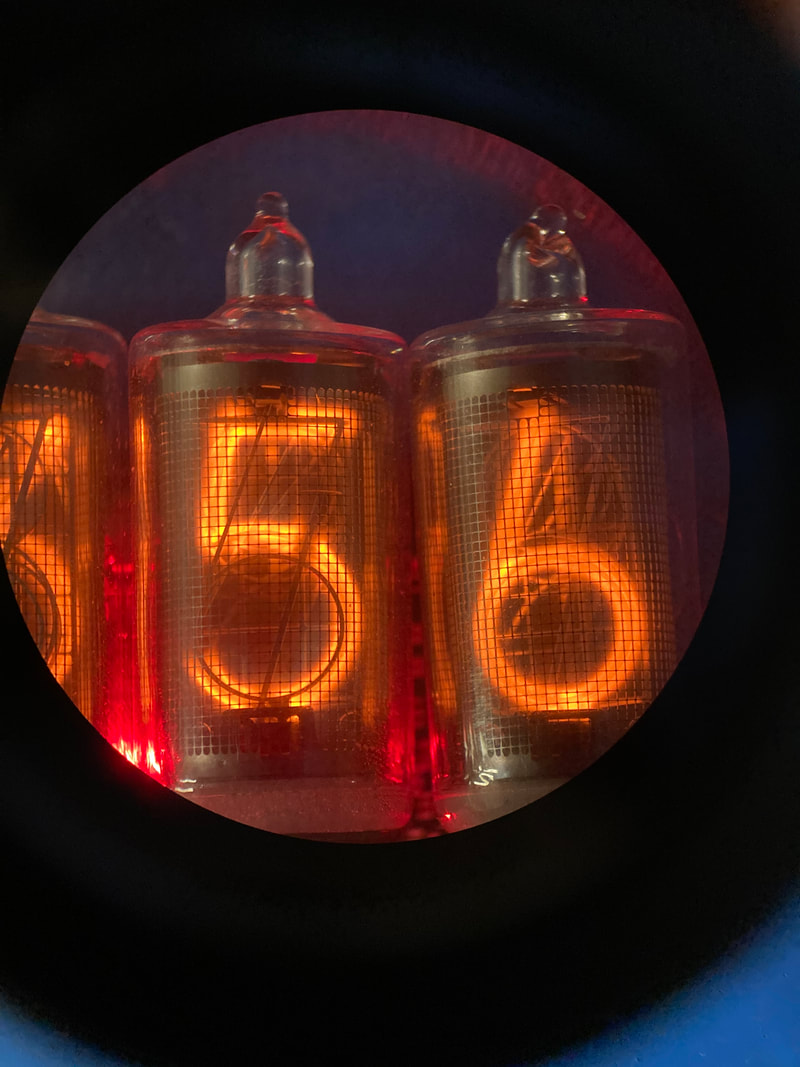
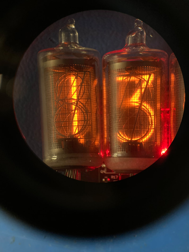
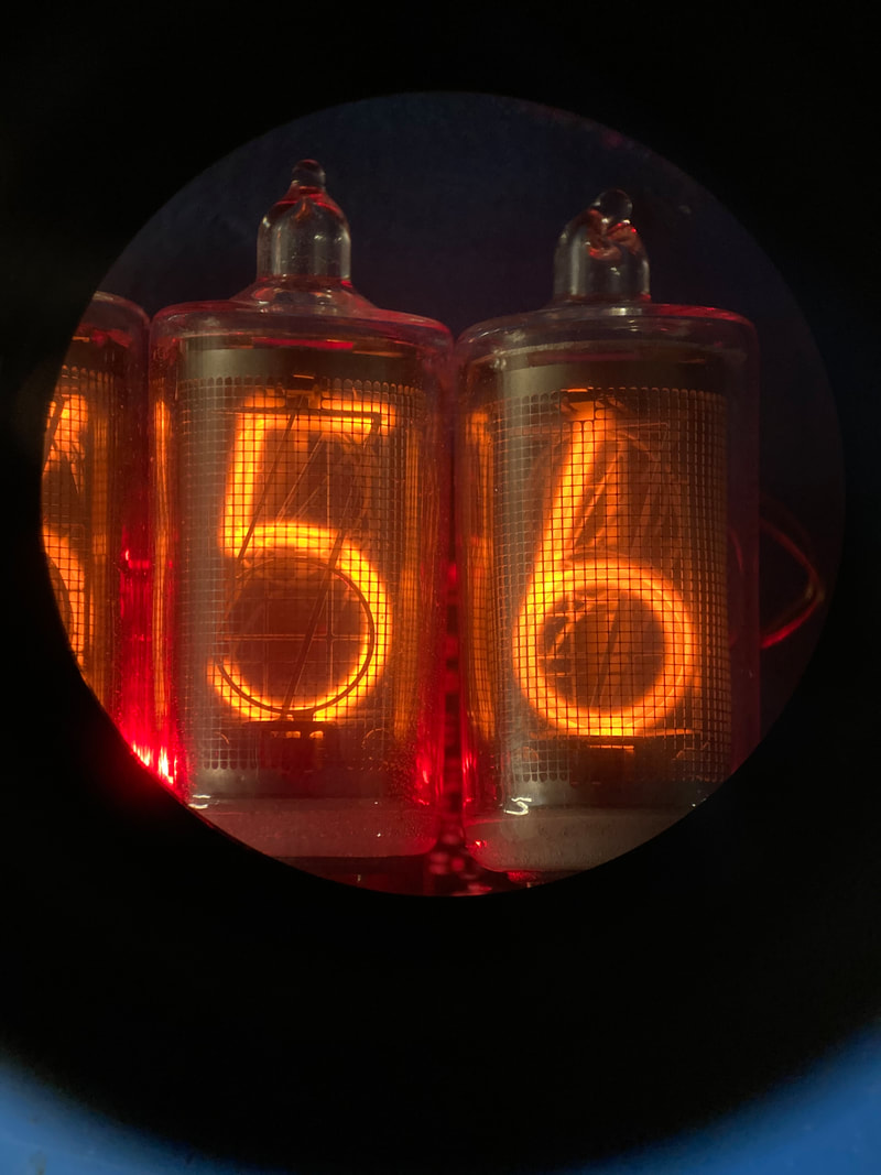
In my last post I talked about the ghosting effect where one tube's lit number will cause the same number to glow on another tube. I had a hunch for what's happening which was related to the fact that i'm using this matrixed approach of lighting each tube (10 cathodes, 4 tubes, like row/column). Anyway, my fix was diode ORing the 10 cathodes to a single 51v zener. The idea is that if the lit numeral in tube 1, for example, is sputtering electrons onto its neighboring numeral then that numeral's voltage will never go above 51v and therefore never actually enable another tube's numeral to be ghostly glowing since 51v is way below the 180v starting or 120v maintaining voltage. Well it definitely worked as you can see below. The new zenered design has no ghosting going on whereas the non-zenered design you can still see the ghosts. The problem that I can sorta perceive now is that the zenered display isn't as sharp as the non-zenered display. I'll have to make a couple watches and do real comparison since the camera doesn't do it justice but I think all the numerals being held at 51v while a single numeral glows brightly is sorta fuzzy-ing out the whole tube slightly. It's like the other cathodes can't be too low in voltage or else they will glow due to the 120v at the intended cathode, but they can't all be too high voltage either because then there is a sneak path for current to light up another tube. Not sure, not a big problem. The Zener diode is in an easily accessible spot and I can change the value, take it out, or leave it be. Will play around with a higher zener voltage... not sure.
In my last post I talked about the ghosting effect where one tube's lit number will cause the same number to glow on another tube. I had a hunch for what's happening which was related to the fact that i'm using this matrixed approach of lighting each tube (10 cathodes, 4 tubes, like row/column). Anyway, my fix was diode ORing the 10 cathodes to a single 51v zener. The idea is that if the lit numeral in tube 1, for example, is sputtering electrons onto its neighboring numeral then that numeral's voltage will never go above 51v and therefore never actually enable another tube's numeral to be ghostly glowing since 51v is way below the 180v starting or 120v maintaining voltage. Well it definitely worked as you can see below. The new zenered design has no ghosting going on whereas the non-zenered design you can still see the ghosts. The problem that I can sorta perceive now is that the zenered display isn't as sharp as the non-zenered display. I'll have to make a couple watches and do real comparison since the camera doesn't do it justice but I think all the numerals being held at 51v while a single numeral glows brightly is sorta fuzzy-ing out the whole tube slightly. It's like the other cathodes can't be too low in voltage or else they will glow due to the 120v at the intended cathode, but they can't all be too high voltage either because then there is a sneak path for current to light up another tube. Not sure, not a big problem. The Zener diode is in an easily accessible spot and I can change the value, take it out, or leave it be. Will play around with a higher zener voltage... not sure.
Battery
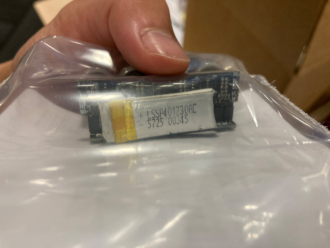
The biggest problem I have no is the battery sitting inside. I've had some bad luck with the tiny battery board I made to because all the forces of installing and uninstalling the battery is going thru those battery tabs which were fickle anyway. I experimented with having the original wires that come with the battery be connectorize and coil up and fit into the cavity. Results were great for fitting it all in but for some reason the battery keeps disconnecting momentarily from the header so I'll have to beef that up somehow. I ordered a bunch of these batteries from some Chinese ebay shop. Apparently this specific battery (401230) is hot with bluetooth headsets. I think the part number is related to the size of the cells (40mm length, 12cm width, 3.0 mm thick) but I'm not sure. It definitely made finding this battery from other sellers easier though since my first batch was from Tenergy who stopped caring about this cell. I also confirmed that when the battery is correctly seated and the whole thing is in the metal case that the charger indeed does its ~50mA "half-C" charging. More to come on this front as I experiment with securing the battery connection. I also measured some voltages and ADC counts on the battery but want to make that more robust. Will have to ask my coworkers who work with batteries more how to characterize these cells so I can pick 100% and 0% state of charge in a smart way.
The biggest problem I have no is the battery sitting inside. I've had some bad luck with the tiny battery board I made to because all the forces of installing and uninstalling the battery is going thru those battery tabs which were fickle anyway. I experimented with having the original wires that come with the battery be connectorize and coil up and fit into the cavity. Results were great for fitting it all in but for some reason the battery keeps disconnecting momentarily from the header so I'll have to beef that up somehow. I ordered a bunch of these batteries from some Chinese ebay shop. Apparently this specific battery (401230) is hot with bluetooth headsets. I think the part number is related to the size of the cells (40mm length, 12cm width, 3.0 mm thick) but I'm not sure. It definitely made finding this battery from other sellers easier though since my first batch was from Tenergy who stopped caring about this cell. I also confirmed that when the battery is correctly seated and the whole thing is in the metal case that the charger indeed does its ~50mA "half-C" charging. More to come on this front as I experiment with securing the battery connection. I also measured some voltages and ADC counts on the battery but want to make that more robust. Will have to ask my coworkers who work with batteries more how to characterize these cells so I can pick 100% and 0% state of charge in a smart way.
Next Steps
So in general I'm super happy with the last couple weeks. I was originally saddened by the boards that came back from Shenzen because the wireless charging didn't work. When I came back to the project I realized that the board house had not reflowed the wireless charging chip's ground pad underneath the part. A bit of reflowing later and we were in business so I'm happy to see my design isn't crap (apart from the dumb capacitor mistake). Throughout the 18 months I've been away I had my SN00 watch's numeral "2" on the right-most tube die which made the whole tube glow angrily when I lit it so I had to cut that leg off so I'm limping a little unless I choose to switch the tube but I worry about the plated thru holes there, I've beat this board up a lot. I suspect the numeral died because these are the tubes I've worked with for development plus for some time I accidently didn't have the regulator turn down to 120v once current started flowing so these poor numbers have been screaming at 180v for months (make sure the pair or resistors you laid out next to each other have clear silkscreen showing if the parts are going on horizontally or vertically). All in all I'm exciting to round out this project and start shipping the preordered watches. If those go well and there is ample demand then maybe I do a second run? I have a ton of ideas on improvements which would be great to try out. See you guys later.
So in general I'm super happy with the last couple weeks. I was originally saddened by the boards that came back from Shenzen because the wireless charging didn't work. When I came back to the project I realized that the board house had not reflowed the wireless charging chip's ground pad underneath the part. A bit of reflowing later and we were in business so I'm happy to see my design isn't crap (apart from the dumb capacitor mistake). Throughout the 18 months I've been away I had my SN00 watch's numeral "2" on the right-most tube die which made the whole tube glow angrily when I lit it so I had to cut that leg off so I'm limping a little unless I choose to switch the tube but I worry about the plated thru holes there, I've beat this board up a lot. I suspect the numeral died because these are the tubes I've worked with for development plus for some time I accidently didn't have the regulator turn down to 120v once current started flowing so these poor numbers have been screaming at 180v for months (make sure the pair or resistors you laid out next to each other have clear silkscreen showing if the parts are going on horizontally or vertically). All in all I'm exciting to round out this project and start shipping the preordered watches. If those go well and there is ample demand then maybe I do a second run? I have a ton of ideas on improvements which would be great to try out. See you guys later.
War zone of reworks on SN00
