Assembly
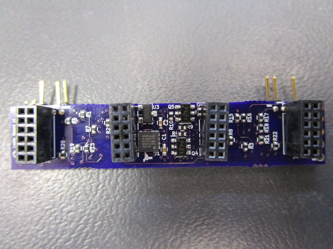
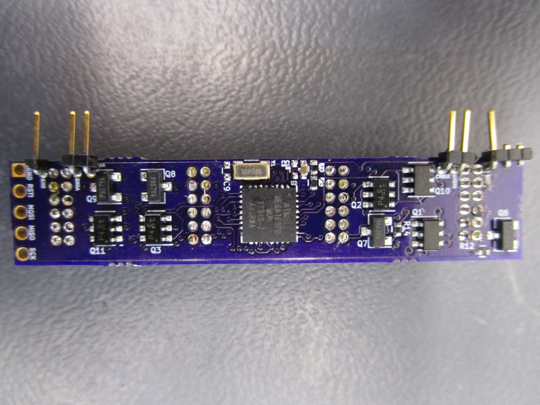
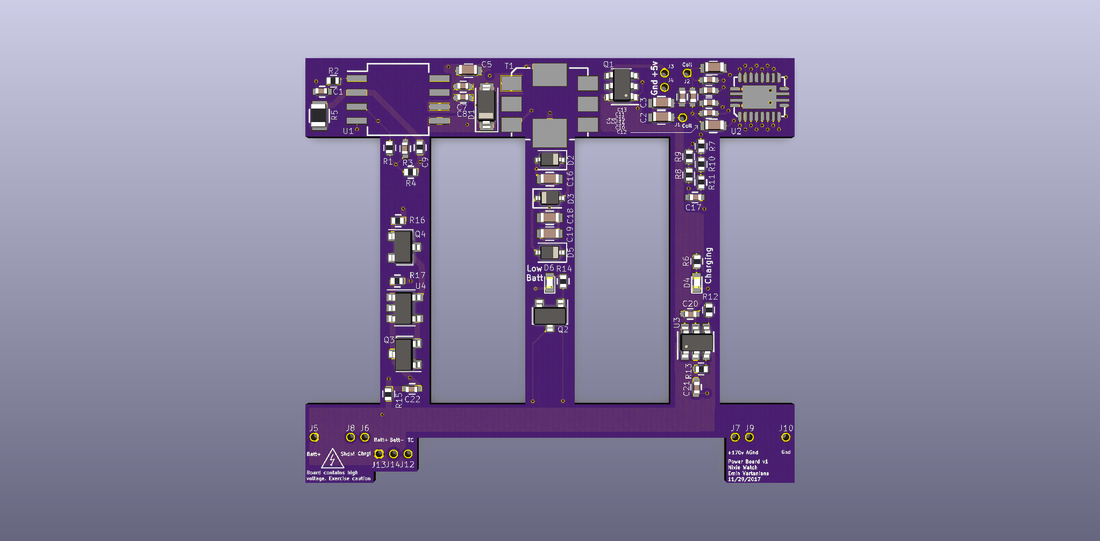
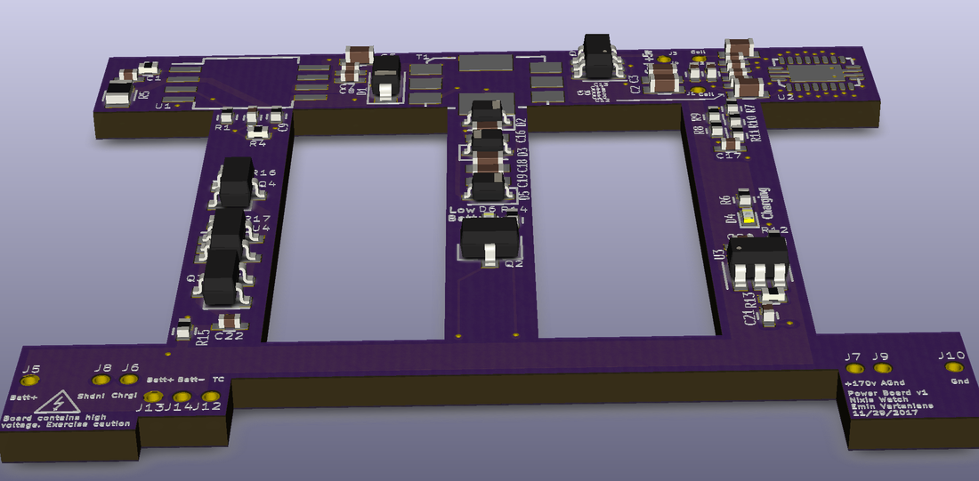
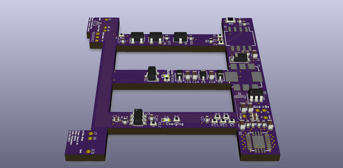
The power board came in and I assembled all the components and did a fit check. Found some errors here and there, SOT23 footprints were messed up just like in the logic board, some missing pulldowns, etc. All in all it fits in the case pretty well! attached wires to the part where the logic board would talk and wiggled the SHDN! and CHRG! signals which worked great. the high voltage supply creates 180v just fine, the 5v auxiliary power path is all good, battery charges correctly, LED's look great as well. Really impressed by it all.
The power board came in and I assembled all the components and did a fit check. Found some errors here and there, SOT23 footprints were messed up just like in the logic board, some missing pulldowns, etc. All in all it fits in the case pretty well! attached wires to the part where the logic board would talk and wiggled the SHDN! and CHRG! signals which worked great. the high voltage supply creates 180v just fine, the 5v auxiliary power path is all good, battery charges correctly, LED's look great as well. Really impressed by it all.
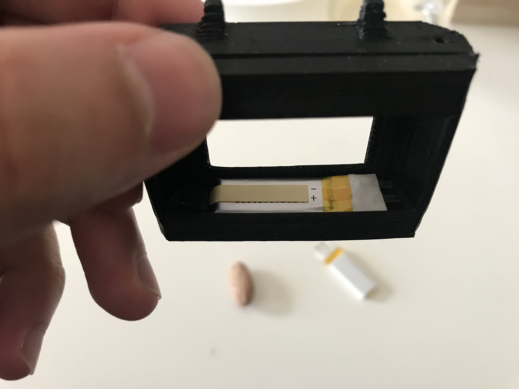
 The whole power section in the top there | 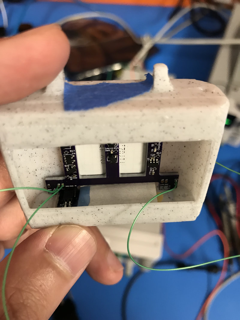 You can see the battery plugged into the power board | 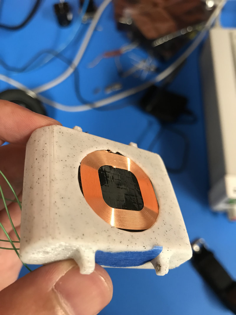 Coil for receiving power peeking through the window |
Battery
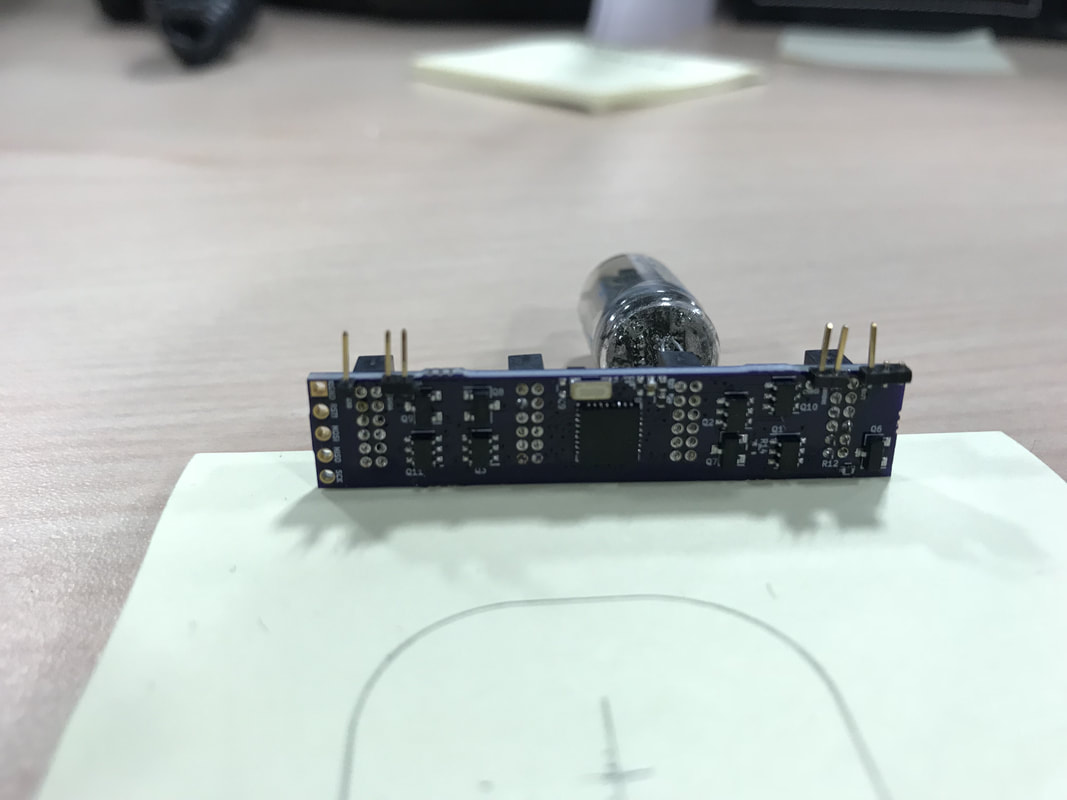
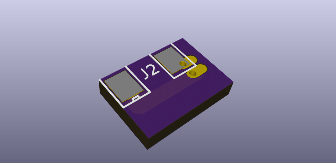
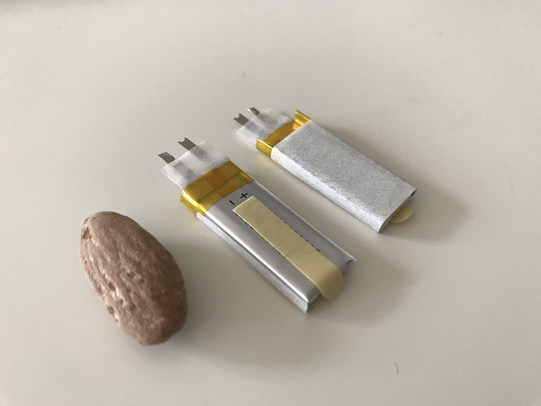
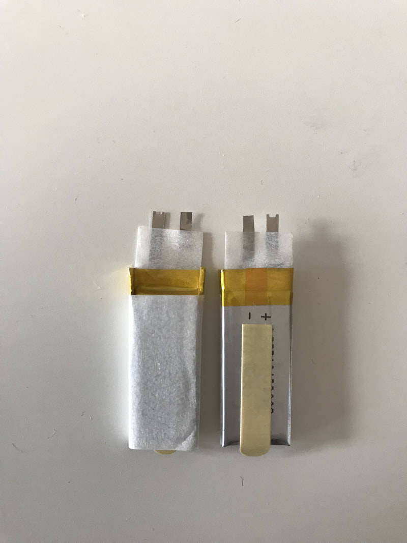
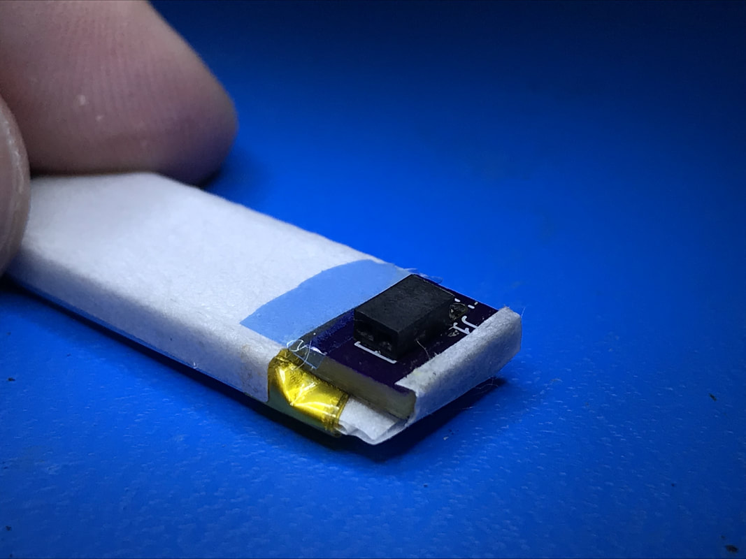
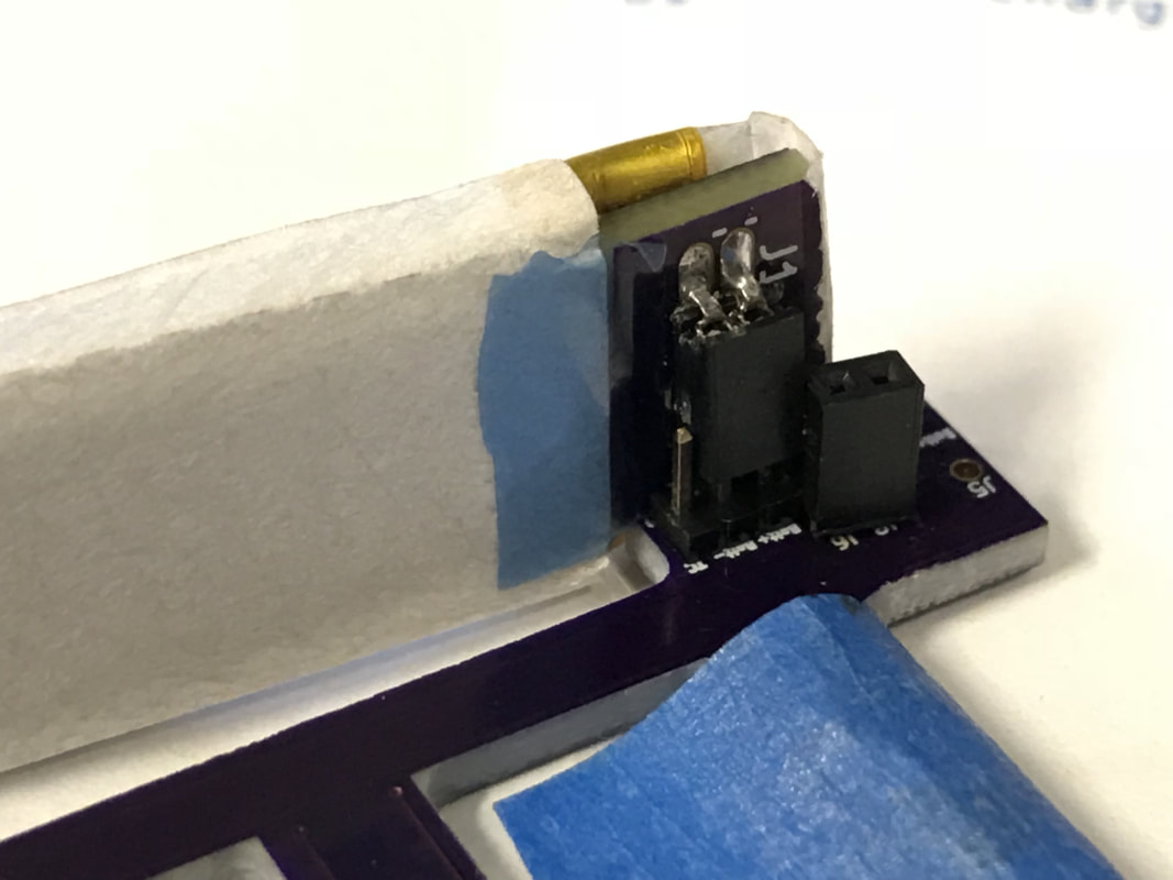
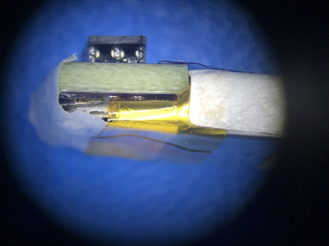
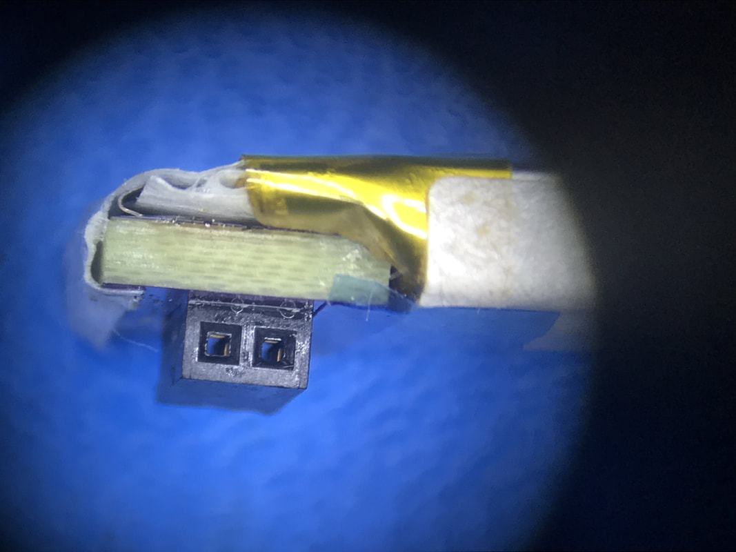
Since the battery interface is tabs it makes it hard to have an easy way to plug and uplug the thing from the rest of the system. So the tiny battery board I built basically turns the vertically stacks tabs of the battery 90deg down so I can plug it into the power PCB through headers. This helps in testing and general service. The tabs solder to pads on the underside of the board and the lines are routed to a female header (not male so its not exposed). Will eventually do a better job of taping everything up but I think it looks pretty good.
Since the battery interface is tabs it makes it hard to have an easy way to plug and uplug the thing from the rest of the system. So the tiny battery board I built basically turns the vertically stacks tabs of the battery 90deg down so I can plug it into the power PCB through headers. This helps in testing and general service. The tabs solder to pads on the underside of the board and the lines are routed to a female header (not male so its not exposed). Will eventually do a better job of taping everything up but I think it looks pretty good.
 |  |  |  |
Wireless Charging
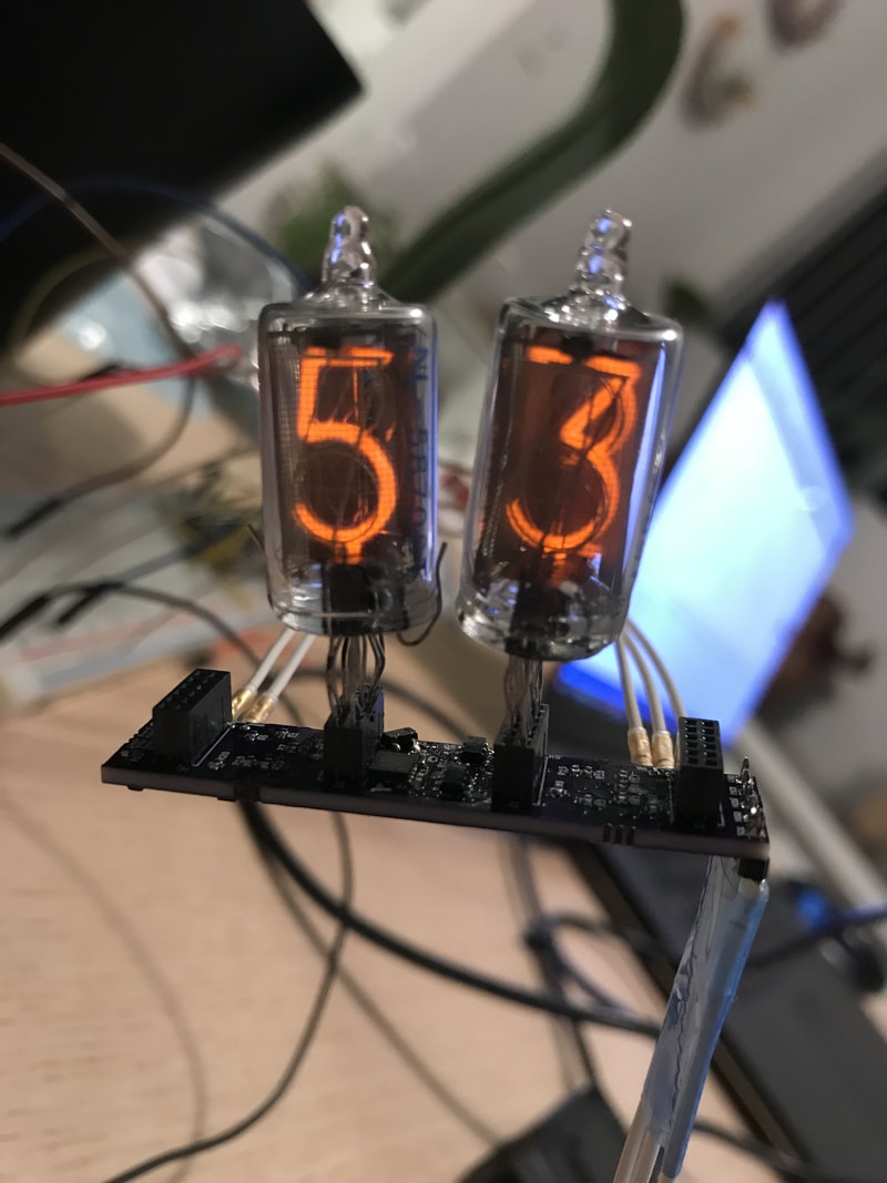
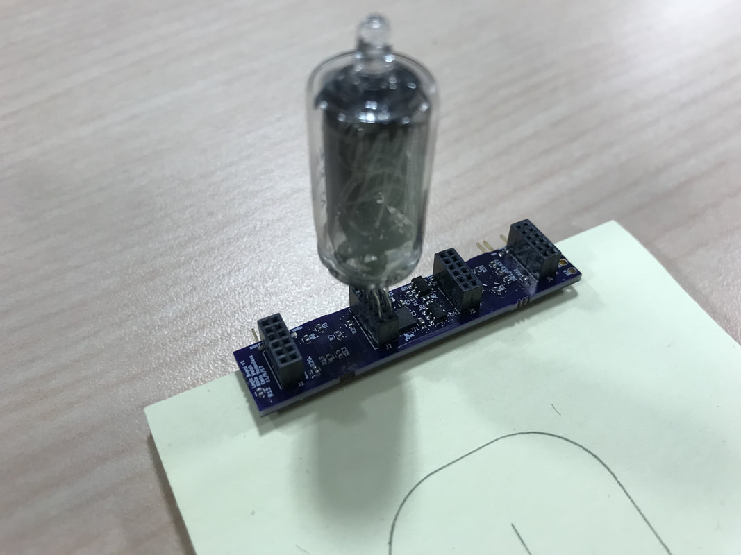
This was the big scary part of the power board since its super analog and I have less insight into it but for the most part it went smoothly. I went up in baby steps first just the coil then taping it to the back of the pcb then really soldered on and so on. I was afraid the capacitance values I calculated for the input of the coil would be not good enough on the count of I never measured the inductances as TI prescribes on their datasheet. I took the table in their datasheet that lists the free inductance and the coupled inductances of some known and recommended coils and saw that the ratio between the two L's were sorta constant across the line, so I just went with that and it seems to have worked for the best even though this wasn't one of the recommended coils. I found out the 5v input has to be tied down very loosely since every time the charging starts there's some bounce internal to the TI chip and it thinks the 5v input is plugged in so it shuts off wireless charging, very annoying. I also found out the TS/CTRL line I left floating on the part should have been tied down by a 10k otherwise the whole thing doesn't even start. Otherwise it works great! I even tried the pcb surrounded by a frame of aluminum since that could mess with the coupling but nope, worked beautifully. Watched the whole system wirelessly charge the battery up to the correct voltage then stop the charger and the light turns off, its amazing! While it was running the wireless received and the charger chip get kinda hot. so U2 gets to like 60C, U3 around 50C, the coil gets to like 30C, and the lab I was in was around 20C. I was happy to find the aluminum frame didn't get hot at all, and the battery remained at a low 25C or so. This is charging the battery at ~55mA. Great success!
This was the big scary part of the power board since its super analog and I have less insight into it but for the most part it went smoothly. I went up in baby steps first just the coil then taping it to the back of the pcb then really soldered on and so on. I was afraid the capacitance values I calculated for the input of the coil would be not good enough on the count of I never measured the inductances as TI prescribes on their datasheet. I took the table in their datasheet that lists the free inductance and the coupled inductances of some known and recommended coils and saw that the ratio between the two L's were sorta constant across the line, so I just went with that and it seems to have worked for the best even though this wasn't one of the recommended coils. I found out the 5v input has to be tied down very loosely since every time the charging starts there's some bounce internal to the TI chip and it thinks the 5v input is plugged in so it shuts off wireless charging, very annoying. I also found out the TS/CTRL line I left floating on the part should have been tied down by a 10k otherwise the whole thing doesn't even start. Otherwise it works great! I even tried the pcb surrounded by a frame of aluminum since that could mess with the coupling but nope, worked beautifully. Watched the whole system wirelessly charge the battery up to the correct voltage then stop the charger and the light turns off, its amazing! While it was running the wireless received and the charger chip get kinda hot. so U2 gets to like 60C, U3 around 50C, the coil gets to like 30C, and the lab I was in was around 20C. I was happy to find the aluminum frame didn't get hot at all, and the battery remained at a low 25C or so. This is charging the battery at ~55mA. Great success!
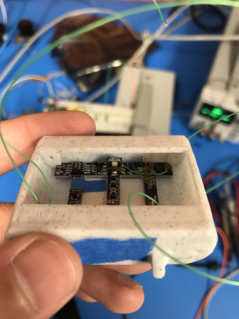
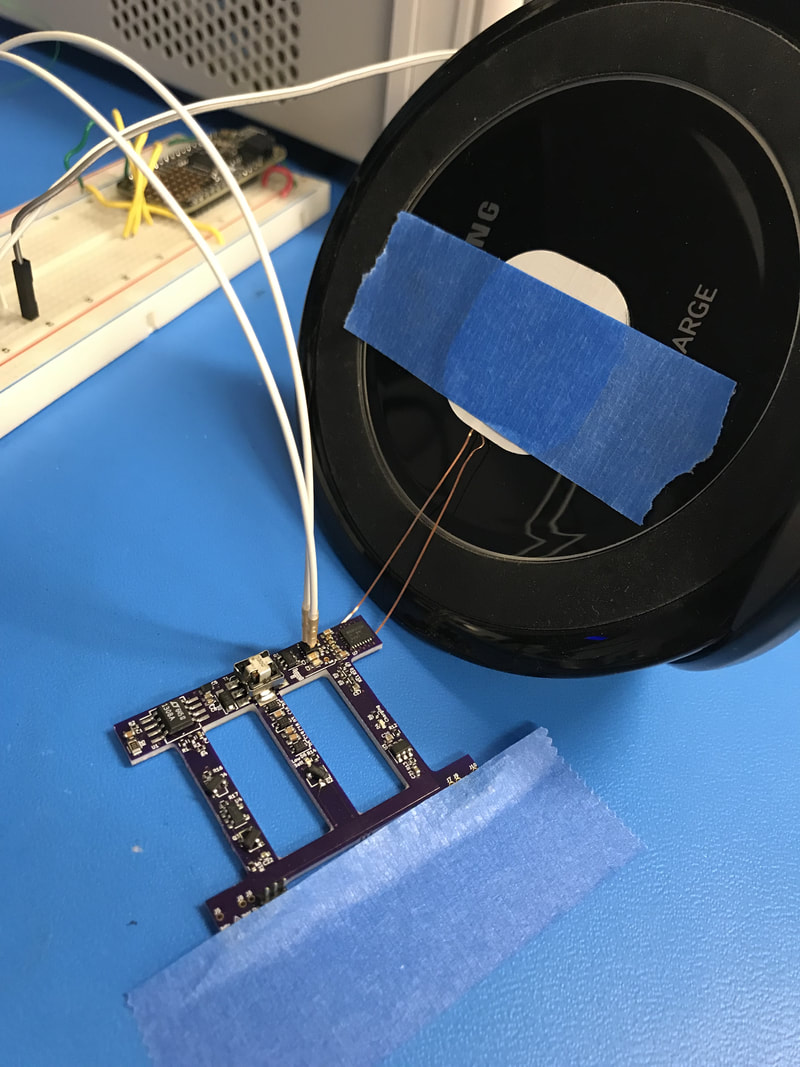 Baby steps: only the coil on the charger so I get no extra variables coupling in. | 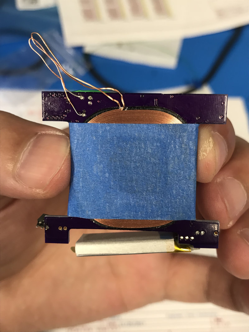 Close to how the final thing will look like, just bent the extra wire length away for test | 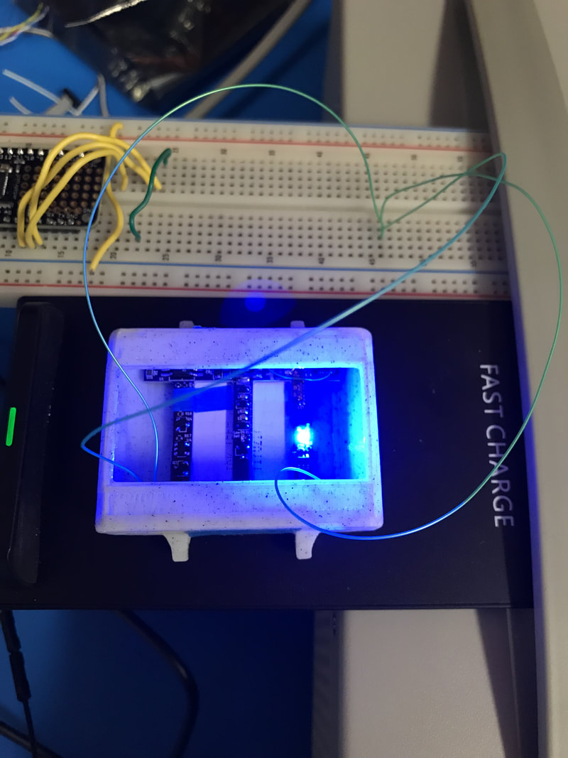 Coil and PCB in the 3D printed case charging (blue LED). The wires coming out are control lines the microprocessor would control once installed | 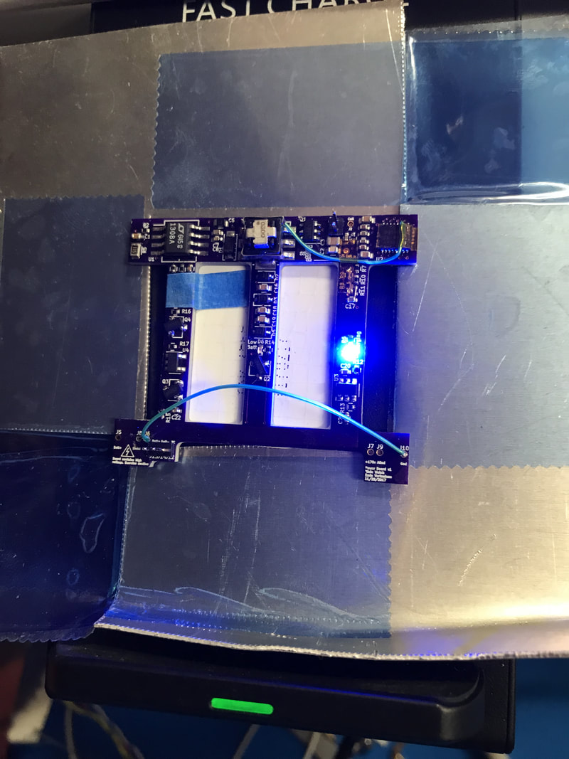 Metal in the field could interfere and stop the charging process and since the case is going to be aluminum I tested with this frame to make sure it still charges. It does! |
Transformer Study
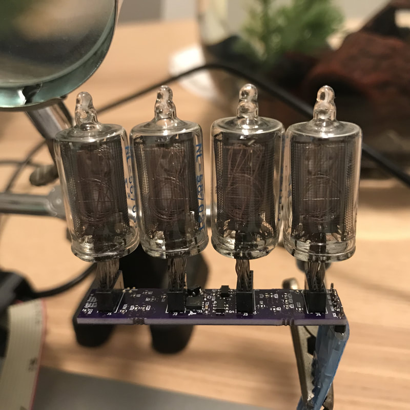
Did a quick transformer study to make sure I was choosing the right transformer ratio. It seems that even though the SPICE simulations showed the lower ratios should be more efficient I saw a slightly worse performance at 1:20 with the 1:30 and 1:40 being pretty much same thing. This test was doing the same routine as my last post which displayed the angle of the PCB on 3 tubes. Vin = 4v, 1ms of tube on time, 2ms off time, 26ms between each triplet.
Did a quick transformer study to make sure I was choosing the right transformer ratio. It seems that even though the SPICE simulations showed the lower ratios should be more efficient I saw a slightly worse performance at 1:20 with the 1:30 and 1:40 being pretty much same thing. This test was doing the same routine as my last post which displayed the angle of the PCB on 3 tubes. Vin = 4v, 1ms of tube on time, 2ms off time, 26ms between each triplet.
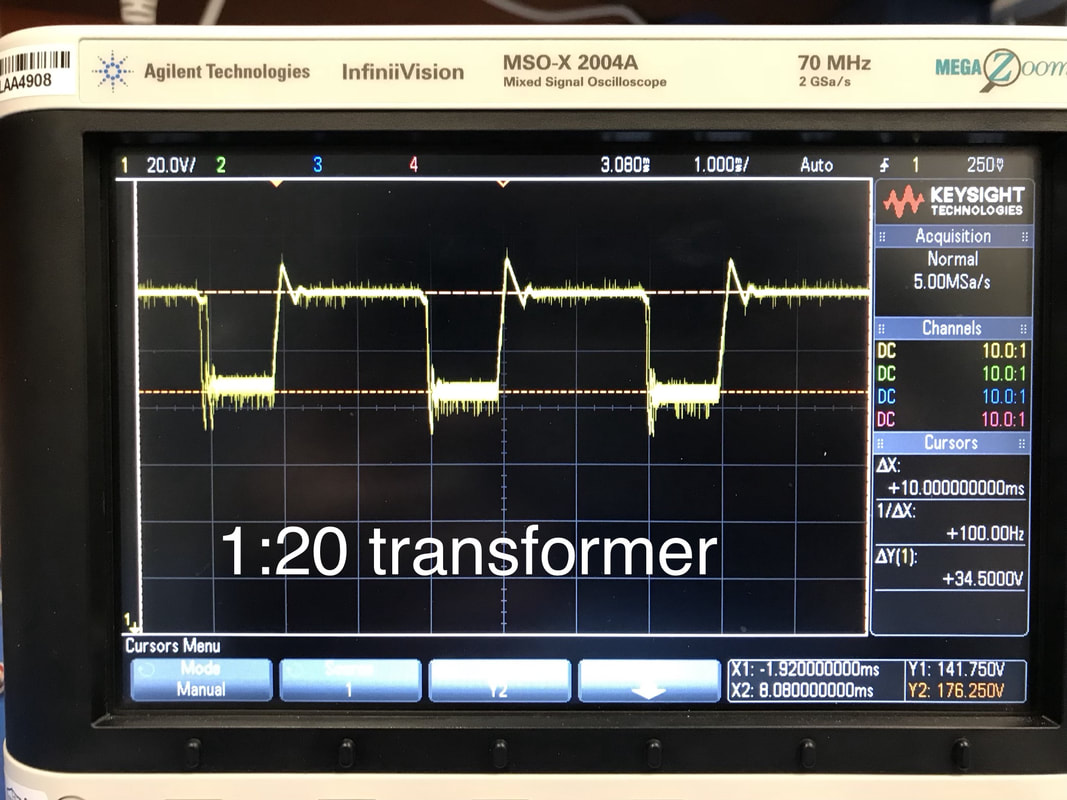 No load: 23mA, Loaded: 42mA | 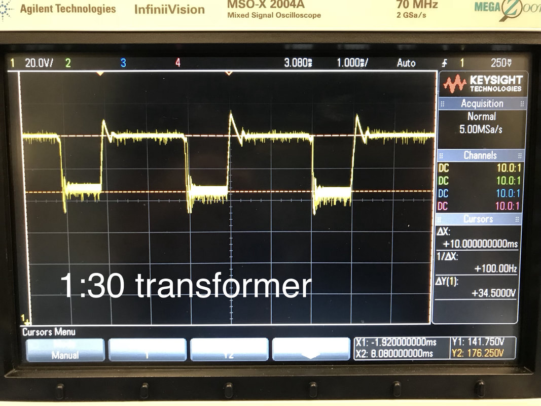 No Load: 19mA, Loaded: 36mA | 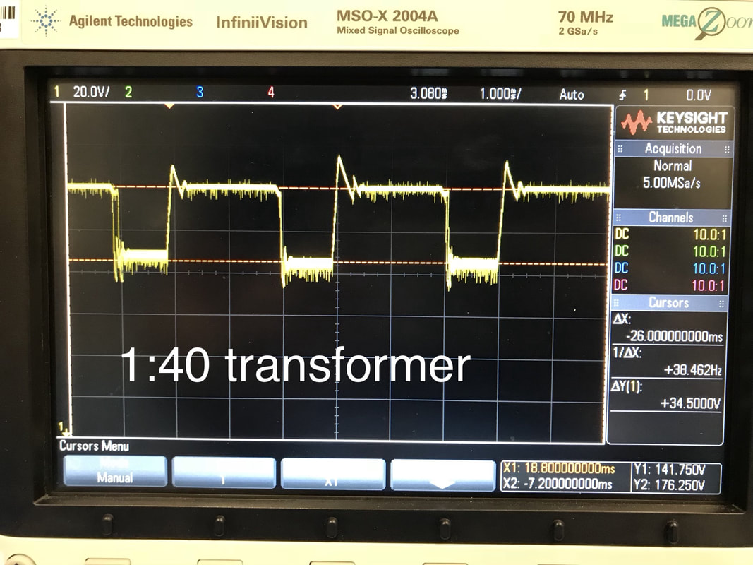 No Load: 19mA, Loaded: 37mA |
Next Steps and My Idiocy
On the logic board front I added on the 4th tube and made sure I could talk to it. Beginning to be confident, I reprogrammed the efuses to switch the clock source from the internal 8Mhz RC to the external real time crystal (32.768Khz) so code would get more realistic. Then the whole thing wouldn't talked to me anymore. After some digging I found out the programmer pod I was using (Adafruit's USBtiny) doesn't talk slowly enough. For AVR's the programmer communication bit rate has to be at most 1/4 of the chip's system clock. Well I'm at ~32khz, had the DIV8 fuse active so 4Khz, and a quarter of that means the pod is talked 1kbit/s. The USBtiny can only go down to about 4kbits/s. After a bit of research I went with Atmel's old AVRISP MKII pod as a replacement. I found it on ebay for ~$20. Atmel (microchip now) has stopped making them so I had to get some Chinese imitation one, hope it works.The MKII goes down to 50hz if need be so we're all good.
Until the new programmer pod comes I'll be working on some current/power measurements of the power board and making sure the battery charging and discharging protection circuitry works well enough for prime time. Also gotta power a nixie with the power board converter so I know it's got enough input capacitance and all.