Her're s a couple pretty pictures under the microscope at the beginning since this post is a bit word heavy.
 |  |
Time slip
Since the last post I've been doing measurements of how good the watch is keeping time and it seems to be losing about 2 seconds every hour which is horrible! This corresponds to about 200ppm which is way out of bed with the crystal's 20ppm tolerance. After a ton of digging I found the most probable culprit to be capacitance. Crystals have a specified load capacitance, sort of a measure of how heavy the crystal seems electrically as the microcontroller is vibrating it. What you're supposed to do is match the capacitance of the crystal with external capacitors hanging off each terminal of the crystal to ground. That external cap capacitance along with any other capacitance internal to the micro or the board should add up to the same capacitance as the crystal so that it "feels" weightless. Well the ATMEGA168pb's XTAL pins have a capacitance of 18pF and 8pF (so not matched... makes it harder to balance) and the biggest capacitance I can find withing the max ESR limit is 9pF crystal. With the formula Atmel shows on their datasheet I'd have to employ negative capacitances to match the tiny crystal's load. I originally had a 3pF crystal on there but I bought a 9pF one and installed it. Will measure the time slip there and see what games I can play. I'm shooting for <10ppm which is 1 minutes every month which aint too bad.
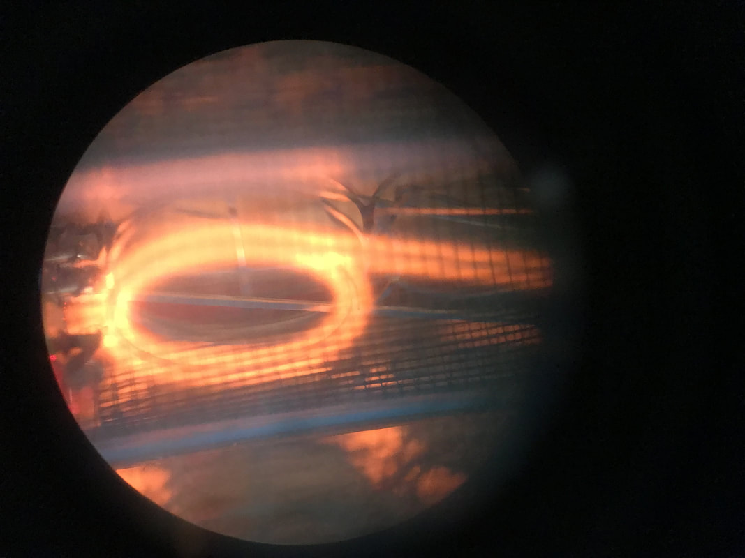
I also realized I should try and do away with the crystal BS and go straight to an osacillator. They can be more stable and drive capacitive loads just fine. Found the "SIT1552AI-JE-DCC-32.768E" from SiTime on Digikey which is a TCXO (temperature compensated crystal oscillator) so it takes into account variations in temp so I don't slow down or speed up when the watch is under the hot sun. The oscillator draws about 1uA steadily which I think I have the budget for. You can see my poor attempt at soldering it on. After breaking one of the solderballs I decided to see how the 9pF crystal is doing and if it was still really bad I'll spin a tiny breakout board for this oscillator to test it out.
Look at these sources for reference on this matter:
AVR MicroController Hardware Design Considerations
Choosing the Right Crystal and Caps for your Design
Pierce-Gate Crystal Oscillator Introduction
Another Pierce-Gate Oscillator Paper
Quartz Crystal Design Notes
Since the last post I've been doing measurements of how good the watch is keeping time and it seems to be losing about 2 seconds every hour which is horrible! This corresponds to about 200ppm which is way out of bed with the crystal's 20ppm tolerance. After a ton of digging I found the most probable culprit to be capacitance. Crystals have a specified load capacitance, sort of a measure of how heavy the crystal seems electrically as the microcontroller is vibrating it. What you're supposed to do is match the capacitance of the crystal with external capacitors hanging off each terminal of the crystal to ground. That external cap capacitance along with any other capacitance internal to the micro or the board should add up to the same capacitance as the crystal so that it "feels" weightless. Well the ATMEGA168pb's XTAL pins have a capacitance of 18pF and 8pF (so not matched... makes it harder to balance) and the biggest capacitance I can find withing the max ESR limit is 9pF crystal. With the formula Atmel shows on their datasheet I'd have to employ negative capacitances to match the tiny crystal's load. I originally had a 3pF crystal on there but I bought a 9pF one and installed it. Will measure the time slip there and see what games I can play. I'm shooting for <10ppm which is 1 minutes every month which aint too bad.
I also realized I should try and do away with the crystal BS and go straight to an osacillator. They can be more stable and drive capacitive loads just fine. Found the "SIT1552AI-JE-DCC-32.768E" from SiTime on Digikey which is a TCXO (temperature compensated crystal oscillator) so it takes into account variations in temp so I don't slow down or speed up when the watch is under the hot sun. The oscillator draws about 1uA steadily which I think I have the budget for. You can see my poor attempt at soldering it on. After breaking one of the solderballs I decided to see how the 9pF crystal is doing and if it was still really bad I'll spin a tiny breakout board for this oscillator to test it out.
Look at these sources for reference on this matter:
AVR MicroController Hardware Design Considerations
Choosing the Right Crystal and Caps for your Design
Pierce-Gate Crystal Oscillator Introduction
Another Pierce-Gate Oscillator Paper
Quartz Crystal Design Notes
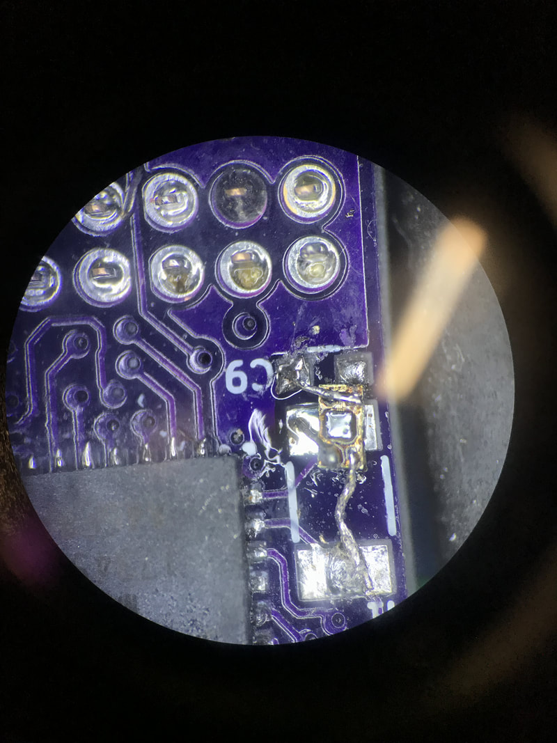 Trying to solder the tiny TCXO in place. Sad Attempt as it didn't work | 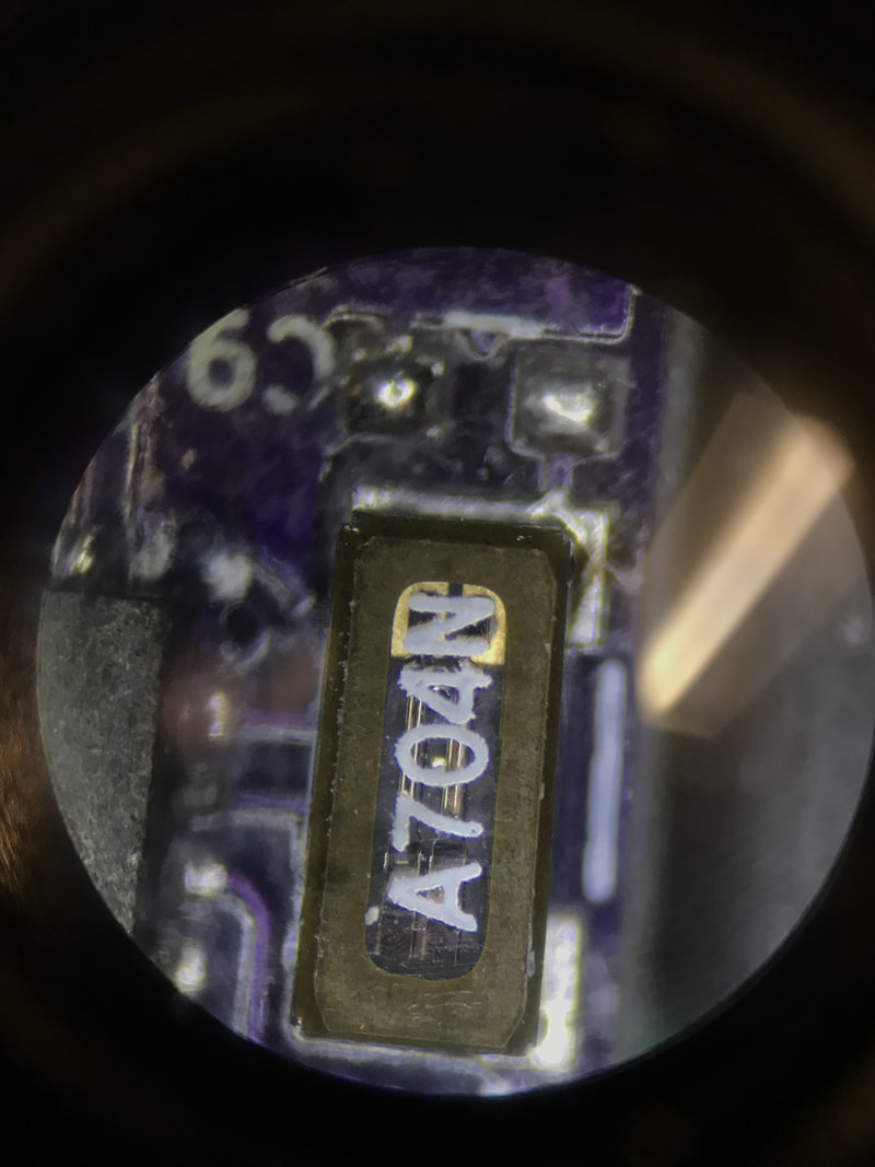 The new 9pF crystal. You can actually see the Tuning fork inside! |
Asynchronous Timing
The micro has this awesome ability to run Timer2 off of a different timing source than the rest of the chip. This means I can run Timer2 off of a 32.768Khz source for time keeping while running the rest of the chip at the 1Mhz or 8Mhz internal clock source of the chip. This makes me be able to not worry about all the timing irregularities I described in my last post having to do with such a slow clock. All you gotta do is change the fuses to use the internal 8Mhz clock (I did the divide by 8 as well) and then in the register ASSR = (1<<AS2). Once I get the oscillator working I might have to look deeped into the ASSR register for the external exclk bit workings but I'll post about it later. For now, I got a time keeping in a micro that can run its program reasonably fast and go back to sleep.
Look at these sources for reference on this matter:
AVR Timer2 asynchronous mode
AVR Freaks Forum Post
How to use a Quartz Clock
ADC changes
With the system clock running at 1Mhz I can now run the ADC module at the prescribed 50-200khz speed by changing the prescaler to be 8 so I get 125Khz. This allows me to read more channels in less time so no more flickering of the display. Sadly because the battery sense line is going through a voltage divider (look at schematic for reference) I can't source enough current to fill the sample and hold cap of the ADC. The 1Megaohm is just too much capacitance for a fast sample rate of 125Khz to be able to see it accuratly. So I added a 4.7uF cap to ground from that Vbatsense line and now it works just great.
With the system clock running at 1Mhz I can now run the ADC module at the prescribed 50-200khz speed by changing the prescaler to be 8 so I get 125Khz. This allows me to read more channels in less time so no more flickering of the display. Sadly because the battery sense line is going through a voltage divider (look at schematic for reference) I can't source enough current to fill the sample and hold cap of the ADC. The 1Megaohm is just too much capacitance for a fast sample rate of 125Khz to be able to see it accuratly. So I added a 4.7uF cap to ground from that Vbatsense line and now it works just great.
PRR and Power Draw
The microcontroller has a ton of useful sleep modes to reduce power while you're not doing anything. As far as I know only an interrupt can wake you up from sleep. So I've set up my project to wake up every 250ms, check the accel and if the angles aren't correct then go back to sleep. The following piece of code allows for super low power draw:
The microcontroller has a ton of useful sleep modes to reduce power while you're not doing anything. As far as I know only an interrupt can wake you up from sleep. So I've set up my project to wake up every 250ms, check the accel and if the angles aren't correct then go back to sleep. The following piece of code allows for super low power draw:
//set sleep mode register
SMCR = (1<<SM2) | (1<<SM1) | (1<<SM0); //set sleep mode as extended standby
sleep_enable();
//disable digital inputs connected to ADC input pins
//since ADC channels 2, 3, 4, and 5 are used we build 0b0011110=0d30
DIDR0 = 30;
//set PRR register to turn off all unused peripherals
//7=TWI, 6=TC2, 5=TC0, 3=TC1, 2=SPI, 1=USART, 0=ADC
//Since we only need TC2 and SPI to always work, and ADC is set but ADC init we have this:
PRR = 186; // 0d186 = 0b10111010;
I also did some measurements to see how much I'm pulling from the battery at each config, here's the result. You can see the system clock really plays a big roll in the awake current which then affects the average current but the faster the clock the quicker it gets its job done and goes to sleep so there might be a local minimum I'm skipping over depending on your application.
System Clock |
Average Current |
Wake Current |
8Mhz |
146 uA |
3800 uA |
1Mhz |
80 uA |
870 uA |
128Khz |
48 uA |
290 uA |
32Khz |
42 uA |
180 uA |
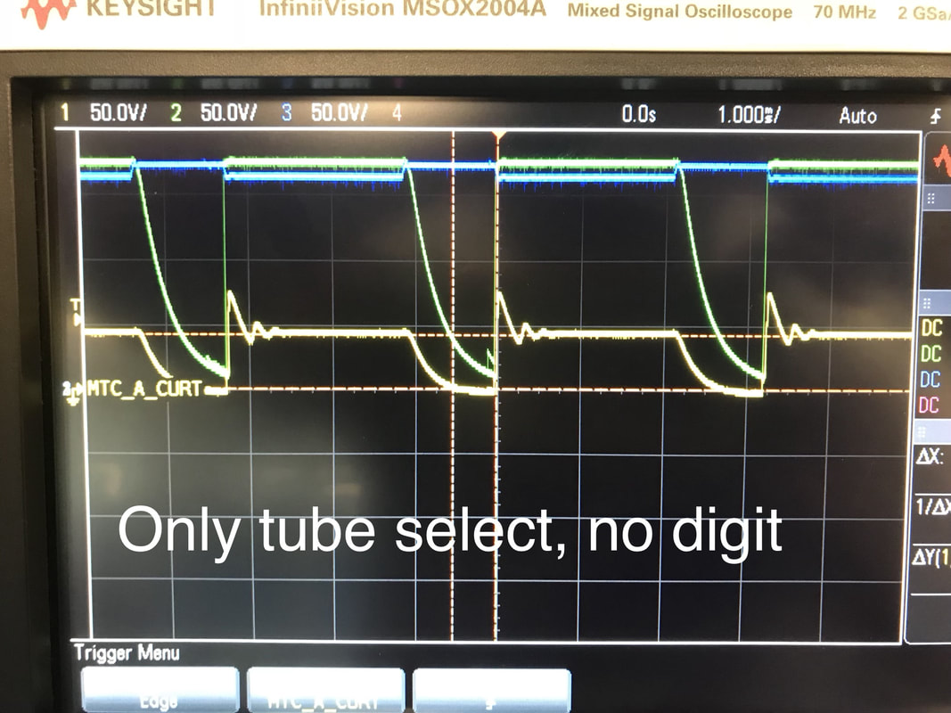
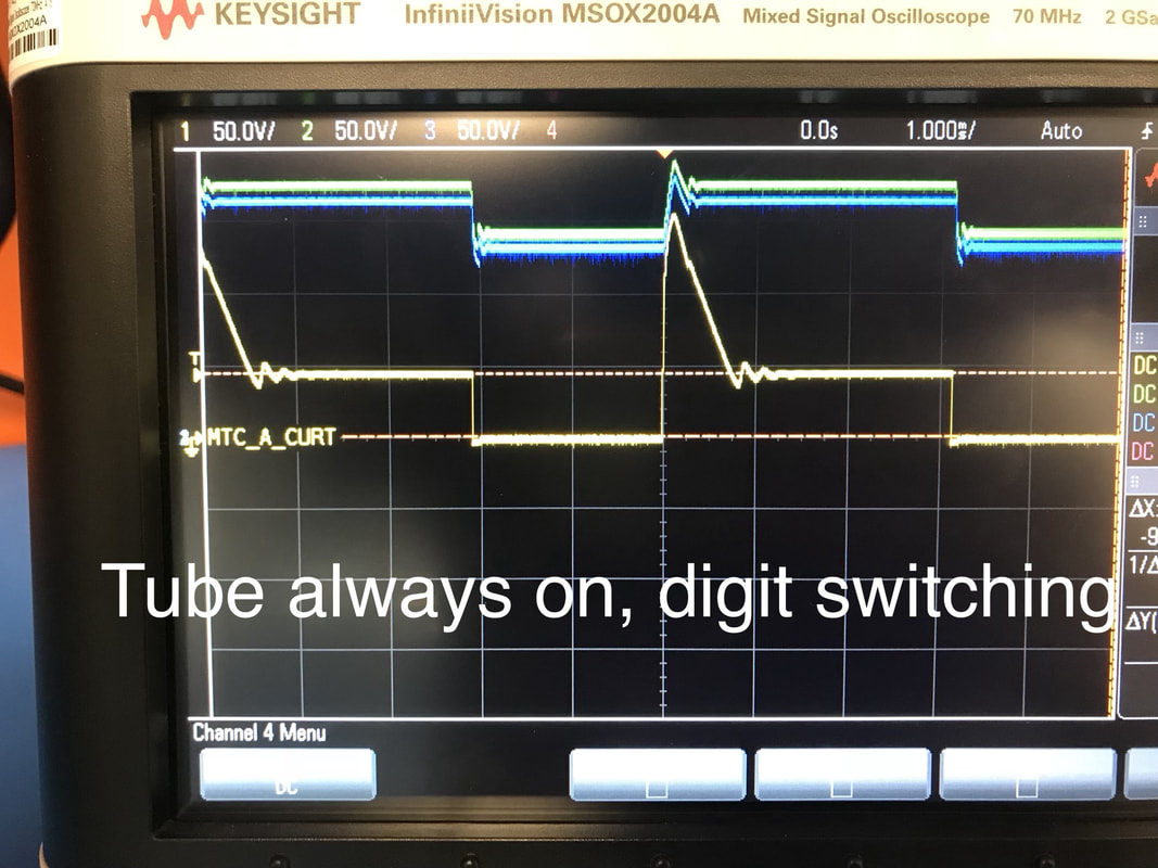
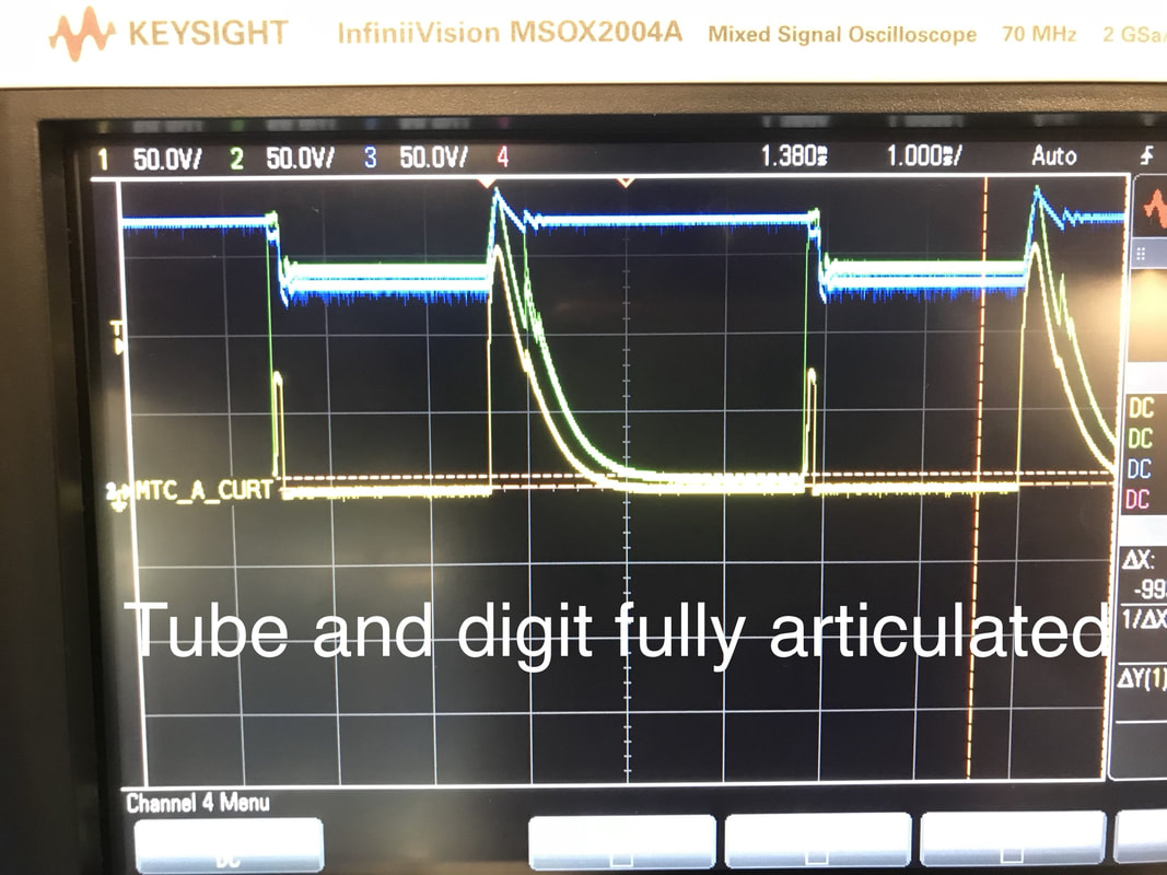
I draw about 100mA during firing displays if each digit is on for 2 milliseconds which is very decently bright. If we figure 30 firings a day with 3 seconds of display each we have the following:
24hrs / 30 firings = 2880 seconds / firing
(3s x 100mA) + (2877s x 80uA) = 530mAs
530mAs x (1h / 3600s) = 0.147mAh
0.147mAh x 30 firings / day = 4.41mAh / day
120mAh / 4.41mA = 27 days
Not too bad. So you'll have to charge the battery every month or so. We can even decrease that 100mA down to about 70 or 80mA if we go to a dimmer 1ms fire time towards the end of battery. Glad to see we're in the ball park.
Accelerometer
I was getting scared the accel was broken since the z direction wasn't working. Asked a technician friend to reflow the part. Ended up cutting the Vdd and Enable pins of the accel so I can always supply it with power but just use the micro to command it on and off. It'll take about 1 uA during disabled mode but It cuts down on the length of time needed for the outputs to settle at the correct voltage. I used to have to wait like 100ms now I'm down to 10ms. Still a lot but it'll have to do. I can't leave it on all the time either since it draws like 250uA or something crazy.
I was getting scared the accel was broken since the z direction wasn't working. Asked a technician friend to reflow the part. Ended up cutting the Vdd and Enable pins of the accel so I can always supply it with power but just use the micro to command it on and off. It'll take about 1 uA during disabled mode but It cuts down on the length of time needed for the outputs to settle at the correct voltage. I used to have to wait like 100ms now I'm down to 10ms. Still a lot but it'll have to do. I can't leave it on all the time either since it draws like 250uA or something crazy.
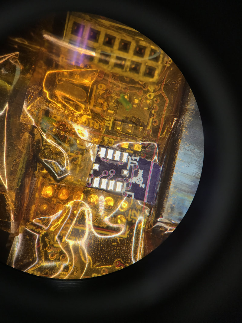 ADC reflowed off and trace cut | 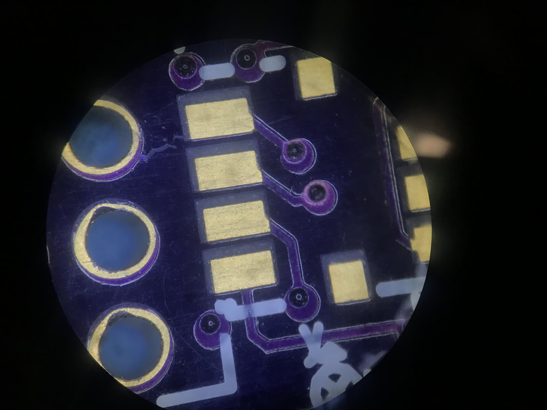 Pretty bad register between pad and solkmask from OshPark on this |
Bulk Capacitance
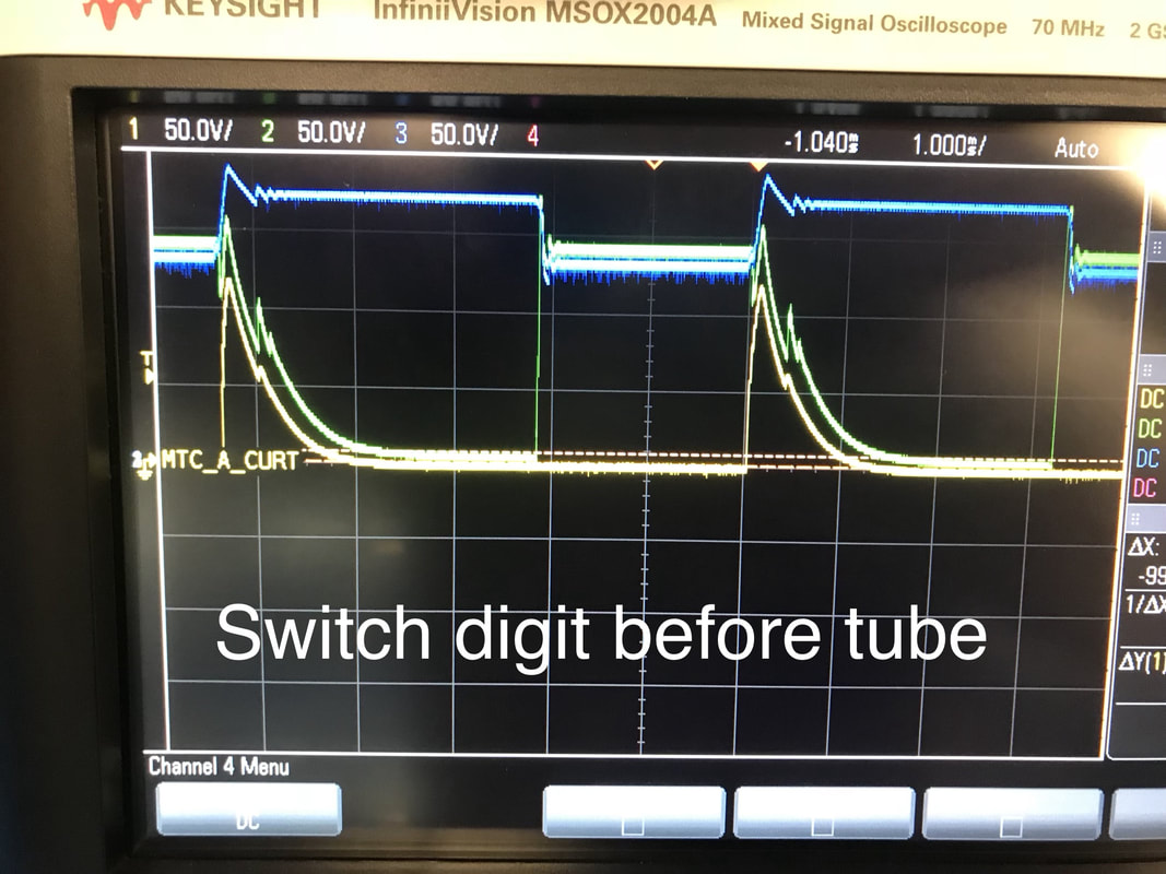
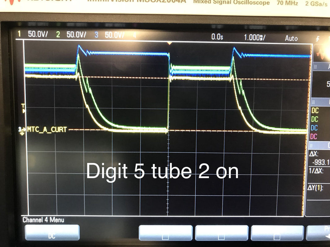
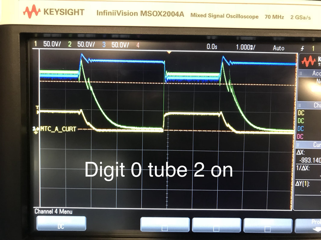
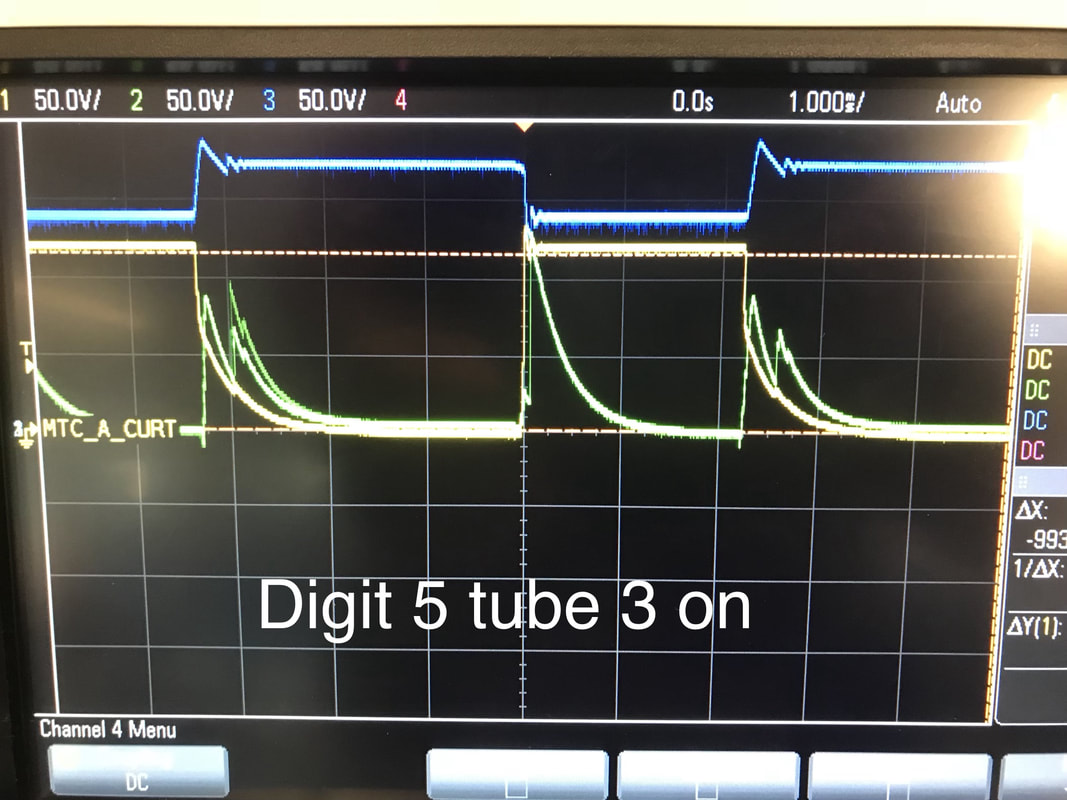
Took a gander at what the boost converter is doing to the vbatt line as it draws current and damn is it crazy. In some cases it's drooping the Vbatt line by a full volt! that's not good for the battery or the rest of the IC's. I put a temporary Aluminum Electrolytic 220uF cap on the line and it smoothed it out a bit. I suspect this cap has too much ESR to be effective, I'll look for a tantalum to replace it.
Took a gander at what the boost converter is doing to the vbatt line as it draws current and damn is it crazy. In some cases it's drooping the Vbatt line by a full volt! that's not good for the battery or the rest of the IC's. I put a temporary Aluminum Electrolytic 220uF cap on the line and it smoothed it out a bit. I suspect this cap has too much ESR to be effective, I'll look for a tantalum to replace it.
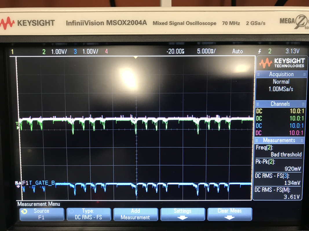 No Bulk Cap and the Vbatt+ and Vbatt- are shown drooping wrt to Gnd | 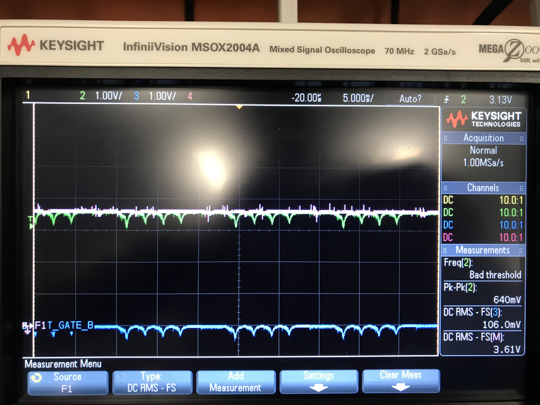 Added 220uF Electrolytic, not ideal but better |