Integrate PCB's
One of the biggest things I hadn't tested was the power board's ability to actually power a nixie because it's one thing to produce 180v with no load but another to deliver 2mA. So where the logic board would solder onto the power board I installed the same female headers I got in a couple other places so I can plug and unplug the dang thing as I debug. I now have a fully integrated unit with battery and all. When you plug the battery in, the protection circuitry trips, I think it's normal, you just short the Batt- and Gnd pins momentarily and its fine. I tried charging it as well and it works like a charm. So damn beautiful. The tubes start out fine but after a minute or so the power cuts out. It's as if the protection circuit slowly realizes it needs to cut the discharge because I can see the Batt- and Gnd voltages diverge. Not sure what's happening there but if I leave the tubes off it doesn't seem to trip. My current hunch is noise on the Batt+ and Gnd lines due to the boost converter, we'll see. Next stop is some software!
One of the biggest things I hadn't tested was the power board's ability to actually power a nixie because it's one thing to produce 180v with no load but another to deliver 2mA. So where the logic board would solder onto the power board I installed the same female headers I got in a couple other places so I can plug and unplug the dang thing as I debug. I now have a fully integrated unit with battery and all. When you plug the battery in, the protection circuitry trips, I think it's normal, you just short the Batt- and Gnd pins momentarily and its fine. I tried charging it as well and it works like a charm. So damn beautiful. The tubes start out fine but after a minute or so the power cuts out. It's as if the protection circuit slowly realizes it needs to cut the discharge because I can see the Batt- and Gnd voltages diverge. Not sure what's happening there but if I leave the tubes off it doesn't seem to trip. My current hunch is noise on the Batt+ and Gnd lines due to the boost converter, we'll see. Next stop is some software!
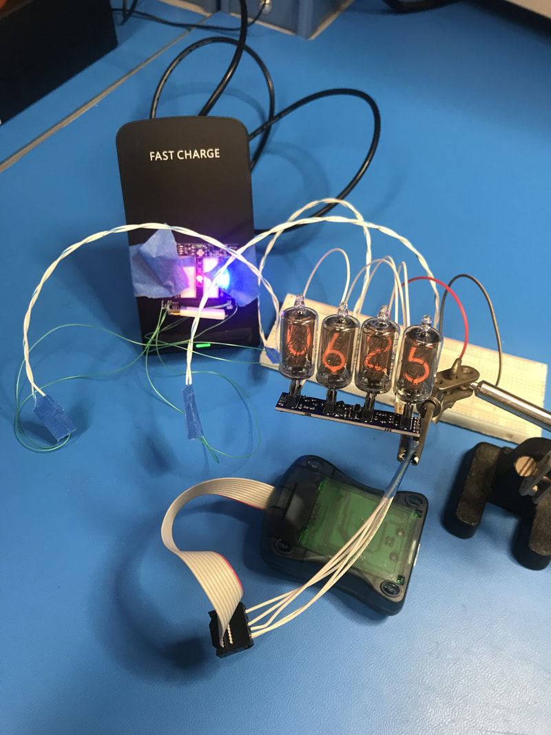 Plug boards in through a bread board first to make sure no surprises. | 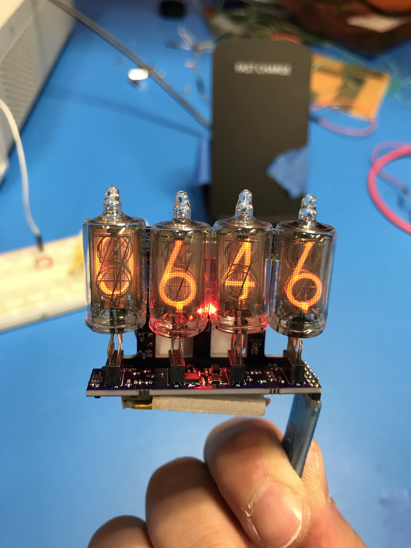 All connected! You got the battery at the bottom connected too. | 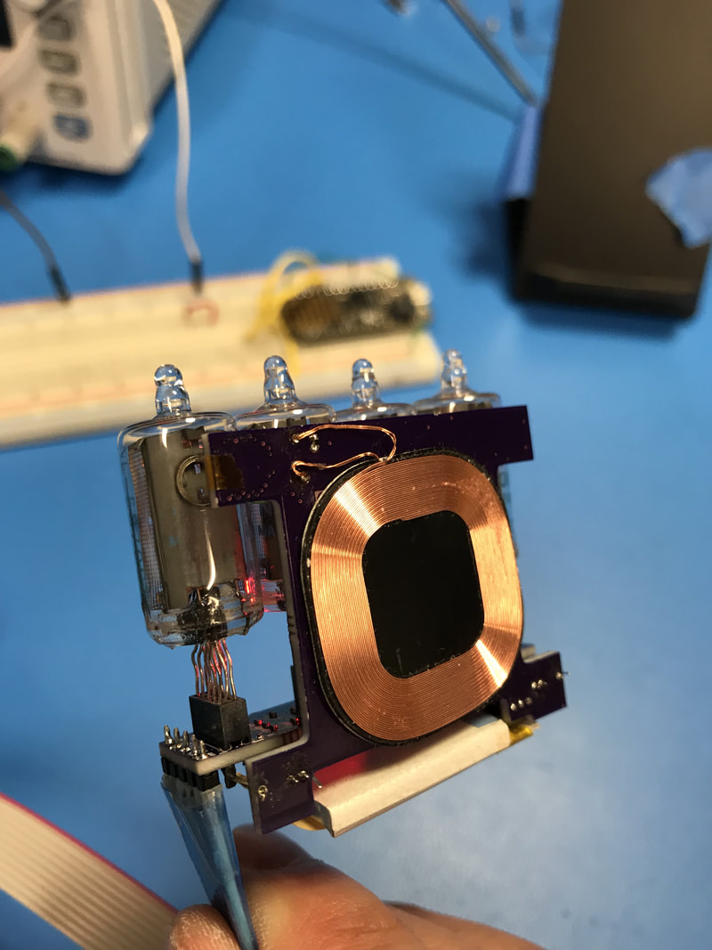 Back side, shows the coil and the recesses in the pcb where the tubes would sit. |
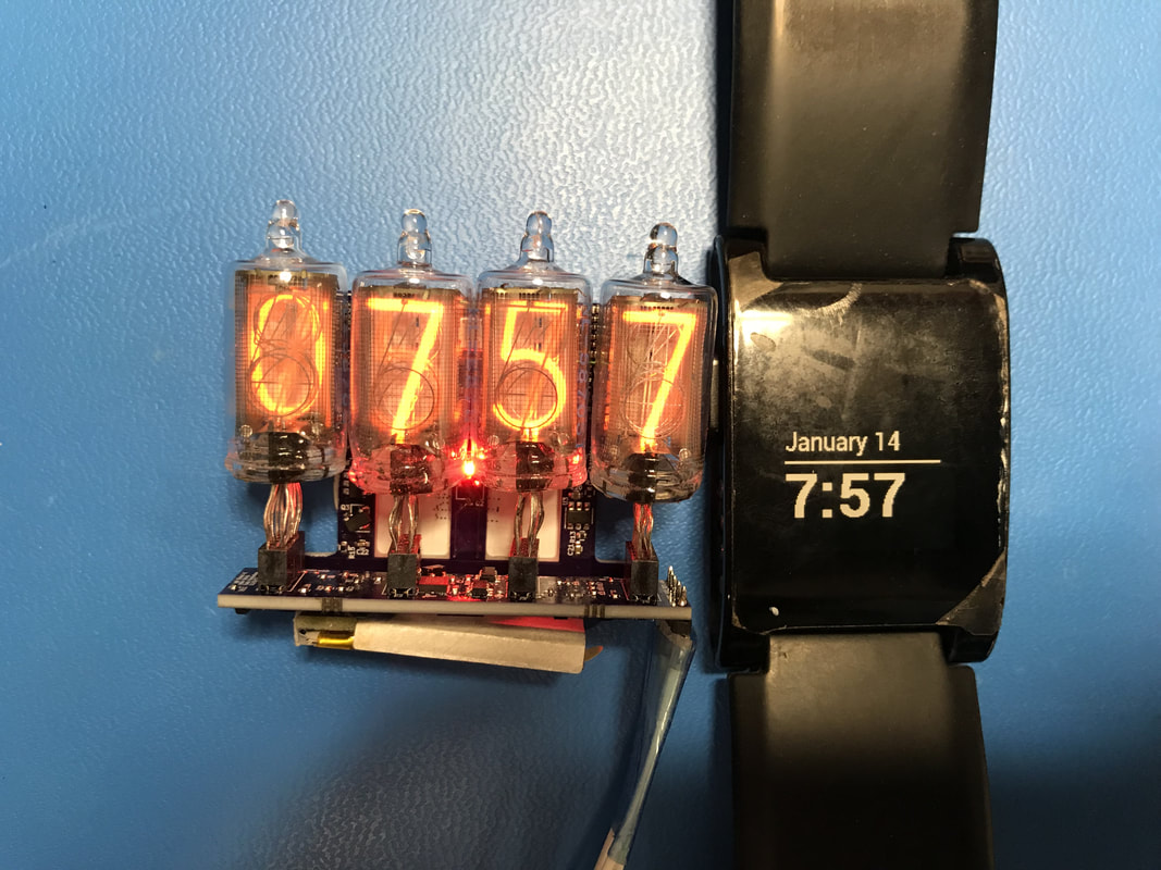 A shot with the pebble showing rough scale. Unfortunately the programming cable is soldered in for now so it's not fully on its own |  It charges like a boss! |
32.768 KHz is Slow
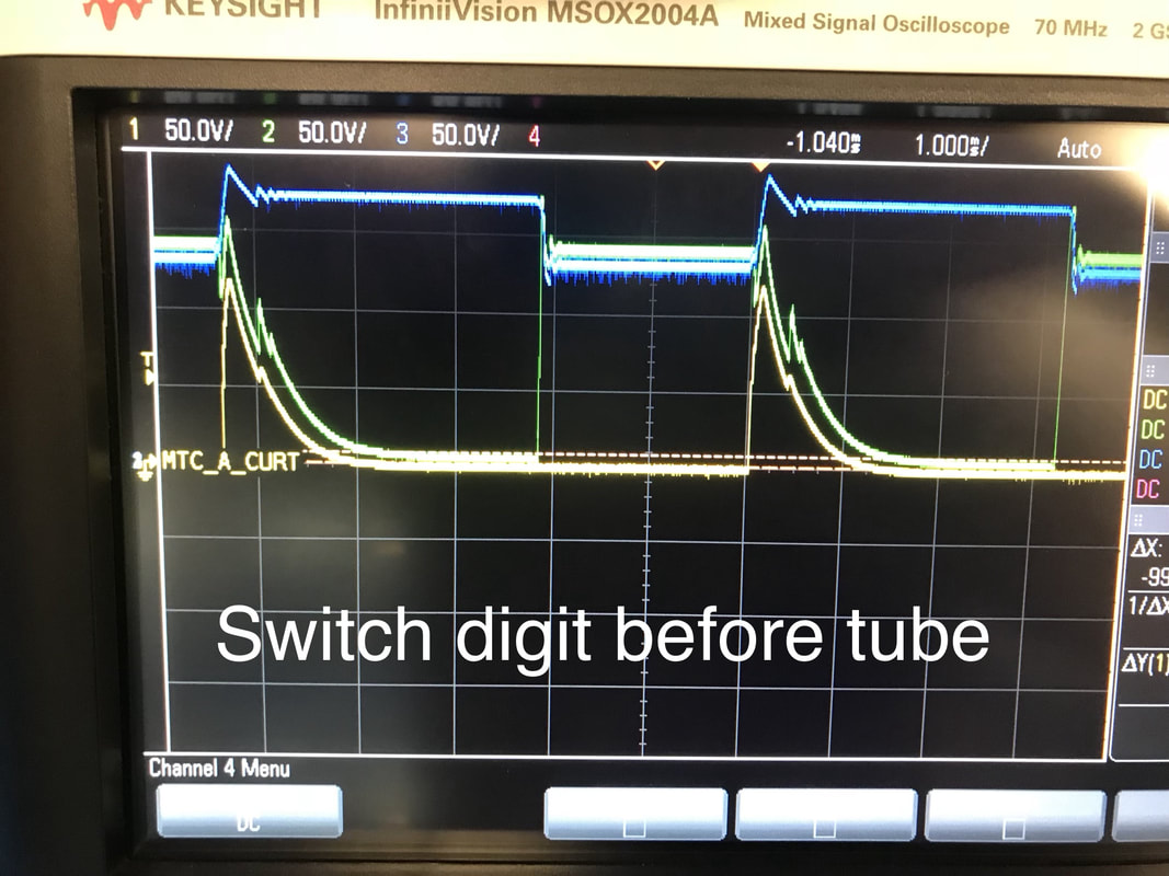
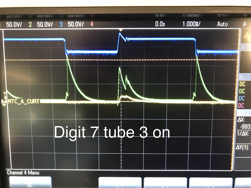
I'm no code monkey but man am I learning a lot on this topic fast. So the AVR's clock being this slow is presenting some hurdles. I was getting weird flickering sometimes on the tubes and I didn't understand why, so I hooked up wires to nets 1) Cathode7, 2) Anode2, and 3) Q6's gate to see how its working. So below is what i found. Keep in mind Yellow trace is Cathode7, Green trace is Anode2 and blue trace is Q6's gate. Check the schematics in the design package for reference.
I'm no code monkey but man am I learning a lot on this topic fast. So the AVR's clock being this slow is presenting some hurdles. I was getting weird flickering sometimes on the tubes and I didn't understand why, so I hooked up wires to nets 1) Cathode7, 2) Anode2, and 3) Q6's gate to see how its working. So below is what i found. Keep in mind Yellow trace is Cathode7, Green trace is Anode2 and blue trace is Q6's gate. Check the schematics in the design package for reference.
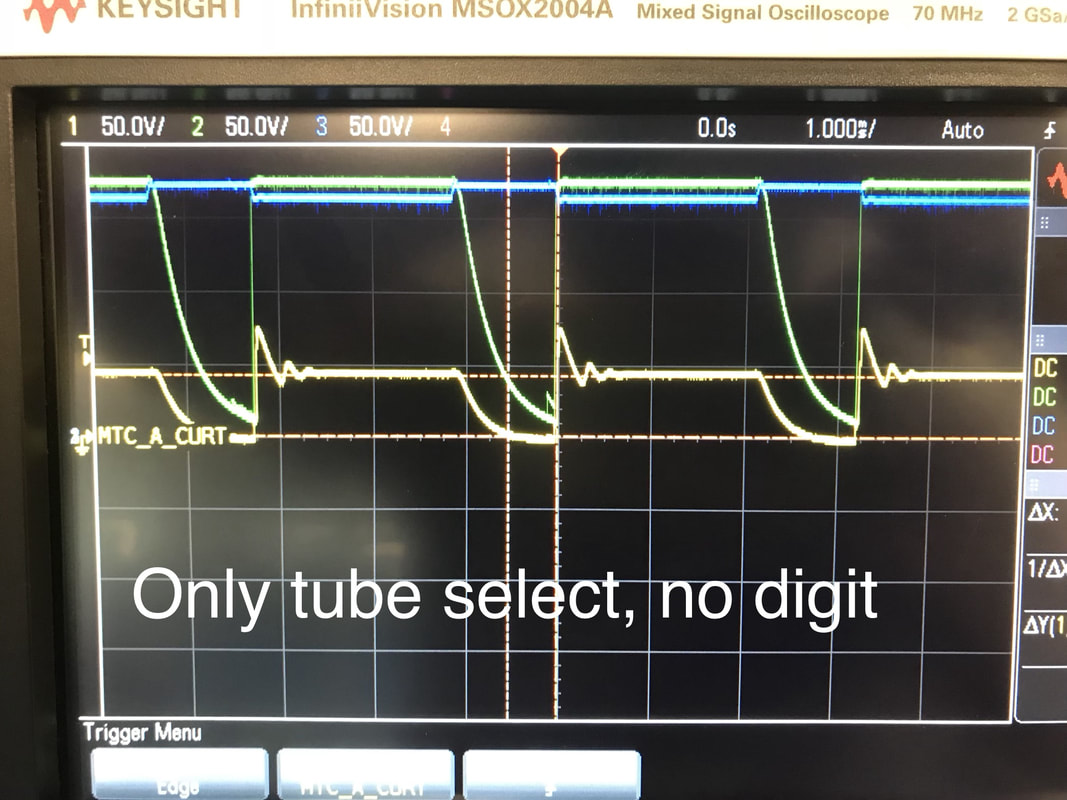 | First I ran code that selected no digit and only switched the second tube on and off. 2ms on, 1ms off. You can see the tube's cathode hangs at 50v which is kinda weird even if the anode is at 140v. |
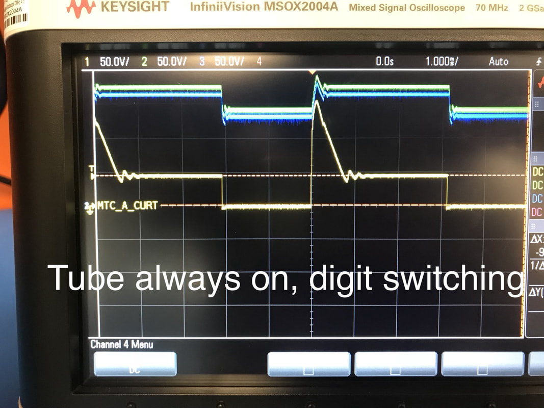 | Now we keep the tube on and switch the digit 7 on and off. 2ms on, 3ms off. You can see when the yellow trace is at 0v the tube is on, as it turns off, the cathode goes way high before settling at 50v again. |
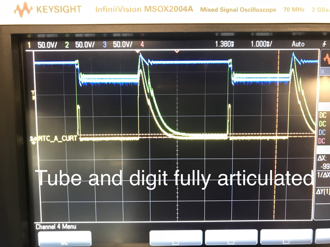 | Now we're switching both tube 2 and digit 7, 2ms on, 3ms off. So it's weird that during off times both anode and cathode sit at 0v. The little yellow blip before a turn on time is the delay between the CPU turning on the tube anode before it turns on the cathode (SLOWWW) |
 | Now I'm doing the same thing as above but my routines for driving the tubes first chooses the cathode then the anode so the blip is gone. The time it takes read, left shift, XOR, and write a value to a register is what we're seeing with the blip. It's crazy slow! |
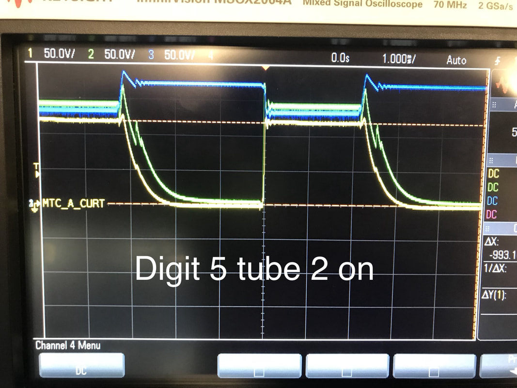 | Now I start switching digit 5 on instead. You can see the anode for digit 7 goes all the way to 100v! So the cathode doesn't always just chill at 50v |
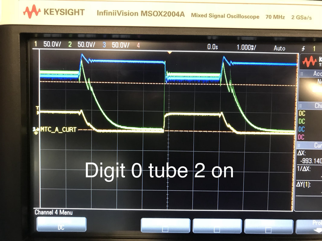 | No I switch digit 0 and cathode 7 is back to 50v! so the pin for cathode 5 is adjacent to the pin for cathode 7 and the pin for cathode 0 is super far from the pin of cathode 7 and I think they are stacked like that too in the tube. So when "5" is lit it induces a higher voltage in the "7" numeral than when "0" is lit because its further away. Not sure, just a hunch. |
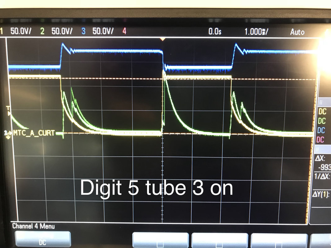 | Now I turn off tube 2 and switch tube 3 with digit 5, super interesting as the cathode 7 goes super high due to tube 3's numeral 5 being lit but since tube 2 is off its anode drops back to ground within a millisecond. It's doing funky things on each transient which is probably due to the construction of the nixie tube, these arn't just nichrome wires in here lighting up. Notice that during this case tube 2's number 7 is reverse biased. |
 | Now we light tube 3's digit 7 and as expected the cathode gets driven to ground while the anode eventually goes to 0v but experiences some transients like before. |
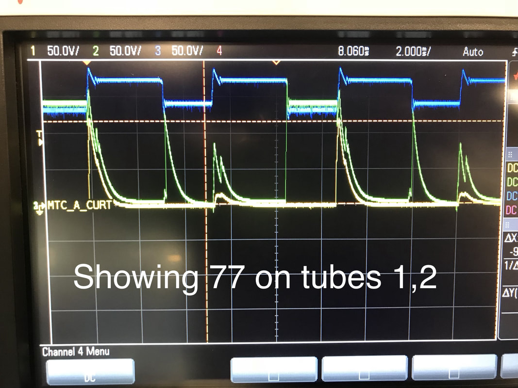 | So no I'm displaying both 7 on both tubes 1 and 2, going back and forth between them. You can see everything we learned in the past hand full of test cases all together which is pretty neat. |
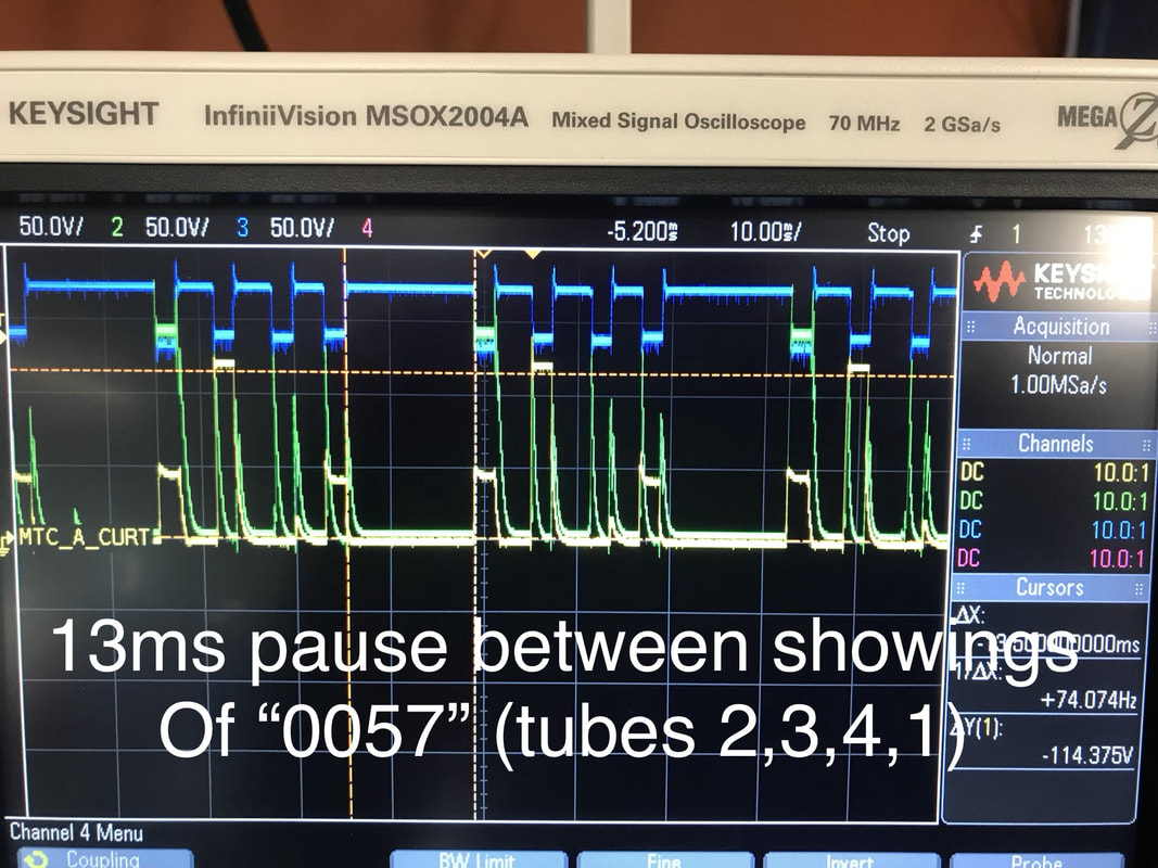 | This last picture leads me to the software being slow again. I was showing the numbers 0057 on tubes 2,3,4, and 1 respectively in that order. The program calculates how to show the integer 57 by chopping it up to 0 thousands, 0 hundreds, 5 tens, and 7 ones. I had a modulus operator in the calculation for some reason and the AVR was breaking its neck taking 13ms to do the calculations! I took out the modulus and 13 turned into 3. |
Other things I learned:
- When I have a toggle pin with a delay function in my main.c it keeps timing just fine. When I bury the function a couple functions deep the delay gets widened by 0.5 to 1ms. This is most likely due to the AVR having to go back to memory as it digs its way through the program stack. I urge you to read about the stack and heap memory stuff, I knew about it in principal but never saw it before my eyes in practice like this.
- The ADC take 13 clock cycles of the ADC clock which is half the system clock (so ~16khz). I had gotten into the habit of reading a few iterations of the same ADC port and picking the highest one since the AVR's datasheet says the ADC is rated for 50-200Khz. This is because the sample and hold capacitor voltage will dissipate naturally if the ADC isn't being clocked fast enough. My readings have been pretty accurate so it's not a huge problem but I was being safe. I may go to a clock double the speed I have now to mitigate the problem even though then the ADC still will only be at 32khz.
- Doing any read/write for registers is time consuming so if you know the value of the register just write it, no need to XOR and left shift your specific value.
- The ADC not being able to be read fast enough will bite me in the ass when I go turn my attention to gesture sensing but we'll cross that bridge when we get to it.
- The Crystal's 10ppm should turn to a 1 minute error over ~30 days but I'm seeing an error of 1 minute every 3 days which is horrible. I gotta look into outputting the timer interrupt's firing vs the oscillator on a pin so I can see whats out of order
- So the ATMEGA168pb has two 8 bit timers and one 16 bit timer. If I wanna use the sleep function for the AVR I'll have to use the 8 bit counter since that's the only thing that stays awake through a CPU sleep command but if I can push current draw during normal idle times down close to current draw during sleep I can trade battery life for time accuracy since I'll be able to calibrate each oscillator's tolerance through that 16 bit timer. We'll see, some work to be done here, starting with the previous bullet.
