Logic Board
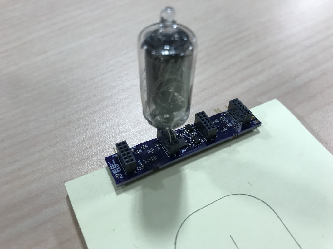
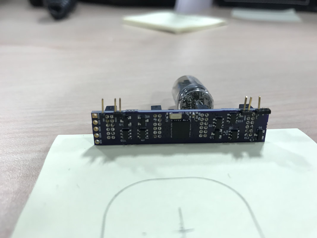
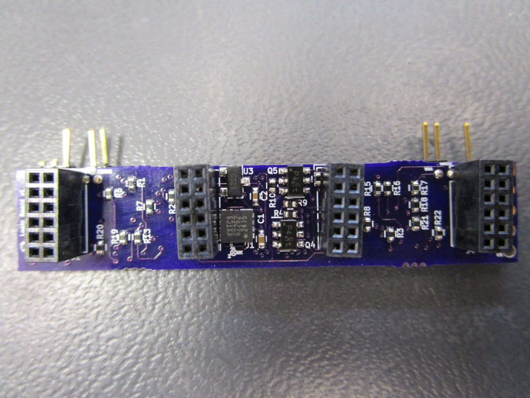
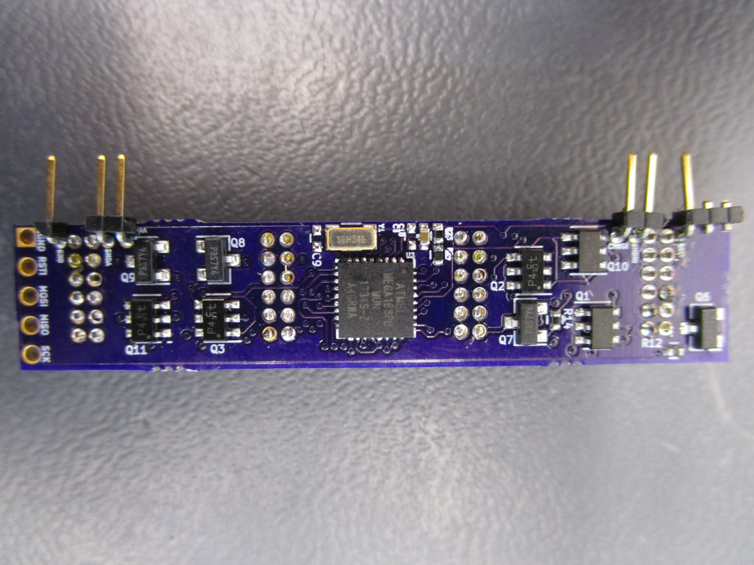
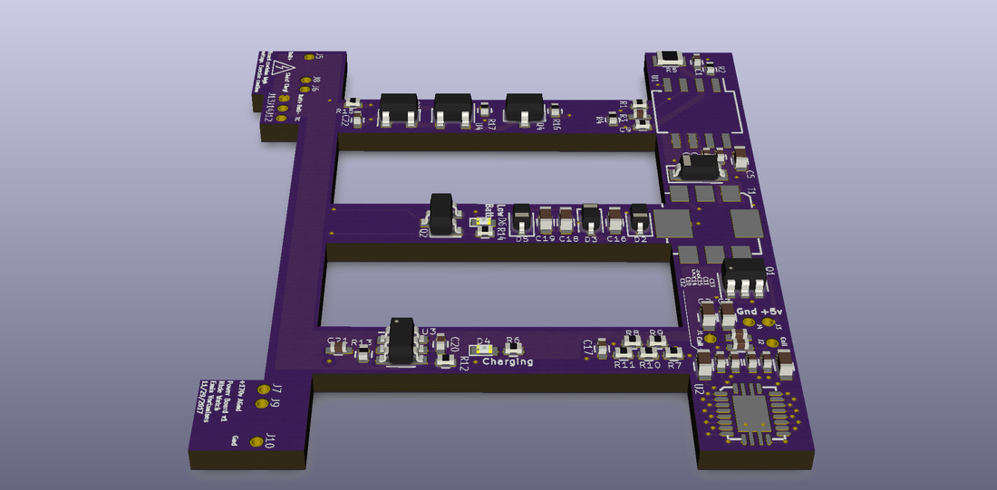
The Logic board arrived from Oshpark. I had ordered the parts from digikey and they came just in time as well so I assembled the board over a couple hours. Look at the design package attached below for schematics, BOM, and layout. I've alredy found one a few things wrong with the design like the 3v3 regulator pin assignment was incorrect and I let the magic smoke out. But otherwise I've successfully talked to it with my usbtiny ICSP from adafruit and atmel studios. I've also read a couple of the accelerometer outputs (for some reason Z is not working, maybe a reflow problem). I'll have to start hitting the code development a lot harder perhaps over the holiday break but initial efforts have been really fruitful. The High voltage is generated from the old perf board circuit I had made a month or two ago.
The Logic board arrived from Oshpark. I had ordered the parts from digikey and they came just in time as well so I assembled the board over a couple hours. Look at the design package attached below for schematics, BOM, and layout. I've alredy found one a few things wrong with the design like the 3v3 regulator pin assignment was incorrect and I let the magic smoke out. But otherwise I've successfully talked to it with my usbtiny ICSP from adafruit and atmel studios. I've also read a couple of the accelerometer outputs (for some reason Z is not working, maybe a reflow problem). I'll have to start hitting the code development a lot harder perhaps over the holiday break but initial efforts have been really fruitful. The High voltage is generated from the old perf board circuit I had made a month or two ago.
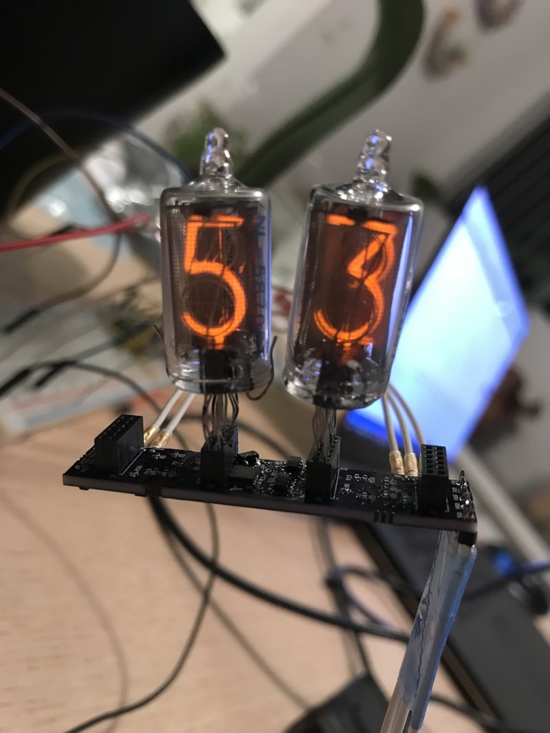 |  Displaying the angle as I move it back and forth by reading the accel and converting counts to angles. Flickering is due to camera shutter. |
 |  |  |  |
| LogicBoardDesignPackage.pdf |
Power and Battery Boards
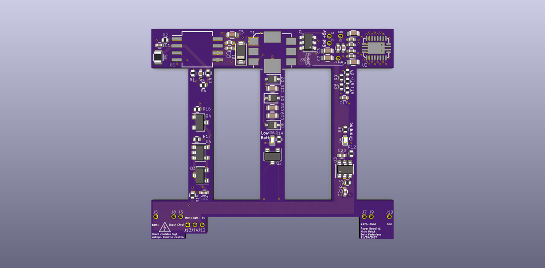
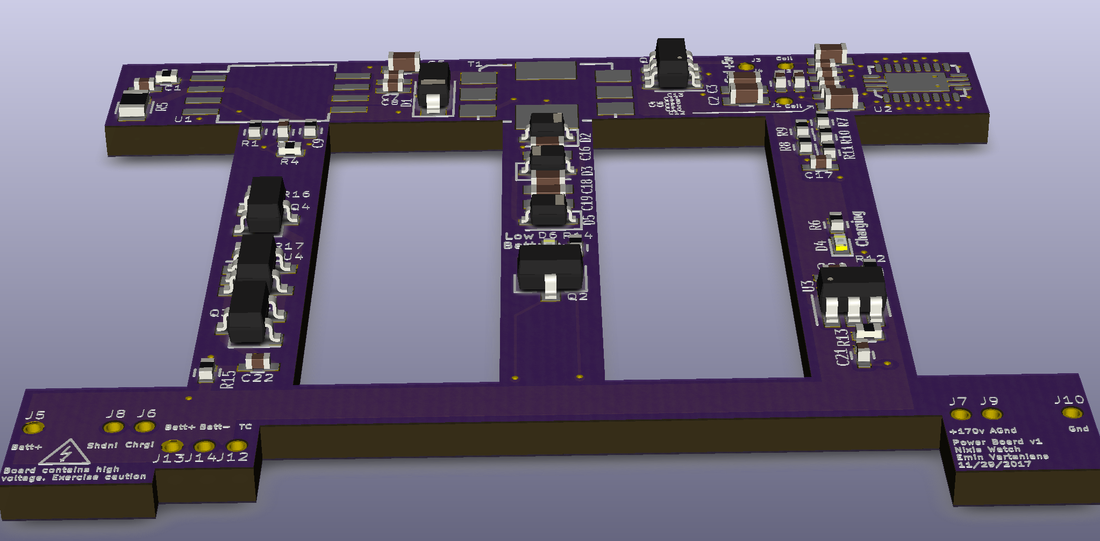
Finished designing the Power board a bit ago. A lot of thought went into making sure the battery doesn't blow up or I have proper protections for overdischarge and charge. The wireless charger is the biggest risk so we'll have to see how well it does when I get the board back and build it up. A big worry is aluminum in the case messing with the charging and actually heating up. Check out the picture and design package for the Power PCB.
Finished designing the Power board a bit ago. A lot of thought went into making sure the battery doesn't blow up or I have proper protections for overdischarge and charge. The wireless charger is the biggest risk so we'll have to see how well it does when I get the board back and build it up. A big worry is aluminum in the case messing with the charging and actually heating up. Check out the picture and design package for the Power PCB.
 |  |  |
| powerboard_design_package.pdf |
Battery
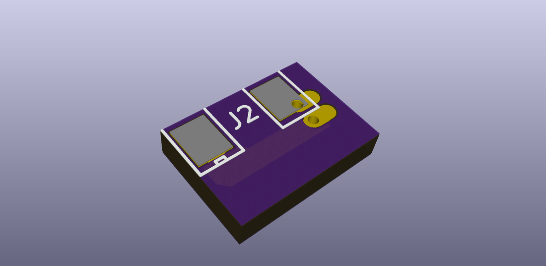
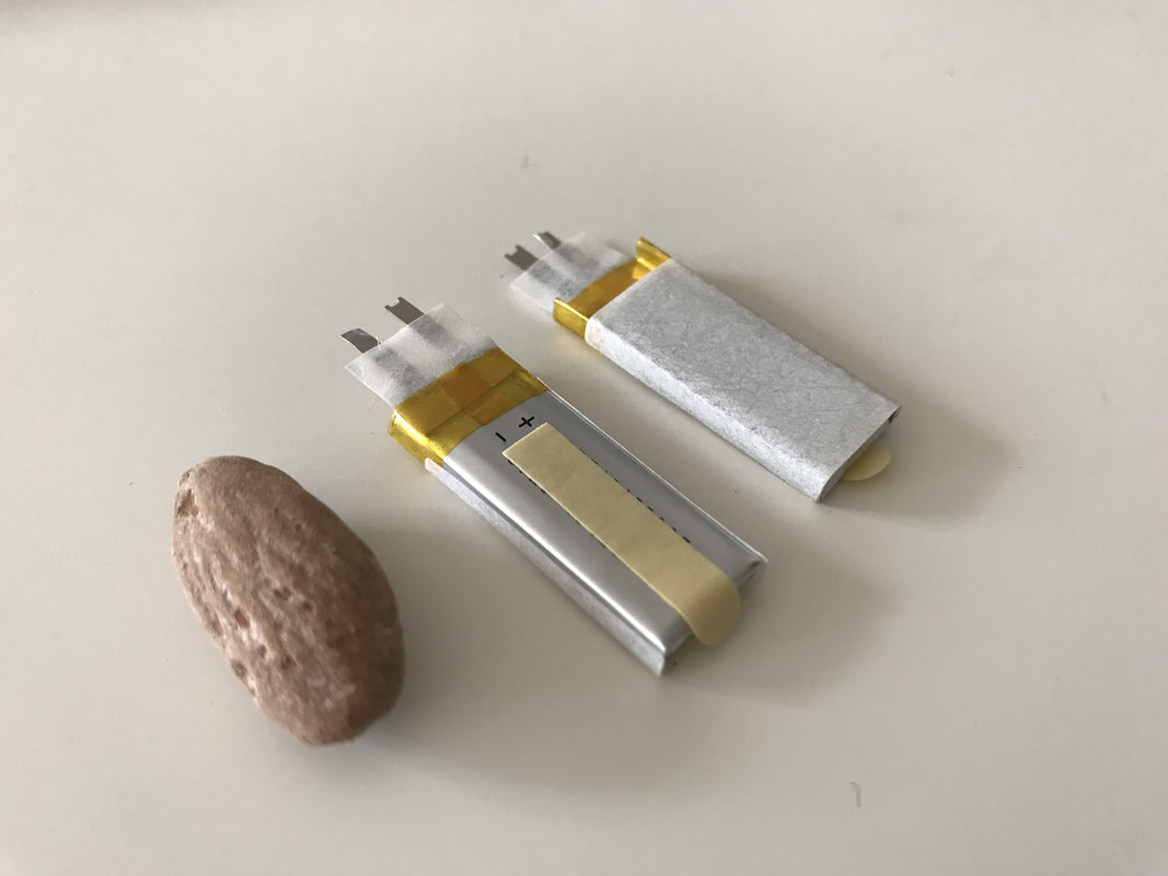
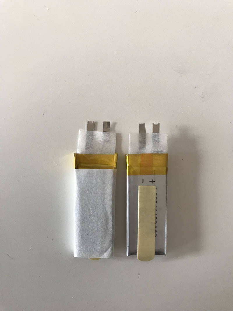
The battery is pretty tiny but only has tabs so I made a super tiny pcb that solders onto the tabs and provides headers for interfacing with the power board. I'll have to trim the battery tabs to shape for the board but we'll see...
The battery is pretty tiny but only has tabs so I made a super tiny pcb that solders onto the tabs and provides headers for interfacing with the power board. I'll have to trim the battery tabs to shape for the board but we'll see...
   |  |
| batteryboard_layout.pdf |
Next Steps
I'll be waiting for the power and battery PCB's from Oshpark. I've got parts already here. One of the biggest things is wireless charging with a cheap samsung charger. Also, continues code development on the log board. I gotta get my bearings straight with the interrupts and low power states just so I know what registers I'm working with. Then I'll delete everything and make a comprehensive state diagram of what the code would be doing so I can plan the development logically.
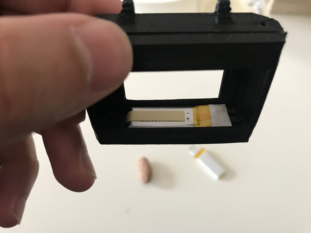
I was originally going to wind a coil myself for the receive side but that turned to be crazy. Then I made a PCB with a coil inside but to get the Q factor I needed with descent inductances I'd need like a 5 or 6 oz board which wasn't going to happen for cheap. Finally found some COTS coils made for this stuff. I I also researched to find most receive units just have a ferrite instead of a magnet so they can stick to the magnetic pad correctly without sticking to your keys or whatever. So all this has pushed some case changes which I'll have to work on as well.
I'll be waiting for the power and battery PCB's from Oshpark. I've got parts already here. One of the biggest things is wireless charging with a cheap samsung charger. Also, continues code development on the log board. I gotta get my bearings straight with the interrupts and low power states just so I know what registers I'm working with. Then I'll delete everything and make a comprehensive state diagram of what the code would be doing so I can plan the development logically.
I was originally going to wind a coil myself for the receive side but that turned to be crazy. Then I made a PCB with a coil inside but to get the Q factor I needed with descent inductances I'd need like a 5 or 6 oz board which wasn't going to happen for cheap. Finally found some COTS coils made for this stuff. I I also researched to find most receive units just have a ferrite instead of a magnet so they can stick to the magnetic pad correctly without sticking to your keys or whatever. So all this has pushed some case changes which I'll have to work on as well.
